
3D structure parameterization design and modeling for irregular structure of stope bottom①
2016-12-06 02:39ZengQingtian曾庆田WangLiguan
High Technology Letters 2016年1期
Zeng Qingtian (曾庆田), Wang Liguan
(*School of Resources and Safety Engineering, Central South University, Changsha 410083, P.R.China)(**Yuxi Mining Co., Ltd., Yuxi 653100, P.R.China)
3D structure parameterization design and modeling for irregular structure of stope bottom①
Zeng Qingtian (曾庆田)②***, Wang Liguan*
(*School of Resources and Safety Engineering, Central South University, Changsha 410083, P.R.China)(**Yuxi Mining Co., Ltd., Yuxi 653100, P.R.China)
Stope mining design is a very important and complicated task in daily production design and technical management of an underground mine. Based on workface technology and human-computer interaction technology, this study introduces a method of 3D parametric design for the irregular structure of stope bottoms, and focuses on solving technical problems in surface modeling of stope bottom structure. Optimization of the minimum span length algorithm (MSLA) and the shortest path search algorithm (SPSA) is conducted to solve the problem of contour-line based instant modeling of stope bottom structures, which makes possible the 3D parametric design for irregular structure of stope bottom. Implementation process and relevant methods of the proposed algorithms are also presented. Feasibility and reliability of the proposed modeling method are testified in a case study. In practice, the proposed 3D parameterization design method for irregular structure stope bottom proves to be very helpful to precise 3D parametric design. This method is capable of contributing to improved efficiency and precision of stope design, and is worthy of promotion.
irregular stope bottom structure, stope, structure parameterization design, surface reconstruction, modeling
0 Introduction
3D design is a new method of design based on a digital, virtual and intelligent platform. This method abandons the idea of planar and 2D design, and is capable of vivid 3D presentation of the designing target. 3D design has been well practiced in such fields as machinery, automobile, aircraft, shipbuilding, electronics, light industry, construction, chemicals, textiles and apparel, and is playing an important role in these said fields. While in the mining industry, this is not the case. The structure of a mine is usually presented in both natural and artificial forms. Existence of the very complex natural structure of a mine long precedes its artificial counterpart. 3D simulation of the natural structure of a mine includes deposit, geological construction and topographical properties, which can be fulfilled only through geological modeling. It is in the simulation of the artificial structure of a mine such as the developing system, the stope and the various chambers that 3D design becomes helpful. Geological modeling based 3D simulation for the natural structure is the basis of 3D design of mining. Therefore geological modeling and 3D modeling must go together in the mining industry. For this reason, 3D design practiced in the mining industry is unique from those in other industries.
Development design in the mining industry, namely the design of mining infrastructure, is commonly completed by qualified design institutes and normally lasts short time. Stope design, in contrast, is conducted throughout the whole mining activity, accounting for over 60% of technical workload. Therefore, it is very important to meet the need of efficiency and quality of stope design. In this study, a method of 3D parametric design for irregular structure of stope bottom is presented. This method is proposed based on the digital 3D mining software platform DIMINE. In this method, 3D CAD technique is applied in a manner that is parametric and human-computer interactive[1,2]. Application of this method in DIMINE helps solving the problem of parameterization for stope bottom and improves the efficiency and quality of mining stope design.
1 Study on the parameterization of 3D stope bottom structure
1.1 Process and requirements of mining stope design
A mining stope design consists of stope mining preparation design and blasting design. Mining preparation design, as presented in Fig.1, matters most as it directly affects the dilution rate, the difficulty of geostatic pressure control, mining safety and economic benefits. It ranks first in terms of workload throughout the whole mining activity.

Fig.1 Stope mining design process
Requirements of mining stope design include:(1)Rational selection of mining method;(2)Proper mining efficiency;(3)High recovery rate of ore;(4)Low dilution rate;(5)Good economic benefits;(6)Standard design with proper illustration of mining preparation design and a complete set of relevant figures and tables.
1.2 Parameterization of 3D stope bottom structure
Mining stope bottom with funnels consists of ore extraction units including scraper drift and ore extraction drift. Trenches and mining stope bottom without funnels also consist of their ore extraction units respectively. Therefore, parameterization of 3D mining stope is conducted upon various ore extraction units. Trenches and mining stope bottom without funnels are actually parts of the roadway engineering. Due to their simplicity in structure, no further study upon these said subjects is made. A thorough analysis upon the parameterization of mining stope bottom with funnels is made with Fig.2. Structure of stope bottom with funnels can be figured out with the four parameters: funnel interval, funnel displacement, horizontal roadway length and vertical roadway length of connecting funnel. For stope bottom with staggered pattern of funnel distribution, its structure can be figured out through entirely displacing the funnel from one side by half funnel interval.

Fig.2 Parameterization of mining stope bottom with funnels
2 Parametric design and modeling techniques of the irregular stope bottom structure
2.1 Workflow of mining stope parameterization design
Mining stope design consists of the selection of a proper mining method, blueprint design of mining stope, and the calculation of relevant economic and social indexes under the constraint of the deposit, the mining development system[3]and the technical mining condition. Precise 3D parametric design of mining stope is built on the basis of 3D mining development system model and digital deposit model. It is the design of mining preparation and cutting engineering in 3D space in line with certain mining method. In the said design, hybrid model of solid and block model is used for the calculation of relevant economic and technical indexes. To put it simply, 3D mining stope design is the design of mining preparation engineering with specific shape and size in 3D space.
(1)Precise location of space for mining stope design
To realize precise location of space for mining stope design, workface technology and human-computer interaction technology are used. For a specific mining stope to be designed, precise space location starts from the input of measured data. The workflow is presented in Fig.3. As it can be seen, the space location of the tunnel and the span of the mining stope to be designed are figured out first. In line with the mining method selected, the measured original point and the orientation of the tunnel, design of the along-vein workings is then made certain and that of roadway is done in accordance with the normal distribution principle.
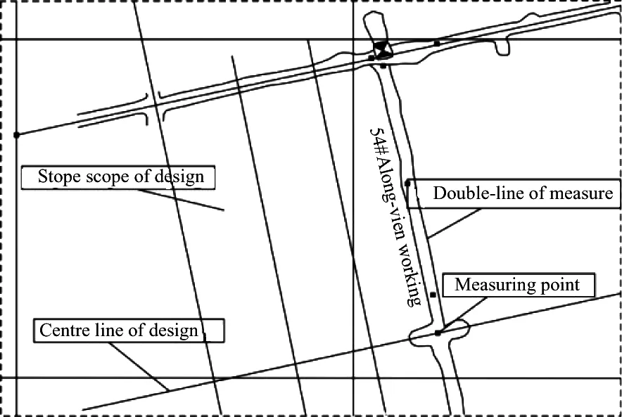
Fig.3 Location of space for mining stope design
(2)The key of the 3D parametric design for mining stope bottom structure lies in the design of stope bottom structure. The stope bottom structure comes with various tunnel section patterns. When designing the mining stope, protection for scraper or ore extraction drift should be considered. As a result, the funnel of mining stope bottom is irregular in most cases.
The main idea of precise 3D parametric design for stope bottom structure includes the following steps. Firstly, the location of the scraper drift and the first pair of funnels, scattered in symmetric or staggered pattern is figured out. Then the four variable parameters of funnel interval, the distance between the central line of the funnel and that of the scraper, horizontal roadway length and vertical roadway length of connecting funnel are input into the human-computer interactive interface to get the central line of the stope bottom where the whole scraper drift lies. The last step is setting each specific part of said central line with certain section patterns and size, and uses the centline and section method[4]and the surface regeneration algorithm for stope bottom structure to build solid model for mining stope structure. The whole process of this design is presented in Fig.4.

Fig.4 3D precise parametric design process of bottom structure
(3) Methods of precise design for other parts of the mining preparation engineering
The design of other parts of the mining preparation engineering is mainly done by adding the planar graphs and the cross-section drawings of relevant stope bottom structure. Said graphs and drawings are defined as different working faces. Central lines of parts of the mining preparation engineering will be formed in line with their spatial relation to each other. The centline and section method will be used to generate a solid model for these parts of the mining preparation engineering. The above mentioned process is presented in Fig.5.
2.2 Human-computer interaction and precise location for space design
The process of mining stope engineering design as presented in Fig.5 shows that precise 3D design of mining preparation depends on its precise 3D location. Mining preparation engineering can be divided into different categories by the way ore is transported. The conventional ore transportation by scraper consists of its bottom structure (the scraper, horizontal roadway and vertical roadway of connecting funnel, the funnel and the chamber), the connection shaft, the draw shaft, personnel and material transporting shaft, undercut slot, undercut shaft and tunnel; while by mechanization, it includes the transportation drift, the ore excavation drift, ore-drawing trench, undercut slot, undercut shaft and tunnel, and personnel and material transporting shaft[5-7]. To realize precise 3D parameterization design, it must figure out the two issues as precision and parameterization. Normally, the following technologies are used to serve this purpose.
(1)CAD workface technology of 3D mining
3D mining stope design by digital mining software is done on the basis of 3D CAD application in mining. Precise location of a certain point in 3D environment needs the building of auxiliary line and auxiliary face. Conventional CAD design is actually done on 2D drawing workface which is familiar to engineers from all walks of life. Therefore, the transformation of 3D space into a series of 2D working faces is needed in terms of the need of engineers’ working habit and precise 3D space location.
The transformation of 3D space into 2D working faces is done by inserting a certain 2D working face or sets of working faces defined and created by the designer. 3D CAD application in mining is exactly the technique needed in precise 3D design of mining preparation engineering in that it helps with 2D working face building in 3D environment. The designer first snaps points or lines in 3D space or draws points or lines in a visual space in 3D environment, and then projects these points or lines into the wanted 2D working faces. This practice allows the transformation of 3D space into a series of wanted 2D working faces. The way this transformation is done is presented in Fig.6.

Fig.6 Schematic diagram of 3D mining CAD workface precise design
(2) Human-computer interaction technology
Human-computer interaction technology is another key technology needed in precise 3D design of mining preparation engineering. Application of this technology helps with the parameterization issue. The essence of parametric design technology lies in the constraint put upon 3D model in terms of its location and size. In the proposed technology, variable and invariable parameters coexist. For 3D parametric design of mining stope, the former consists of the size and location of mining stope engineering, while the latter is normally the section shape of regular mining stope engineering. Adjustment of the size of mining preparation engineering can be made by adjusting the said variable parameters. 3D parametric design function in digital mining software is in essence a user interface through which the user can practice relevant operations including dynamic input or selection of coordinates of points, the setting of parameters of relevant location, selection of objects, and adjustment of variable parameters[8]. This interface bridges a gap between human and computer. Through this interface, parameter-driven graphic system is made possible, which helps delivering satisfactory designing result.
2.3 Key algorithm of modeling for bottom structure with irregular funnel
In mining preparation engineering design, modeling of those parts with regular section can be quickly done by centline and the section method, while that is not the case for mining stope bottom structure. It is due to the consideration of protection for important engineering like the scraper drift. Existence of the engineering makes the funnel irregular, which in turn leads to irregular mining stope bottom structure as shown in Fig.7. Modeling of irregular mining stope bottom structure lies in the regeneration of surface bound by various contour lines[9,10]. Concerning the surface regeneration, excellent algorithms abounds[11,12]. In this study, the minimum span length algorithm (MSLA) and the shortest path search algorithm (SPSA) are applied[13]. On their basis, an improved algorithm for surface regeneration is put forward, which helps optimizing the correspondence relation between points in different contour lines, leading to instant modeling of irregular mining stope bottom structure and improved triangular network of the solid model. An introduction of the proposed algorithm for surface regeneration is the following.

(a) Funnel with irregular height and opening;(b) Funnel with irregular opening
(1) Building correspondence among points in different contour lines
The basic idea of building correspondence among points in two contour lines is to try to connect all the points in two adjacent contour lines in one shot. For certain part of a contour line, a weight is set upon it. This weight means the length proportion of this part in the whole contour line. Take Fig.8 as an example, the following can be obtained:

Fig.8 Correspondence among points
(2) Building mapping function
When the source and the target matching C is established, the mapping function is built, which is the most important procedure in this algorithm. The function describing the matching of source U and target C(U) is defined as
W(U,t)=tU+(1-t)C(U), t∈[0,1]
(1)
Using the similar function structure, the mapping function for the profile outlines could be built. As shown in Fig.9, assuming profile outline C is the source and profile outline D is the target, after the matching is established, the following definition is obtained:
CC: C→D
Then for any pair of ci∈C, CC(ci)∈D is a matching point, if L transitional profile outlines P={pk, 1≤k≤K} are to be established, for any P1, similarity factor α∈[0,1] is introduced denoting their approximate rate to the sources, and it is assumed that the approximate rate is decreasing one after another for all the L transition profile outlines, which means the value of α is related to 1. Thus the following is obtained:
α=1/L
According to Eq.(1), the following equation is obtained:
P1=αC+(1-α)CC(D)
(2)
It is known from Eq.(2) that, it approximates to C at a bigger value while approximates to D at a smaller value.
It is known from Eq.(2) that, using the same method, L transitional profile outlines needed can be established. For the profile outlines including line C and D, using the algorithm described by Eq.(1), a fast reconstruction of the surface formed by the profile outlines can be realized.
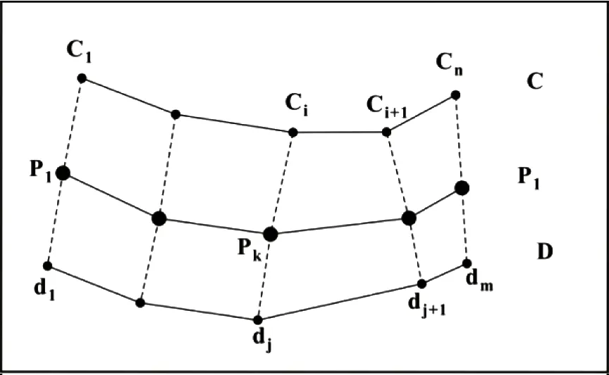
Fig.9 Transition contour calculation
2.4 Design and modeling for mining preparation engineering and mining stope
The most commonly used method for modeling of mining stope bottom structure with irregular funnel is the contour line based solid surface regeneration. In this method, certain algorithms are used to realize the automatic connection of points in contour lines, which contributes to triangular patches. The solid model of mining stope bottom structure can be formulated by consolidating those patches. Surface regeneration by contour line helps figure out the optimal triangular patch based optimal approximation method of object surface. Surface regeneration is done under the constraint of spatial geometric properties of the solid object. Despite of irregular height and mouth shape of funnels of different bottom structures, they resemble each other in terms of geometric properties. As surface generation involves not modeling of complex structure including holes and branches, the improved MSLA algorithm is capable of optimizing the correspondence relation between points in different contour lines. The mapping function resulted from this algorithm contributes to network of triangular patches with finer granularity. As a result, instant modeling of bottom structure with smoother surfaces presenting better regularities is made possible.
The proposed algorithm proves to be highly reliable. For contours with similar shape and size that are parallel to each other, modeling of mining stope bottom structure by this method is capable of yielding satisfactory model. It should be noted that modeling by this algorithm does not demand the number of points in different contour lines exactly the same. The implementation process of the proposed method is shown in Fig.10.
2.5 Calculation of technical and economic indexes of hybrid model of stope solid model and octree block model
In this study the solid model generated by the above mentioned surface regeneration algorithm is used to constrain the geological statistics based octtree block model for ore grade evaluation[14,15]. The proposed algorithm is capable of automatic ally calculating statistically and analysiy different variants in digital mining software system. Based on existing digital mining software systems, the following method is designed for the calculation of technical and economic indexes of models built with the surface regeneration algorithm.
2.6 Development of digital mining software
The proposed DIMINE mining software is developed based on HOOPS platform with the help of Microsoft Visual C++ language. It is a 3D design and modeling software containing functions of geology, mining, surveying and production planning. Presently, the software has been widely used in underground and open-pit mines in China and is of important practical value in the field of 3D mine modeling and 3D design. 3D structure parameterization design and modeling technology for irregular structure of stope bottom studied in this paper has been applied to DIMINE software and a module of underground mining design has been added to the software to settle the problem of 3D structure parameterization design and improve the efficiency and quality of stope design.
3 Case study
A certain mining enterprise in Yunnan province has been using 3D digital mining software in geological modeling and 3D design of mining since 2002. The past decade witnessed the building of a complete 3D mining digital model system. This model system includes a geological database, terrain models, fault models, ore body models, block models for ore grade evaluation, and the mining development model. An overview of this model system is given in Fig.11.

Fig.11 3D digital deposit model
The mine owned by this mining enterprise is a typical gently inclined mine with medium thickness, which poses difficulty for mining. The mining method with arch pillar,sill pillar and inter-chamber pillar is used in mining this mine. Distribution of planned chamber and pillar is shown in Fig.12.
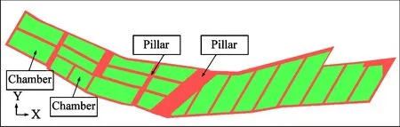
Fig.12 Planned chamber and pillar
575-46II-I2is the code of the mining stope to be designed. This code signifies that the stope is located in the 46th prospecting line at 575m level. The mining object is the iron-copper polymetallic orebody scattered in the I2seam. Draw shafts are set to transport ore in the double track drift in the 575m level. Three scraper drifts are laid along the strike with funnels placed at both sides of the scraper feeding ore.
A total of 27 pairs of funnels are set. The interval between two adjacent funnels is 6.5m, and that for two adjacent scraper drifts is 12.7m. The bottom structure is 7m high. The width of sill pillar is 4m, and so is that of arch pillar. Both eastern and western pilasters are in width. Three sublevels are designed for mining.
The average height of a sublevel is 12.5m. In the northeastern part of the chamber a cutting slot is set. According to these data, the 3D parametric design method for irregular stope bottom structure as mentioned above is used to help with the design of this specific mining stope bottom. The model established by this method is presented in Fig.13.

(a) Stope mining project layout (b) Overall stope mining model
Once the stope mining design is completed, hybrid model of block and grade model should be built[15]. The calculated technological and economical indexes are given in Table 1. Fig.14 presents the automatic drawing result of mining preparation engineering implementation by 3D digital mining software in line with the conventional drawing standard.
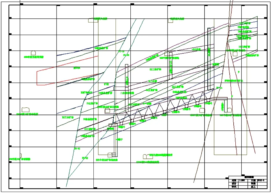
Fig.14 Autographed stope design profile
It can be seen from Table 1 that the application of 3D design has contributed to satisfactory dilution and loss rate. Therefore, good economic returns can be well expected.
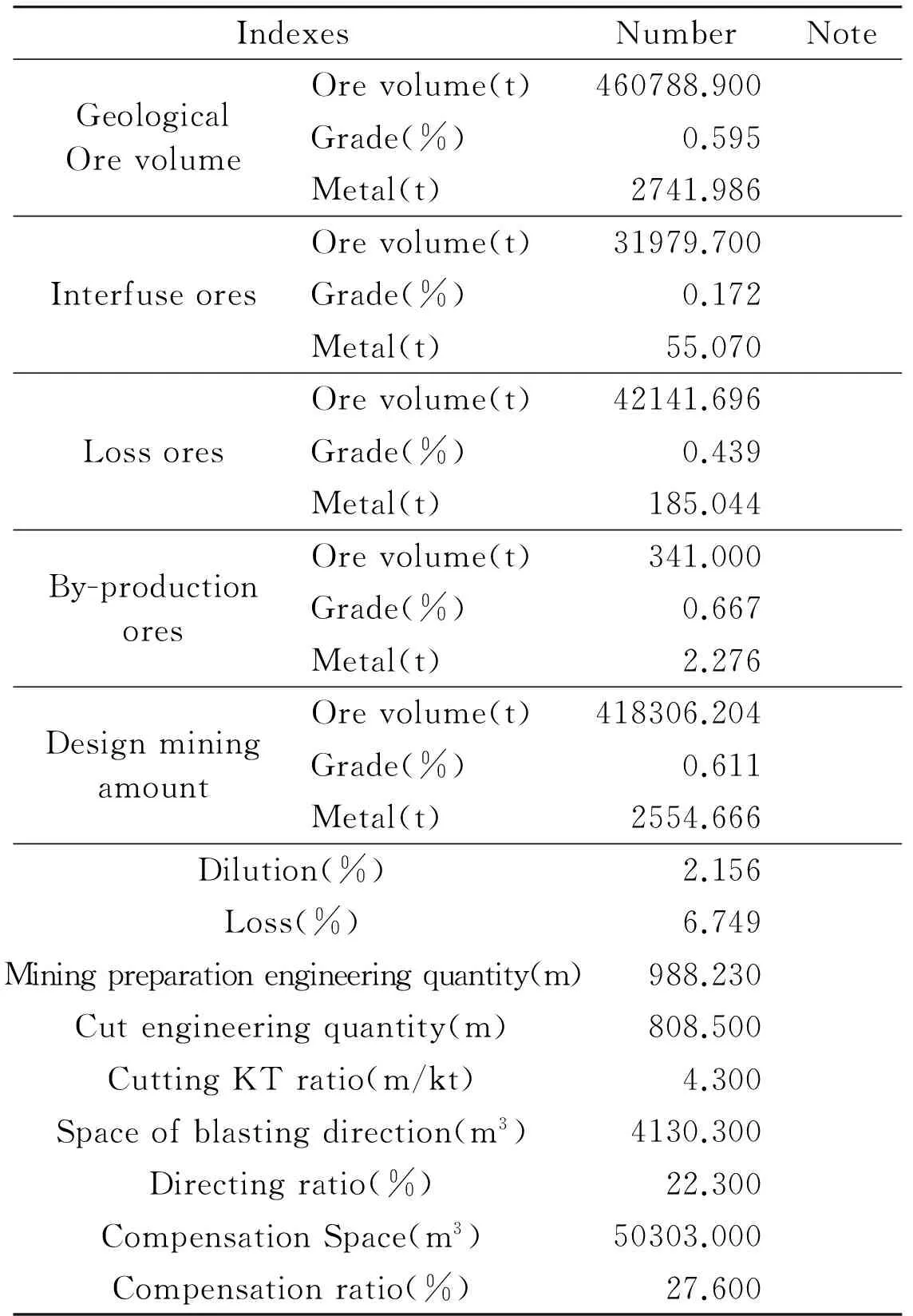
Table 1 Mining design techno-economic indexes
4 Conclusions
In this study, a thorough study concerning 3D parametric design and modeling of irregular stope bottom structure is made. A key algorithm about stope bottom structure modeling is presented. It is proven that the proposed method is applicable to 3D parametric design and modeling of irregular stope bottom structure. Due to its high efficiency and precision, this method is now well used in many large mining enterprises with good results yielded.
(1) Contour line-based 3D modeling of irregular mining stope bottom structure with funnels. This modeling method is of high reliability and is applicable to different mines. It is a useful method for mining preparation engineering design.
(2)Parametric design method for irregular mining stope bottom structure with funnels. This 3D digital mining software based design method witnesses the combination of workface technology and the human-computer interaction technology. It can very well settle the problem of mining preparation engineering design, and it is thus worthy of promotion.
(3)Unlike the machinery industry, the mining industry is characteristic of irregular structures like tunnels and stope bottoms. Structures like which cannot be bounded in 3D CAD platform. Therefore, to realize ideal 3D mining design, corresponding software must be developed.
[ 1] Lin B. Study of key technology of platform of digital mining software system: [Ph.D dissertation].Changsha: School of Resources and Safety Engineering, Central South University,2010. 27-29
[ 2] Dai C L. Research of parametric design theory:[Ph.D dissertation]. Nanjing: College of Aerospace Engineering, Nanjing University of Aeronautics & Astronautics,2002. 3-8
[ 3] Zhao X D. Tunnel Engineering. Beijing:China Metallurgical Industry Press,2010. 27-32
[ 4] Gu D S,Li X B. Modern Minging Science and Technology for Metal Mineral Resources. Beijing :China Metallurgical Industry Press, 2006. 710-711
[ 5] Xie S J. Metal Deposit Mining under Ground. Beijing :China Metallurgical Industry Press,1986. 19-24
[ 6] Department of Mining Design Manual Edit. Mining Design Manual(Deposit Exploitation Volume). Beijing:China Architecture and Building Press, 1987. 1-3
[ 7] Yang D. Metal Deposit Mining under Ground.Changsha:Central South University of Technology Press,1999. 146-158
[ 8] Sheiderrnan B. Direct manipulation a step beyond programming languages.IEEEComputer, 1983, 16(8):
[ 9] Sloan S W. A fast algorithm for constructing delaunay triangulation in the plane.AdvancedEngineeringSoftware, 1987, 9(1): 34-55
[10] Montani C, Scateni R, Scopigno R. Decreasing Iso2surface complexity via discrete fitting.ComputerAidedGeometricDesign, 2000:17
[11] Keppel E. Approximating complex surface interpolation technique for reconstruction 3D objects from serial cross2sections.ComputerVisionGraphics&ImageProcessing,1989, 48(1):124-143
[12] Fuchs H, Keddem Z M, Uselton S P. Optimal surface reconstruction from planar contours.CommunicationoftheACM, 1977,20(10):693-702
[13] Tan Z H. Study on key technology of mining design and production planning based on 3D visualization system:[Ph.D dissertation]. Changsha: School of Resources and Safety Engineering, Central South University,2010. 54-57
[14] Journel A, Huijbregts C. Mining Geostatistics. London: Academic Press, 1978. 7-18
[15] Jing Y B. Study and application on 3D hybrid geological modeling and attribute interpolation of mineral deposit:[Ph.D dissertation]. Changsha: School of Resources and Safety Engineering, Central South University, 2010. 42-45
Zeng Qingtian, born in 1980. He is presently staying at CSU to study mine digital technology etc. for his Ph.D degree in Mining Engineering. He received the M.S. degree in Safety Technology and Engineering from Central South University(CSU) in 2007. His research interests include digital mine technology and new mining technologies.
10.3772/j.issn.1006-6748.2016.01.008
① Supported by the National High Technology Research and Development Programme of China (No. 2011AA060407) and Yunnan Province Science and Technology Innovation Platform Construction Plans, China (No. 2010DH005).
② To whom correspondence should be addressed. E-mail: qingtian_zeng@163.comReceived on Feb. 5, 2015
 High Technology Letters2016年1期
- High Technology Letters的其它文章
- Mixing matrix estimation of underdetermined blind source separation based on the linear aggregation characteristic of observation signals①
- An improved potential field method for mobile robot navigation①
- Robust SLAM using square-root cubature Kalman filter and Huber’s GM-estimator①
- Time difference based measurement of ultrasonic cavitations in wastewater treatment①
- Research on the adaptive hybrid search tree anti-collision algorithm in RFID system①
- Selective transmission and channel estimation in massive MIMO systems①