
叶片进口安放角对泵作透平外特性影响的数值模拟与验证
2017-09-15 06:17孔繁余刘莹莹魏启能
农业工程学报 2017年15期
王 桃,孔繁余,刘莹莹,魏启能
叶片进口安放角对泵作透平外特性影响的数值模拟与验证
王 桃1,2,孔繁余1※,刘莹莹1,魏启能3
(1. 江苏大学流体机械工程技术研究中心,镇江 212013; 2. 西华大学能源与动力工程学院流体及动力机械教育部重点实验室,成都610039;3. 成都瀚能精密机械有限责任公司,成都 610039)
为充分探究离心泵作透平专用叶轮叶片进口安放角的确定方法,该文建立了液力透平专用叶轮叶片进口安放角与设计流量的关系表达式;基于ANSYS BladeGen与NX软件,分别设计了4个不同叶片进口安放角的透平专用叶轮;在试验验证基础上,通过全流场数值计算,分析了叶片进口安放角对透平外性能的影响。结果表明:叶片进口安放角从60°增大到72°、90°和105°时,透平高效点对应的流量分别为85、90、100和110 m3/h,4台透平数值计算最高效率点流量与理论计算设计流量基本吻合,表明采用该文推导的设计流量与进口安放角的关系式合理。外特性性能曲线显示随叶片进口安放角增大,透平高效点向大流量偏移,最高效率值有所下降,且下降的速率增大。综合考虑透平最高效率及高效区范围,对于比转速为193蜗壳式单级单吸离心泵反转作透平,叶片进口安放角宜设计在60°与90°之间。该研究可为液力透平专用叶轮设计提供参考。
泵;叶轮;模型;离心泵作透平;叶片进口安放角;设计流量;前弯叶片;性能预测
王 桃,孔繁余,刘莹莹,魏启能. 叶片进口安放角对泵作透平外特性影响的数值模拟与验证[J]. 农业工程学报,2017,33(15):98-104. doi:10.11975/j.issn.1002-6819.2017.15.012 http://www.tcsae.org
Wang Tao, Kong Fanyu, Liu Yingying, Wei Qineng. Numerical simulation and validation of effects of blade inlet angle on performance of pump-as-turbine[J]. Transactions of the Chinese Society of Agricultural Engineering (Transactions of the CSAE), 2017, 33(15): 98-104. (in Chinese with English abstract) doi:10.11975/j.issn.1002-6819.2017.15.012 http://www.tcsae.org
0 引 言
随着日益增加的能源需求与环境保护的要求,水电作为可再生的清洁能源在全球范围内得以广泛推广和应用。在微型水力发电中,若采用传统的轴流式、混流式或冲击式水轮机发电,由于较高的初期投资和运行成本,经济上不可行。泵是一种可逆式旋转机械,单级单吸离心泵反转作透平因具有成本低,运行维护成本少,占地空间小等优势,在微型水电开发与工业流程余能回收中被许多学者广泛推荐[1-5]。
近年来,国内外的学者主要围绕泵作透平的选型、运行稳定性与性能提高等方面开展研究[6]。泵出厂时,制造商通常不提供泵在透平工况下的性能曲线,若直接选用原型泵反转作透平,首要解决的问题是如何选择合适的泵,使其在透平工况运行时能够满足用户要求。虽然国内外学者通过试验研究、理论推导与数值模拟的方法导出了适合一定比转速范围的透平性能预测表达式,但由于泵几何型式的多样和复杂性,预测精度还有待进一步提高[7-13]。泵作透平在实际运行中常产生振动和噪声,影响机组运行的稳定性,严重时会影响机组的正常开机[14-17]。直接采用离心泵反转作透平时,除运行稳定性有待提高之外,透平效率通常不高于泵的效率,且高效区范围较窄。为提高透平运行性能,Derakhshan等[18-19]采用神经网络、基于梯度的叶片型线优化算法,重新优化叶型,透平效率有所提高。Giosion等[20-22]通过在叶轮进口前添加导叶改善透平运行性能。Jain等[9,23-24]均提出对透平叶片进口边倒圆及前、后盖板外圆修圆,可使透平效率提高1%~4%。Doshi等[25]通过试验同样指出对叶轮修圆,可提高透平效率,但提高的幅度十分有限,最高效率仅能提升1至2.5个百分点,建议对叶片进口角进行重新设计以更明显的改善透平性能。可见,国内外研究者主要通过优化叶片形状,添加导叶及叶轮修圆的方式提高透平性能,鲜有学者提出重新设计液力透平专用叶轮以显著提高泵反转作透平的性能。
因泵反转时蜗壳由压水室变为引水室,由于空间尺寸限制通常不能同水轮机一样在蜗壳与叶轮之间布置可调导叶,液体从蜗壳流出后直接流入叶轮进口;又因原型泵叶轮设计时只考虑泵运行工况,原型泵叶片的出口安放角(透平工况的进口安放角)通常取值在推荐的22°~30°范围[26],叶片形式通常为后弯型,若直接采用原型泵叶轮做能量转换核心部件,效率较低的问题不能得到根本改善。为提高透平能量特性,课题组从透平运行工况,在不改变其他过流部件的前提下,设计了前弯叶片型式的透平专用叶轮,通过试验和数值分析发现可显著提高离心泵作透平的效率[27]。为深入研究液力透平专用叶轮的设计理论与方法,课题组前期对液力透平专用叶轮直径的确定方法[28]进行了研究。文献[29]设计了叶片进、出口安放角均相同但安放角变化规律不同的3种叶片,研究了从叶轮进口到叶轮出口叶片安放角变化规律对泵作透平性能的影响,得出了安放角按线性分布规律透平性能较好的结论。叶轮设计时,叶片进口安放角是重要参数之一。文献[29]中未讨论叶片进口安放角的确定方法,也未涉及进口安放角如何影响透平外特性的问题。为研究叶片进口安放角对液力透平性能的影响,杨孙圣等[30]针对5个不同进口安放角的叶轮进行了数值模拟,分析了进口安放角对透平外特性的影响,并给出了叶片进口安放角的取值建议。但文献[30]中研究对象为一低比转速原型泵叶轮,叶片形式为后弯型,且研究内容并未涉及如何从理论方法上,依据不同的设计条件,确定合理的叶片进口安放角;其研究对象与研究核心内容与本文均不同。因此,有必要对液力透平专用叶轮叶片进口安放角与设计流量的关系及其对液力透平性能的影响展开深入研究。
本文以比转速为193带螺旋形蜗壳的单级单吸离心泵为原型,导出了叶片安放角与设计流量的关系表达式,设计了4个不同叶片进口安放角的透平专用叶轮,分析了叶片进口安放角对透平外性能和水力损失分布的影响,验证了叶片安放角与设计流量关系式的合理性,以期为泵作透平专用叶轮的设计提供参考。
1 液力透平专用叶轮设计方法
1.1 叶轮进口速度矩
透平叶轮进口能量由蜗壳提供,若需设计出与蜗壳出流相匹配的叶片进口安放角,首先需要掌握蜗壳出流的流动规律。文献[27]推导了蜗壳内速度矩即蜗壳常数k与螺旋段进口圆断面几何尺寸及包角的关系表达式,见式(1)。

式中k为蜗壳常数;Qr为设计计算流量,m3/s;a0为蜗壳螺旋进口断面中心距叶轮轴心线的距离,m;ρ0为蜗壳螺旋进口圆断面半径,m;φ0为蜗壳包角,(°)。
式(1)的推导过程是基于蜗壳断面为圆形断面,如图1a所示;当蜗壳为非圆形断面时,如图1b所示,式(1)中蜗壳螺旋进口圆断面半径ρ0将不能直接给出。
为建立非圆形断面蜗壳常数与蜗壳几何参数的关系,可将图1b中蜗壳断面按照面积相等原则,计算出蜗壳螺旋进口断面当量圆半径ρ0。

式中F为蜗壳螺旋进口非圆形断面面积,m2。
以蜗壳螺旋进口断面高的一半(0.5H8)与0.5b0(b0为蜗壳出口高度)的交点为圆心,ρ0为半径作图,并计算出当量圆断面中心距叶轮轴心线的距离a0,如图1b中ρ0与a0所示。本文以一比转速为193的单级单吸离心泵为原型,主要参数(按透平工况命名)如表1所示。

图1 不同蜗壳螺旋进口断面形状Fig.1 Different shapes of inlet cross section of spiral volute

表1 比转速为193的原型泵的主要参数Table 1 Main geometry parameters of original pump with 193 specific speed
令

式中k1为蜗壳结构系数。
那么

由蜗壳螺旋段进口断面相关几何尺寸,计算得当量圆半径ρ0=0.035 m,由a0=0.1075 m,φ0=329°可得蜗壳常数k=24.83Qr。假设蜗壳与叶轮间无能量转换,因此可得叶轮进口速度矩vu1r1=k=24.83Qr。
1.2 叶片进口安放角与设计流量的关系
叶片进口速度三角形依据各速度大小不同,将呈现3种不同的型式,如图2所示。叶轮进口圆周速度

式中u1为叶轮进口圆周速度,m/s;D1为叶轮进口直径,m;n为叶轮转速,r/min。
由vu1r1=k,当叶轮进口直径为D1时,叶轮进口圆周分速度

式中vu1为进口绝对速度的圆周分量,m/s。
已知k=k1Qr,那么


图2 不同型式的进口速度三角形Fig.2 Inlet velocity triangles with different shapes
由图2可知,当β1>90°时,u1<vu1;当β1=90°时,u1=vu1;当β1<90°时,u1>vu1。为了便于问题的讨论,命名进口相对水流角β1等于90°时的流量为临界流量Qc,此时vu1= u1,可推导其表达式

式中Qc为进口水流角为90°时的临界流量,m3/s。
针对本文研究对象,透平转速n=1 500 r/min,叶轮进口直径D1及宽度b1与原型泵叶轮均相同,可计算Qc=99.2 m3/h。若取该临界流量作为设计计算流量Qr,此时进口流速三角形为唯一确定的直角三角形。新设计的透平专用叶轮叶片数取为11片,假设在设计流量下,透平叶轮工作时为无撞击进口,叶片的进口安放角与进口相对水流角相等,即βb1=β1。当叶片进口相对水流角β1>90°时,设计
流量大于临界流量Qr>Qc,有
由叶轮进口轴面分速度

式中vm1为进口绝对速度的轴面分量,m/s;b1为叶片进口宽度,m;ψ1为叶片进口排挤系数,可由公式(10)确定[26]

式中δ1为叶片进口边圆周厚度,m;R1c为叶片进口边母线重心位置半径,m;Z为叶片数。
故
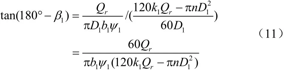
而当叶片进口相对水流角β1<90°时,对应的设计流
量小于临界流量Qr<Qc,有

由式(11)、式(12)知,叶片进口相对水流角与设计计算流量存在一一对应的关系;即给定一设计流量可以计算出合理的叶片进口安放角;反之,给定叶片进口安放角可以反求出与该进口安放角匹配的高效点流量(本文视高效点流量与设计计算流量相同)。本文选取了4个不同的进口安放角,即60°,72°,90°,105°为研究对象,计算不同进口安放角对应的设计流量,分别为83.6,90,99.2,108.6 m3/h,并建立4个不同进口安放角的叶轮模型,采用数值模拟的方法,与理论计算结果进行对比,验证上述表达式的正确性;并且对叶片进口安放角对透平性能的影响进行分析。
1.3 出口安放角的确定
设液体流出透平叶轮时绝对速度为法向出口,即α2=90°,如图3所示。此时出口相对水流角β2满足式(13)。

又

式中β2为出口相对水流角,(°);vm2为出口绝对速度的轴面分速度,m/s;u2为出口圆周速度,m/s;A2为叶轮出口实际轴面液流过水断面面积,m2。

图3 出口速度三角形Fig.3 Outlet velocity triangle
对上文设计流量,分别计算4个叶轮出口相对水流角。本文不考虑液体在叶轮出口处的相对滑移,设出口安放角βb2与出口相对水流角β2相等。叶片进口安放角60°,72°,90°,105°对应的中间流线处的出口安放角分别为40.5°,43°,45°,48°。
1.4 透平专用叶轮模型的建立
叶轮出口直径、轮毂直径、口环长度、叶片进口宽度与原型泵叶轮均相同。透平专用叶轮叶片数为11片,进口边厚度为5 mm,出口边厚度为2 mm,叶片厚度按线性变化。对叶片进、出口边分别以厚度的1/2为半径倒圆,叶片进、出口安放角分别取上文数值。采用ANSYSBladeGen软件,输入流道几何参数,划分叶片进、出口边,叶片安放角从进口到出口按照线性规律变化,叶片包角自然形成[29],建立透平叶片三维模型。将叶片三维模型导入到NX软件中,在NX软件中完成叶轮前、后盖板三维造型,生成完整的叶轮三维模型,如图4所示。制作叶片进口安放角βb1=72°的试验叶轮,如图5所示。

图4 具有不同叶片进口安放角的泵作透平专用叶轮三维模型Fig.4 3D models of special impellers using in turbine mode of pump-as-turbine with different blade inlet angles

图5 叶片进口安放角为72°的试验叶轮Fig.5 Test impeller with 72° blade inlet angle
2 泵作透平内部流动数值计算方案
采用NX软件分别对4台装有不同叶轮的透平进行三维建模及装配,建立了包括蜗壳、叶轮、尾水管、前泵腔和后泵腔5部分在内的透平全流道三维模型,如图6a所示,并在蜗壳进水段与尾水管出口段分别作一定延伸以保证在数值计算中获得较稳定的进、出口流态。在ANSYS ICEM中对各部件进行网格划分。与非结构化网格,结构化网格的生成速度快,质量便于控制。本文选用六面体结构化网格对全流道进行网格划分,同时对叶片表面、叶片进、出口边、盖板表面、蜗壳隔舌、蜗壳及尾水管过流表面等进行了边界层划分,图6b为叶轮网格。对网格无关性进行了研究,当网格数在100万以上时,透平扬程、扭矩和效率偏差均在0.5%以内,因此本文用于计算的网格在100万以上较合适。
本文基于ANSYS CFX软件平台对泵作透平的内部流动进行数值计算。选用20 ℃的清水作为流体介质。采用多重坐标系,叶轮流场在旋转坐标系中计算,其余流道在静止坐标系中计算,动静交接面设置为Frozen Rotor模式;采用标准k-ε湍流模型,近壁区应用标准壁面函数,固壁面采用无滑移边界条件,叶轮的旋转速度设为1 500 r/min,过流表面粗糙度按实际加工精度设置为50 μm,收敛残差标准为0.000 001。设置质量流量进口、压力出口边界条件,通过给定不同流量,计算得到透平不同工况运行时的性能参数。

图6 泵作透平全流道三维模型及叶轮网格Fig.6 3D model of whole flow passage of pump-as-turbine and mesh of impeller
3 数值计算试验验证
为验证数值计算的正确性,搭建了开式液力透平试验台,如图7所示,对βb1=72°的透平专用叶轮进行试验。透平所需的高压液体由一台增压泵提供,透平叶轮将液体压力能转换为旋转机械能。采用电涡流测功器(Electric eddy current dynamometer)测量和消耗透平产生的能量,通过自动控制系统使透平旋转速度恒定。在透平的进、出口分别安装压力变送器以测量进、出口压力,在透平进口管路中安装涡轮流量计测透平进口流量。通过改变增压泵转速,使进入透平的高压液体具有不同的能量,实现透平进口能量的调节,得到透平不同工况运行时的性能参数,进而绘制出透平性能曲线。

图7 开式液力透平试验台简图Fig.7 Open test rig schematic of pump as turbine
试验前对试验设备进行标定,试验参照GB3216-2005进行,表2为试验所用仪器仪表及性能参数表。高效点时,试验台测量的转速、流量、扬程、扭矩和效率的不确定度分别为±0.07%,±0.5%,±0.72%,±0.4%,和±0.97%。

表2 试验所用仪表及性能参数Table 2 Parameters of instruments used in test
将数值模拟结果与试验结果进行对比,如图8所示。透平试验扬程略高于数值计算结果,试验轴功率与数值计算结果差异不大,数值计算的效率较试验效率高。在70~140 m3/h的运行区间,计算与试验效率差为3.29%~6.85%之间。数值计算的效率高于试验值的原因主要是计算中忽略了轴承和轴封等摩擦引起的损失。虽然数值计算与试验值有一定差异,但两者的变化趋势一致。因此本文采用的数值模拟方案可用于预估透平性能。

图8 透平性能数值模拟与试验对比Fig.8 Performance curves of pump-as-turbine obtained by experimental and numerical results
4 结果分析
通过对不同叶片进口安放角的叶轮进行全流场数值模拟,得到4台透平运行性能参数,绘制外特性曲线,如图9所示。从图9可以看出,4台透平外特性曲线变化趋势一致,透平的扬程与轴功率随流量增大而增加,效率先上升后下降。叶片进口安放角对透平外特性有明显的影响,随叶片进口安放角增加,高效点向大流量偏移。表3列出了4台装有不同进口安放角叶轮的透平数值计算的高效点性能参数,叶片进口安放角从60°增大到72°、90°和105°时,透平高效点对应的流量分别为85、90、100和110 m3/h。在1.2节中理论计算的设计流量分别为83.6、90、99.2和108.6 m3/h,可见4台透平数值计算最高效率点的流量均出现在理论计算设计流量附近,与理论推导结论相符,说明上文中论据合理,理论计算结果可信。同时表明采用本文推导的设计流量与进口安放角的关系式,可以实现对透平专用叶轮高效点流量的有效预测,弥补了传统选型中对泵反转后性能预测的不足。

图9 4台不同叶片安放角叶轮的外特性曲线Fig.9 Performance curves of four pumps-as-turbines with different blade inlet angles

表3 不同叶片进口安放角叶轮对应的数值预测高效点性能参数Table 3 Numerical predicted best efficiency points of pump-as-turbine impellers with different blade inlet angles
从表3可知,随着进口安放角的增大,透平最高效率值有所下降,且下降的速率增大;当叶片进口安放角从60°增大到72°时,最高效率仅相差0.68个百分点,而当叶片进口安放角从90°增大到105°时,透平最高效率仅为77.42%,下降了2.97个百分点。从图9可以看出,在小于100 m3/h的流量范围内,随叶片安放角增大,效率越低,效率曲线越陡峭,表明在该工况范围内,选用60°的叶片进口安放角,透平最高效率与平均效率较其他3台高;但在流量大于100 m3/h的工况范围内,进口安放角为60°的透平效率下降较其他3台透平快,效率曲线陡峭。上述结论可以通过图10所示的流速三角形随流量的变化加以解释。当进入透平的流量与设计计算流量不相等时,进口安放角与进口相对水流角不等,会产生叶片进口冲角。当流量大于设计流量时,对应的轴面速度由vm1增大到1mv′,圆周分速度由vu1增大到1uv′,进口相对水流角从β1增大到1β′,产生了进口冲角Δβ。当流量与设计流量偏离越远,所产生的冲角越大,由此造成的冲击漩涡等水力损失越大。因此,小流量工况下,进口相对水流角较小,随叶片进口安放角增大,进口冲角越大,叶轮内部的水力损失越大,效率越低;反之,大流量工况下,随着叶片安放角加大,叶轮内的水力损失减小,效率提高。
在泵反转作透平的应用中,应结合实际情况,给出针对性强的透平设计方案。当需要透平在较宽广的工况范围内长时间高效运行时,透平叶片进口安放角应设计在合理的范围内。针对本文案例,叶片安放角在72°时,透平最高效率可达82%以上,在80~110 m3/h的流量区间,效率均高于80%,在大流量工况时效率曲线平坦,高效区较宽。因此,综合考虑透平最高效率及高效区范围,采用本文所述比转速的泵作透平时,叶片进口安放角不宜超过90°,宜设计在大于60°且小于90°的范围内。

图10 进口流速三角形随流量的变化图Fig.10 Velocity triangle change with flow rate at impeller inlet
5 结 论
1)理论上导出了透平专用叶轮叶片安放角与设计计算流量的关系表达式;基于ANSYS BladeGen与NX软件,设计了4个不同叶片进口安放角的透平专用叶轮,当叶片进口安放角从60°增大到72°、90°和105°时,透平高效点对应的流量分别为85、90、100和110 m3/h,4台透平数值计算最高效率点的流量均出现在理论计算设计流量附近,与理论推导结论相符;导出的叶片安放角与设计计算流量关系表达式可实现对透平专用叶轮高效点流量的有效预测。
2)随叶片进口安放角增大,透平最高效率值降低,且下降的速率增大;对于比转速为193蜗壳式单级单吸离心泵反转作透平,叶片进口安放角宜设计在60°与90°之间。
[1] Williams A A, Simpson R. Pico hydro-reducing technical risks for rural electrification[J]. Renewable Energy, 2009, 34(8): 1986-1991.
[2] Elbatran A H, Yaakob O B, Ahmed Y M, et al. Operation, performance and economic analysis of low head microhydropower turbines for rural and remote areas: A review[J]. Renewable and Sustain Energy Reviews, 2015, 43(3): 40-50.
[3] Jain S, Patel R. Investigations on pump running in turbine mode: A review of the state-of-the-art[J]. Renewable and Sustainable Energy Reviews, 2014, 30(2): 841-868.
[4] Binama M, Su W T, Li X B, et al. Investigation on pump as turbine (PAT) technical aspects for micro hydropower schemes: A state-of-the-art review[J]. Renewable and Sustainable Energy Reviews, 2017, 79: 148-179.
[5] Lima G M, Luvizotto E, Brentan B M. Selection and location of Pumps as Turbines substituting pressure reducing valves[J]. Renewable Energy, 2017, 109: 392-405.
[6] 王桃,孔繁余,何玉洋,等. 离心泵用作透平的研究现状[J].排灌机械工程学报,2013,31(8):674-680. Wang Tao, Kong Fanyu, He Yuyang, et al. Researching status of centrifugal pump as turbine[J]. Journal of Drainage and Irrigation Machinery Engineering, 2013, 31(8): 674-680. (in Chinese with English abstract)
[7] Xu T, Engeda A. Performance of centrifugal pumps running in reverse as turbine: Part Ⅱ- systematic specific speed and specific diameter based performance prediction[J]. Renewable Energy, 2016, 99: 188-197.
[8] Punit S. The choice between turbine expanders and variable speed pumps as replacement for throttling devices in non-thermal process applications[J]. Energy, 2017, 123:198-217.
[9] Jain S, Swarnkar A, Motwani K, et al. Effects of impeller diameter and rotational speed on performance of pump running in turbine mode[J]. Energy Conversion and Management, 2015, 89(1): 808-824.
[10] Pugliese F, Paola F D, Fontana N, et al. Experimental characterization of two pumps as turbines for hydropower generation[J]. Renewable Energy, 2016, 99: 180-187.
[11] Fecarotta O, Carravetta A, Ramos H M, et al. An improved affinity model to enhance variable operating strategy for pumps used as turbines[J]. Journal of Hydraulic Reasearch, 2016(3): 1-10.
[12] Barbarelli S, Amelio M, Florio G. Predictive model estimating the performances of centrifugal pumps used as turbines[J]. Energy 2016, 107: 103-121.
[13] 史广泰,杨军虎,苗森春. 离心泵作液力透平叶轮出口滑移系数的解析计算方法及验证[J]. 农业工程学报,2015,36(11):66-73. Shi Guangtai, Yang Junhu, Miao Senchun. Analytical methods and verification for determining slip factor at impeller outlet of centrifugal pumps as turbines[J]. Transactions of the Chinese Society of Agricultural Engineering (Transactions of the CSAE), 2015, 36(11): 66-73. (in Chinese with English abstract)
[14] Su X H, Huang S, Zhang X J, et al. Numerical research on unsteady flow rate characteristics of pump as turbine[J]. Renewable Energy, 2016, 94(8): 488-495.
[15] Yang Sunsheng, Kong Fanyu, Qu Xiaoyun, et al. Influence of blade number on the performance and pressure pulsations in a pump used as a turbine[J]. Journal of Fluids Engineering, 2012, 134(12): 1-10.
[16] Yang Sunsheng, Liu Houlin, Kong Fanyu, et al. Effects of the radial gap between impeller tips and volute tongue influencing the performance and pressure pulsations of pump as turbine[J]. Journal of Fluids Engineering, 2014, 136(5): 1-8.
[17] 代翠,董亮,孔繁余,等. 泵作透平振动噪声机理分析与试验[J]. 农业工程学报,2014,30(15):114-119.
Dai Cui, Dong Liang, Kong Fanyu, et al. Mechanism analysis of vibration and noise for centrifugal pump working as turbine[J]. Transactions of the Chinese Society of Agricultural Engineering (Transactions of the CSAE), 2014, 30(15): 114-119. (in Chinese with English abstract)
[18] Derakhshan S, Nourbakhsh A, Mohammadi B. Efficiency improvement of centrifugal reverse pumps[J]. ASME Journal of Fluids Engineering, 2009, 131(2): 21103-21109.
[19] Derakhshan S, Mohammadi B. The comparison of incomplete sensitivities and genetic algorithms applications in 3D radial turbo machinery blade optimization[J]. Computers & Fluids, 2010, 39(10): 2022-2029.
[20] Giosion D R, Henderson A D, Walker J M, et al. Design and performance evaluation of a pump-as-turbine micro-hydro test facility with incorporated inlet flow control[J]. Renewable Energy, 2015, 78(6): 1-6.
[21] Qian Z D, Wang F, Guo Z W, et al. Performance evaluation of an axial-flow pump with adjustable guide vanes in turbine mode[J]. Renewable Energy, 2016, 99: 1146-1152.
[22] 杨军虎,龚朝晖,夏书强,等. 导叶对液力透平性能影响的数值分析[J]. 排灌机械工程学报,2014,32(2):113-118.
Yang Junhu, Gong Zhaohui, Xia Shuqiang, et al. Numerical analysis on influence of guide vanes on performance of centrifugal pump acting as hydraulic turbine[J]. Journal of Drainage and Irrigation Machinery Engineering, 2014, 32(2): 113-118. (in Chinese with English abstract)
[23] Singh P, Nestmann F. Internal hydraulic analysis of impeller rounding in centrifugal pumps as turbines[J]. Experimental Thermal and Fluid Science, 2011, 35(1): 121-134.
[24] 盛树仁. 利用水泵逆转及水轮机回收能量的研究[J]. 流体机械,1984(6):41-45.
Sheng Shuren. Research on energy recovery using reverse running pump and hydraulic turbine[J]. Fluid Mechinery, 1984(6): 41-45. (in Chinese with English abstract)
[25] Doshi A, Channiwala S, Singh P. Inlet impeller rounding in pumps as turbines: An experimental study to investigate the relative effects of blade and shroud rounding[J]. Experimental Thermal and Fluid Science, 2017, 82: 333-348.
[26] 关醒凡. 现代泵理论与设计[M]. 北京:中国宇航出版社,2011.
[27] Wang Tao, Wang Chuan, Kong Fanyu, et al. Theoretical, experimental, and numerical study of special impeller used in turbine mode of centrifugal pump as turbine[J]. Energy, 2017,130: 473-485.
[28] 王桃,孔繁余,杨孙圣,等. 泵作透平专用叶轮直径的确定及其对透平性能的影响[J]. 农业工程学报,2016,32(15):60-66.
Wang Tao, Kong Fanyu, Yang Sunsheng, et al. Determination of special impeller diameter for pump as turbine and its effects on turbine performance[J]. Transactions of the Chinese Society of Agricultural Engineering (Transactions of the CSAE), 2016, 32(15): 60-66. (in Chinese with English abstract)
[29] 王桃,孔繁余,杨孙圣,等. 叶片安放角变化规律对液力透平性能影响的研究[J]. 农业机械学报,2015,46(10):75-80.
Wang Tao, Kong Fanyu, Yang Sunsheng, et al. Effects of the blade angle distributions on performance of pump as turbine[J]. Transactions of the Chinese Society for Agricultural Machinery, 2015, 46(10): 75-80. (in Chinese with English abstract)
[30] 杨孙圣,孔繁余,陈浩,等. 叶片进口安放角对液力透平性能的影响[J]. 中南大学学报:自然科学版,2013,44(1):108-113.
Yang Sunsheng, Kong Fanyu, Chen Hao, et al. Effects of blade inlet angle on performance of pump as turbine[J]. Journal of Central South University: Science and Technology, 2013, 44(1): 108-113. (in Chinese with English abstract)
Numerical simulation and validation of effects of blade inlet angle on performance of pump-as-turbine
Wang Tao1,2, Kong Fanyu1※, Liu Yingying1, Wei Qineng3
(1. Research Center of Fluid Machinery Engineering and Technology, Jiangsu University, Zhenjiang 212013, China; 2. School of Energy and Power Engineering, Key Laboratory of Fluid and Power Machinery, Ministry of Education, Xihua University, Chengdu 610039, China; 3. Chengdu Alen Precision Machinery Co., Ltd., Chengdu 610039, China)
Small and micro hydropower systems represent an attractive solution for generating electricity at low cost and with low environmental impact. The pump-as-turbine (PAT) approach is promising in this application due to its low purchase and maintenance cost. Due to that the conventional backward-curve centrifugal impellers do not effectively match the turbine’s running, the performance of the PAT is usually undesirable. Therefore, to improve significantly the performance of PAT, the method for determining the blade inlet angle that plays an important role in the energy conversion was investigated deeply, and one kind of special impeller with forward-curved blades was designed for the turbine working condition in this paper. Firstly, based on the conservation theorem of angular momentum, the relationship expression between the blade inlet angle and the design flow rate was deduced. Moreover, in order to validate the relationship expression and investigate the effects of the blade inlet angle on the performance of PAT, 4 special impellers with different blade angles were designed by using ANSYS BladeGen and NX software. The validity of numerical simulation was first confirmed through the comparison between numerical and experimental results. The 4 impellers with different blade angles were numerically investigated by use of a verified computational fluid dynamics (CFD) technique. The performance within PATs was investigated through analyzing the external characteristic curves obtained by CFD. The results show that the flow rates of 4 PATs at BEP (best efficiency point) obtained by CFD are about 85, 90, 100 and 110 m3/h while the flow rates by theoretical calculation are about 83.6, 90, 99.2 and 108.6 m3/h, respectively, as the blade inlet angle is 60°, 72°, 90° and 105°. Based on the results, the flow rate of numerical BEP is very close to that of theoretical BEP, and the flow rate of BEP increases with the enlargement of the blade inlet angles. And, the theoretical relationship expression between the blade inlet angle and the design flow rate presents the effective prediction of the turbine model operations of centrifugal pumps with special impellers. The maximum efficiency of PAT decreases with the increase of the blade inlet angle. And the drop rate of the maximum efficiency increases with the increase of the blade inlet angle. The results indicate that the calculating method of the blade inlet angle is reasonable. Smaller angle is matched with relatively lower rated flow rate while bigger angle with higher rated flow rate. The performance of PAT is better and the high efficiency range is wider when the blade inlet angle is designed in a reasonable range. Additionally, the energy loss within the impeller reaches the minimum if suitable blade inlet angle is selected. So considering the efficiency and the high efficiency range of PAT, the value of blade inlet angle is recommended in a reasonable range between 60° and 90° when the spiral volute of this high specific speed pump is used as turbine flume. This paper is very instructive to the design of the special impeller used in the PAT.
pumps; impellers; models; centrifugal pump as turbine; blade inlet angle; design flow rate; forward curved blades; performance prediction
10.11975/j.issn.1002-6819.2017.15.012
TH311
A
1002-6819(2017)-15-0098-07
2017-02-10
2017-06-10
国家自然科学基金资助项目(11602097、51379179);江苏省普通高校研究生科研创新计划资助项目(CXZZ13-0678);四川省教育厅重大培育项目
王 桃,女,四川成都人,博士生,副教授,主要从事流体机械及工程研究。成都 西华大学能源与动力工程学院,610039。
Email:mailtowangtao@163.com
※通信作者:孔繁余,男,江苏扬州人,研究员,博士生导师,主要从事流体机械及工程研究。镇江 江苏大学流体机械工程技术研究中心,212013。Email:kongm@ujs.edu.cn
猜你喜欢
水泵技术(2022年2期)2022-06-16
水泵技术(2021年5期)2021-12-31
水泵技术(2021年4期)2021-11-20
水泵技术(2021年3期)2021-08-14
水泵技术(2021年6期)2021-02-16
传动技术(2017年4期)2018-01-26
制造技术与机床(2017年6期)2018-01-19
汽车实用技术(2015年8期)2015-12-26
航空学报(2015年4期)2015-05-07
传动技术(2014年1期)2014-02-27
