
Experimental study on discharge coefficient of a gear-shaped weir
2018-11-15 03:40JingZhngQinChngQinghuZhngShuningLi
Water Science and Engineering 2018年3期
Jing Zhng,Qin Chng,Qing-hu Zhng,*,Shu-ning Li
aCollege of Water Conservancy and Civil Engineering,Shandong Agricultural University,Taian 271018,China
bRiver Management Bureau,Huaihe River Commission of the Ministry of Water Resources,Linyi 276000,China
Abstract This study focused on hydraulic characteristics around a gear-shaped weir in a straight channel.Systematic experiments were carried out for weirs with two different gear heights and eight groups of geometrical parameters.The impacts of various geometrical parameters of gear-shaped weirs on the discharge capacity were investigated.The following conclusions are drawn from the experimental study:(1)The discharge coefficient(mc)was influenced by the size of the gear:at a constant discharge,the weir with larger values of a/b(a is the width of the gear,and b is the width between the two neighboring gears)and a/c(c is the height of the gear)had a smaller value of mc.The discharge capacity of the gear-shaped weir was influenced by the water depth in the weir.(2)For type C1 with a gear height of 0.01 m,when the discharge was less than 60 m3/h and H1/P<1.0(H1is the water depth at the low weir crest,and P is the weir height),mcsignificantly increased with the discharge and H1/P;with further increases of the discharge and H1/P,mcshowed insignificant decreases and fluctuated within small ranges.For type C2 with a gear height of 0.02 m,when the discharge was less than 60 m3/h and H1/P<1.0,mcsignificantly increased with the discharge and H1/P;when the discharge was larger than 60 m3/h and H1/P>1.0,mcslowly decreased with the increases of the discharge and H1/P for a/b≤1.0 and a/c≤1.0,and slowly increased with the discharge and H1/P for a/b>1.0 and a/c>1.0.(3)A formula of mcfor gear-shaped weirs was established based on the principle of weir flow,with consideration of the water depth in the weir,the weir height and width,and the height of the gear.
©2018 Hohai University.Production and hosting by Elsevier B.V.This is an open access article under the CC BY-NC-ND license(http://creativecommons.org/licenses/by-nc-nd/4.0/).
Keywords:Experimental study;Discharge coefficient;Discharge capacity;Gear-shaped weir;Geometrical parameter
1.Introduction
A weir is one of the most commonly used hydraulic structures in open channels,with popular types of weirs being sharp-crested weirs,broad-crested weirs,and ogee weirs.Hump weirs and labyrinth weirs are also widely used all over the world.A large number of studies have reported on various types of weirs,and most have focused on the discharge coefficient.Several experimental formulas have been developed to evaluate the discharge coefficient.
In the case of sharp-crested weirs,many studies have focused on evaluating the discharge coefficient at early times.With the development of experimental methods,impacts of surface tension on the discharge capacity and the influenced area in a thin plate weir were investigated by Wang(2002).Based on the observation and analysis of experimental data,useful techniques have been proposed to prevent water from stroking the weir,which have improved the accuracy of measurement of hydraulic characteristics around the weir(Peng et al.,2002).A low-speed photographic technique has been used to record the flow characteristics upstream and downstream of a triangular sharp-crested weir,and some former discharge coefficient formulas have been improved effectively and conveniently(Bautista-Capetillo et al.,2014).As for the sharp-crested weir,the average velocity on the crest,instead of the discharge,has been used as a key parameter to establish a relationship between the water head on the crest and the geometrical parameters of the weir(Gharahjeh et al.,2015).
Many researchers have carried out studies on broadcrested weirs in China.A critical submergence method has been used to calculate the discharge over broad-crested weirs(Yu,1998).Some experimental formulas have been developed to calculate the discharge capacity with submerged flow over broad-crested weirs(Hua,1998;Lai,1998).In terms of Berezinskii's experiments,the boundary layer method has been used to analyze the discharge coefficient for streamlined broad-crested weirs(Wang and Zhang,2012).Discharge calculation formulas for ridge free weirs have also been developed(Tian et al.,2003;Shan and Qi,2008;Li et al.,2015).The critical hydraulic jump with orifice flow over a broad-crested weir has been studied as well(Yang et al.,2010).
Ogee weirs and crump weirs are commonly used in practical engineering.A comparison of different ogee weirs was carried out by the U.S.Bureau of Reclamation(USBR),and formulas for the discharge coefficient of some existing weirs with free outlets were established(Qi et al.,2002).The U.S.Army Corps of Engineers Waterways Experiment Station(WES)presented a novel type of weir called the WES weir in the 1940s,which soon came into common use.WES weirs were first applied in hydraulic structures like dams,spillways,and sluice engineering in China in the 1970s.Another type of practical weir,the crump weir,is widely used in small-and medium-sized hydraulic engineering.The range of application of crump weirs based on experiments and other researches’achievements has been analyzed(Tong et al.,2002).The discharge coefficient of this type of weir is impacted by the relative thickness and height of weirs,as well as the downstream slope,and a series of experimental formulas for calculating the discharge coefficient of different crump weirs have been deduced based on previous studies(Zhang et al.,2010).The relationship between the discharge coefficient of submerged flow and geometrical parameters of crump weirs was presented by Tullis(2011).
Labyrinth weirs,which are widely used in low water-head hydraulic structures,first appeared in the 20th century.However,systematic study of labyrinth weirs began in the 1970s.A feasible design method based on experiments was proposed by Hay and Taylor(1970).Due to the practical importance of labyrinth weirs,the USBR carried out a series of hydraulic tests before building the Uta Dam and the attached labyrinth weir,and thus a more effective design method was developed(Wang and Shu,1989).Dams with labyrinth weirs soon became popular in the U.S.and Australia.In China,the labyrinth weir has been studied and used since the 1980s and is commonly used at present.Experiments on rectangular labyrinth weirs have been carried out,and the economic advantages have been summarized,while the discharge coefficient of a rectangular labyrinth weir with free flow has also been presented(Kabiri-Samani et al.,2013).The radial basis function neural network and particle swarm optimization based equations have been applied to calculation of the discharge capacity of a triangular labyrinth weir with low errors(Zaji et al.,2015).
With regard to piano key(PK)weirs,different geometrical parameters have received much attention(Lempériˋere and Ouamane,2003).On the Goulours Dam,a spillway with a PK weir was first established,with a discharge coefficient four times larger than that of a classical linear weir(Laugier,2007).Utah State University(Anderson,2011),Lausanne Federal Polytechnic University(Ribeiro et al.,2012),and the University of Liege(Erpicum et al.,2013)carried out studies on PK weirs in succession,which focused on outflow curves and the impacts of weir geometrical parameters on the discharge capacity.These studies showed that the ratio of crest length to channel width,the relative water head,and the channel width ratio of the inlet to the outlet are the main factors in overflow.According to these studies,researchers have tried setting a fitting formula of the discharge coefficient.In China,experiments on different types of PK weirs have been conducted(Geng and Sun,2006).Based on previous studies,the discharge capacity formula of a PK weir was established through dimensionless analysis and parameter optimization(Guo et al.,2014).More recently,small-scale hydraulic structures in urban channels,including gear-shaped weirs,are increasingly used in landscape architecture.The gear-shaped weir is artistic because of its gear-like style and it is also useful in urban channel systems.This kind of weir has two main features:the gear-shaped weir consists of gears in a structure;at a low discharge,water flows through the weir between gears while no water flows over the crest of gears,and therefore,gears are used as a bridge.
However,hydraulic characteristics of gear-shaped weirs have not yet been studied.With the aim of determining the relationship between the discharge coefficient and geometrical parameters of gear-shaped weirs,a series of experiments were conducted in this study.On the basis of hydraulic mechanics of weir flow,a semi-experimental formula of the discharge coefficient was developed.
2.Experimental method
2.1.Experimental setup
Experiments were carried out at the Hydraulic Laboratory of Shandong Agricultural University.A model that included an underground reservoir,a pump,a high-head water pond,a lf owmeter,a gate valve,a tailwater pond,a model test area,and a backwater channel was established.Fig.1 shows a sketch of the test section.
2.2.Experimental model
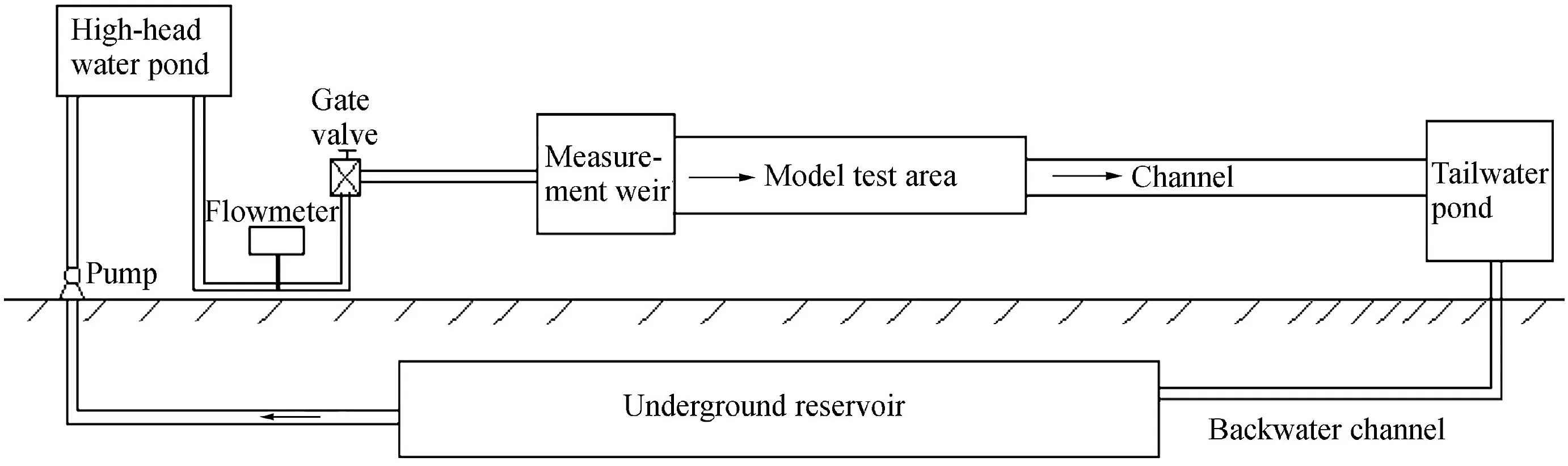
Fig.1.Sketch of experiment.

Fig.2.Geometrical parameters of weir.
A gear-shaped weir was installed in the model test area's channel,which was 0.3 m in depth and 0.5 m in width(Fig.2(a)).The detailed geometrical parameters of the gearshaped weir are shown in Fig.2(b).L is the total width of the weir(0.5 m in this experiment),P is the height of the weir(0.06 m in this experiment),d is the thickness of the weir(0.02 m in this experiment),a is the width of the gear,b is the width between two neighboring gears,and c is the height of the gear.a,b,and c are the main geometrical parameters of the gear-shaped weir,with L=n(a+b),where n is the number of gears,which were symmetrically designed.
2.3.Experimental schemes
Gear-shaped weirs,with gears of two different heights,were examined in this study:the low-gear type(type C1,with c= 0.01 m)and the high-gear type(type C2,with c=0.02 m).Experiments were carried out in two groups,with each having four schemes of different sizes.Details are shown in Table 1.
2.4.Experimental measurement
The discharge,water depth,and flow velocity were measured in this study.The flow regimes around and over the gear-shaped weir were recorded on video.Details of the measurements are shown below.
The gate valve was used to control the discharge.The value of discharge was measured with an electromagnetic flowmeter(type E-magC)produced by Kaifeng Instrument Co.,Ltd.
A digital water level indicator(type SX40-1)produced by Chongqing Huazheng Hydrometric Instrument Co.,Ltd.,was used to measure the water level in the test area,with a precision of 10-5m.The water levels upstream and downstream of the weir were measured.Each measurement section had three measurement lines(center,left bank,and right bank),and the average value represented the water depth of each section.
The acoustic Doppler velocimeter(ADV),with a downlooking probe and a side-looking probe,was used to measure the three-dimensional(3D)velocity.The ADV was produced by Nortek AS Instrument Co.,Ltd.The sampling frequency was set to 50 Hz,and the sampling time was set to 60 s in this experiment.
One thing should be emphasized:only free outflow was considered in this study.Based on the critical terms of free outflow,when the water level downstream is lower than the height of the weir,no backwater effect will occur in the test area,so free outflow can be guaranteed.
3.Results and discussion
3.1.Analysis of flow over gear-shaped weir
Fig.3 presents the profile of free outflow over the gearshaped weir.The appearance of gears has redistribution effects on the approaching flow,so the approaching flow is forced to separate into two parts:one part flowing betweengears,and the other part flowing above the gear.V21represents the outflow velocity through the gaps,V22represents the outflow velocity above the gear,H1is the water depth at the low weir crest,H2is the water depth at the high weir crest,V11is the approach velocity in the upstream section with the water depth of H1,and V12is the approach velocity in the upstream section with the water depth of H2.
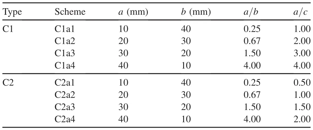
Table 1 Experimental schemes for high-and low-gear types.
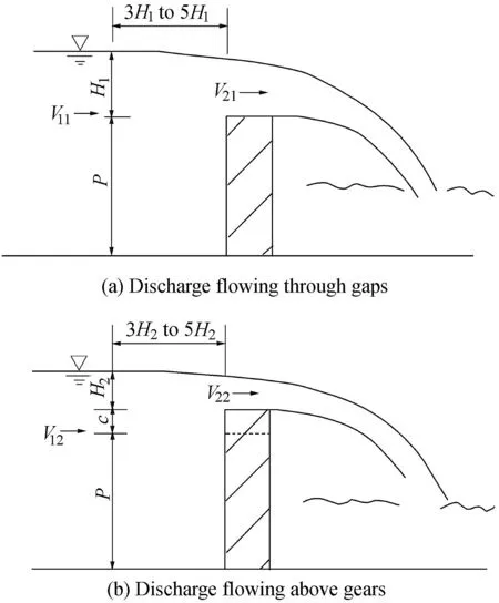
Fig.3.Sketch of free outflow over gear-shaped weir.
The discharge of the gear-shaped weir from the upstream channel can be expressed as

where Q1is the discharge through gaps,and Q2is the discharge above gears.According to the principle of weir flow,the discharges through gaps and above gears can be obtained,separately,as
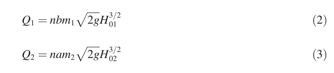
where m1is the discharge coefficient of flow through gaps,m2is the discharge coefficient of flow above gears,g is the gravitational acceleration,H01is the water head at the low weir crest,and H02is the water head at the high weir crest.H01and H02can be expressed as follows:
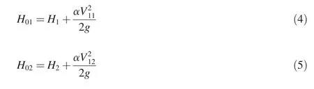
where α is the kinetic energy correction factor.Substituting Eq.(2)through(5)into Eq.(1)obtains
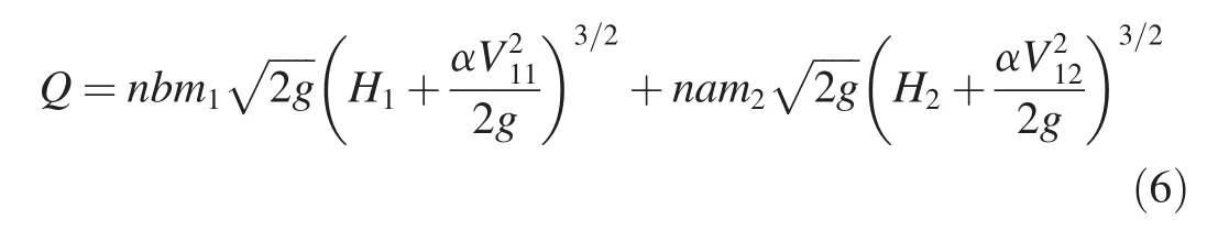
Compared with the ogee weir,classical broad-crested weir,and some other weirs,gear-shaped weirs are more complicated in terms of their geometrical features,and have stronger effects on the flow regime.Eq.(6)can be used to calculate the discharge capacity of a gear-shaped weir,but it is difficult to calculate m1and m2separately.Considering this factor,a comprehensive coefficient was used to evaluate the discharge capacity,and Eq.(6)was simplified as

where mcis the comprehensive discharge coefficient.Eq.(7)shows that the discharge capacity is influenced by the depth of water in the weir.
3.2.Results
Eqs.(1)through(7)show that m1and m2have certain relationships with geometrical parameters of the gear-shaped weir,but these relationships cannot be directly obtained with the theoretical method.Therefore,a series of experiments were carried out.
In this study,water depths and velocities in different sections of gears with two different heights,along with eight different schemes with different discharges,were measured.Each scheme included 13 discharges:5 m3/h,10 m3/h,20 m3/h,30 m3/h,40 m3/h,50 m3/h,60 m3/h,70 m3/h,80 m3/h,90 m3/h,100 m3/h,110 m3/h,and 120 m3/h.
mccan be obtained from Eq.(7),where H01is calculated with Eq.(4).With known Q,L,and H01values,mccan be calculated.
3.2.1.Discharge coefficient varying with discharge and H1/P
According to the experimental data,the relationships between the discharge coefficient and the discharge for two different heights of gears are shown in Fig.4,and the relationships between the discharge coefficient and H1/P are shown in Fig.5.
According to Figs.4 and 5,the trend of the comprehensive discharge coefficient(mc)against the discharge or H1/P can be described as follows:
(1)For type C1,when the discharge is less than 60 m3/h and H1/P<1.0,mcsignificantly increases with the discharge and H1/P.Then,with further increases of the discharge and H1/P,mcshows insignificant decreases and fluctuates within small ranges.For instance,in scheme C1a1,the calculated results of mcare 0.4231 for the discharge of 30 m3/h and H1/P of 0.6928,0.4300 for the discharge of 40 m3/h and H1/P of 0.8226,0.4252 for the discharge of 60 m3/h and H1/P of 1.0710,and 0.4097 for the discharge of 90 m3/h and H1/P of 1.4200.
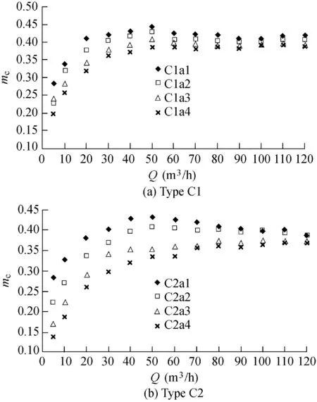
Fig.4.Relationships between discharge coefficient and discharge.
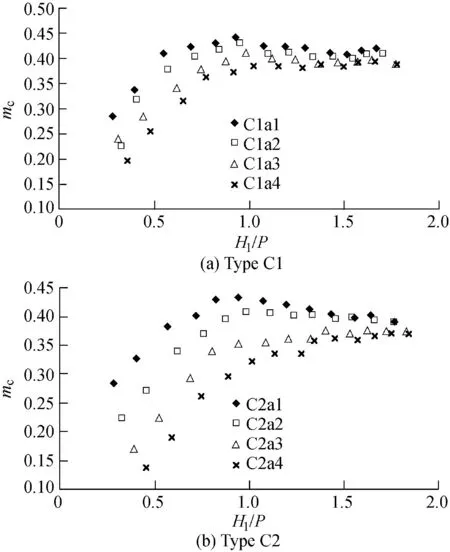
Fig.5.Relationships between discharge coefficient and H1/P.
(2)For type C2,when the discharge is less than 60 m3/h and H1/P<1.0,mcsignificantly increases with the discharge and H1/P.When the discharge is larger than 60 m3/h and H1/P>1.0,mcslowly decreases with the increases of the discharge and H1/P in schemes C2a1 and C2a2 with a/b≤1.0 and a/c≤1.0.However,mcslowly increases with the discharge and H1/P in schemes C2a3 and C2a4 with a/b>1.0 and a/c>1.0.For instance,in scheme C2a1,the calculated results of mcare 0.4024 for the discharge of 30 m3/h and H1/P of 0.7177,0.4289 for the discharge of 40 m3/h and H1/P of 0.8240,0.4262 for the discharge of 60 m3/h and H1/P of 1.0692,and 0.4050 for the discharge of 90 m3/h and H1/P of 1.4328.However,in scheme C2a4,the calculated results of mcare 0.3574 for the discharge of 70 m3/h and H1/P of 1.3440,and 0.3587 for the discharge of 90 m3/h and H1/P of 1.5728.
(3)Comparison between Fig.4(a)and(b)shows that,with the same discharge and width of gears,mcis influenced by the height of gears,and it is relatively larger for the low-gear type.
3.2.2.Discharge coefficient varying with a/b and a/c
The ratio of a/b represents the preventative effect of the gear-shaped weir.Fig.4 shows that the ratios of a/b and a/c have a strong impact on mcat lower discharge and smaller H1/P values.With the increases of the discharge and H1/P,this impact weakens.For the same discharge,the weir with larger values of a/b and a/c has a smaller value of mc.
3.2.3.Comparison of discharge capacity between gearshaped weirs and linear weirs
To further study the discharge capacity of the gear-shaped weir,a linear weir,with the same height(0.06 m)and width(0.5 m)as the gear-shaped weir,was used in the experiments.The water depth at the crest of the weir and the approach velocity were measured.The discharge magnification ratio(S)was defined to describe the different discharge capacities of these two types of weirs.S is the ratio of the discharge of the gear-shaped weir to that of the linear weir with the same water depth at the crest of the weir.It can be calculated with Eq.(8)as follows:
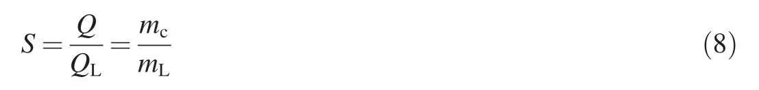
where QLis the discharge of the linear weir,and mLis the discharge coefficient of the linear weir.According to the measured data,the calculated results of S for different experimental schemes are listed in Table 2.
As shown in Table 2,all values of S are below 1.0,meaning that,with the same H1/P,the discharge capacity of the gearshaped weir is lower than that of the linear weir.The reason for this phenomenon is that,for the gear-shaped weir,the gear has a water-blocking effect,and the effective flow area is reduced.However,this new kind of weir is not designed for a stream with large discharge,and it has its own application conditions.
3.3.Calculation of discharge coefficient
Using a statistical method and the measured data,an experimental formula for the discharge coefficient can be derived as follows:
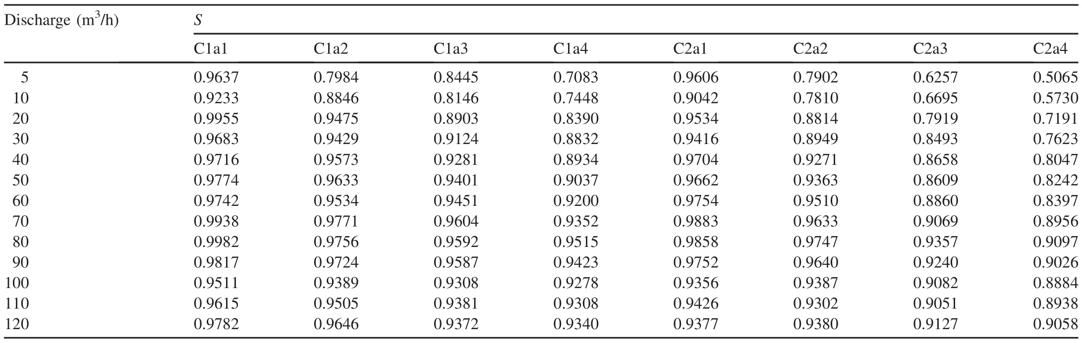
Table 2 Calculated results of discharge magnification ratios.
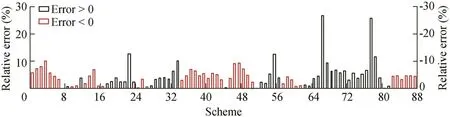
Fig.6.Error histogram of mcof gear-shaped weir.
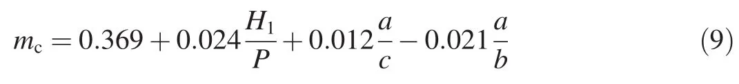
It should be mentioned that when the discharge is 5 m3/h or 10 m3/h,the water level is below the crest of the weir,so these cases have not been taken into consideration when deducing Eq.(9).Eq.(9)can be used when H1>c.
Statistical analysis shows that Eq.(9)has a correlation coefficient r of 0.725,which is greater than the allowable minimal value of the correlation coefficient,with the value of 0.273,at the significance level of 0.01 and the number of observations of 88.The F value from the F-test is 31,which is greater than the critical value of 2.713 at the significance level of 0.05 and the number of observations of 88,with three independent variables.The results of the significance test are 0.001 for H1/P and 0 for a/b and a/c,meaning that these independent variables can efficiently describe the changing mc.
Through the comparison of the calculated value and measured value of mc,the error histogram is plotted in Fig.6.Fig.6 shows that schemes with the absolute values of relative errors less than 5%and 10%account for 65.9%and 92.1%of all the schemes,respectively,while schemes with the absolute values of relative errors greater than 20%only account for 2.2%of all the schemes.Thus,it can be proven that Eq.(9)has a high accuracy in calculating mcof the gear-shaped weir.
4.Conclusions
An experimental study was performed to investigate gearshaped weirs,and the following conclusions were drawn:
(1)Eq.(7)can be used to calculate the discharge capacity over the gear-shaped weir under the condition of free outflow,and the comprehensive discharge coefficient(mc)is taken into consideration in this formula.
(2)mcis influenced by geometrical parameters of the weir,including H1/P,a/c,and a/b,and the relationship was derived in this study.This formula can be used when the water level exceeds the height of gears,i.e.,H1>c.
(3)For type C1 with the gear height of 0.01 m,when the discharge was less than 60 m3/h and H1/P<1.0,mcsignificantly increased with the discharge and H1/P;with further increases of the discharge and H1/P,mcshowed insignificant decreases and fluctuated within small ranges.
(4)For type C2 with the gear height of 0.02 m,when the discharge was less than 60 m3/h and H1/P<1.0,mcsignificantly increased with the discharge and H1/P;when the discharge was larger than 60 m3/h and H1/P>1.0,mcslowly decreased with the increases of the discharge and H1/P for a/b≤1.0 and a/c≤1.0,but slowly increased with the discharge and H1/P for a/b>1.0 and a/c>1.0.
(5)With the same discharge,weirs with larger values of a/b and a/c have smaller mcvalues.Though the discharge capacity of a gear-shaped weir is lower than that of a linear weir with the same height and width,as a landscape structure in an urban channel,the gear-shaped weir has its own application conditions.
In engineering practice,a gear-shaped weir has many other complicated geometrical parameters that have not been discussed in this paper.Moreover,only free outflow was considered in this study.More experiments with different geometrical parameters and submerged outflow conditions will be subjects for further research.
 Water Science and Engineering2018年3期
- Water Science and Engineering的其它文章
- Application of a hybrid multiscalar indicator in drought identification in Beijing and Guangzhou,China
- On relationship between curve numbers and phi indices
- Analysis of influence of observation operator on sequential data assimilation through soil temperature simulation with common land model
- Common effluent treatment plant(CETP):Reliability analysis and performance evaluation
- Disinfection of dairy wastewater effluent through solar photocatalysis processes
- Numerical study of hydrodynamic mechanism of dynamic tidal power