
Mobility matrix of a weakly coupled parallel multi-DIM isolator based on axial force solution①
2020-10-09 07:38LiDesheng李德胜YuJiangtaoHuangBaowangLiZhanxianWangZhijun
High Technology Letters 2020年3期
关键词:李德
Li Desheng(李德胜), Yu Jiangtao, Huang Baowang, Li Zhanxian, Wang Zhijun②
(College of Mechanical Engineering, North China University of Science and Technology, Tangshan 063210, P.R.China)
Abstract
Key words: mobility matrix, weak-coupling, parallel multi-dimentional (multi-DIM) isolator, axial force, mobility power flow
0 Introduction
Parallel multi-dimentional (multi-DIM) isolator is a special kind of vibration isolator, which can be decomposed into two end-platforms and the isolation limbs. Parallel multi-DIM isolator may be used in some application fields where traditional isolator cannot be used due to limitation of the complexity of vibration, especially when the vibration occurs in several dimensions simultaneously. This characteristics has attracted the interest of many researchers[1,2].
A parallel mechanism is designed in such a way that all the components including the outer framework are subjected only to tensile-compressive forces, but not to flexing, thus eliminating the need for any special machine foundation. In other words, this rigid, self-contained structure enables its capabilities to be independent of the qualities of its foundation so that it can be mounted on a movable platform.
Thanks to these structural properties, Stewart platform has gained more popularity in multi-DIM vibration isolation applications[3-8]. Hanieh[9]investigated the application of the Stewart platform with flexible joints in the active vibration isolation and damping of the sensitive equipment. Each leg of her Stewart platform consisted of a voice coil actuator, a force sensor and two flexible joints. In the field of large amplitude vibration control, Cheng et al.[10]and Ren et al.[11]studied the vibration control of the Stewart platform on flexibly supported structures. Their work was further developed by Lu et al.[12]later, and the field model experiments manifested the effectiveness of the Stewart platform in isolating the vibration and improving the positioning and orientating accuracy.
Apart from the Stewart platform, parallel mechanism with lower-mobility is also often used in multi-DIM vibration control. In Refs[13,14], a 3-axis active vibration isolation system with pneumatic actuators using modified zero-power control was developed. In Ref.[15], a 3-PUPU dual parallel manipulator for both rough positioning and active vibration isolation in a wide-range workspace was presented. In Ref.[16], the dynamic modeling and efficient modal control of a planar parallel manipulator with 3 flexible linkages actuated by linear ultrasonic motors was addressed.
However, strong-coupling always makes the practical isolation performance not up to expectations, especially for higher-mobility cases[17]. In view of this, a mobility matrix modeling strategy of a weakly coupled parallel multi-DIM isolator based on axial force solution is proposed. Numerical simulations are given to prove the validity of the established mathematical model via mobility power flow method. Experimental results are also given to demonstrate the isolation performance.
This paper is structured into following sections: axial force solution of limbs is solved by means of Screw theory in Section 1. Then, mobility matrix of weakly coupled parallel multi-DIM isolator are investigated based on the axial force solution in Section 2. In Section 3, the total mobility power flow together with response on flexible foundation, including velocity and force at bottom spherical joints is simulated. Section 4 presents a multi-DIM vibrational experiment to validate the modeling strategy for mobility matrix and the mobility power flow.
1 Axial force of weakly coupled parallel multi-DIM isolator
1.1 Structure description
The titled multi-DIM isolator can be obtained by adding spring and damping elements to 6 limbs of the ontology as shown in Fig.1(a). Spherical jointsB1-B3are distributed uniformly in a circle whose radius isr1, spherical jointsA1-A6in a circle whose radius isr2. Top view with coordinate systemo-xyz, in whichz-axis assuming the same direction as gravity, is shown in Fig.1(b). The damping performance is simulated in Ref.[18].
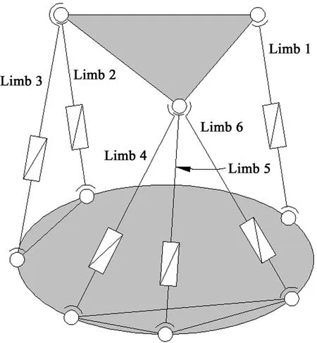
(a) Ontology of the isolator
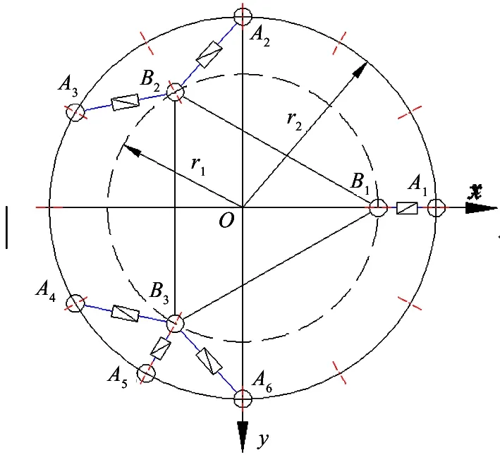
(b) Sign convention and coordinates systems
1.2 Axial force solution
Axial forces of 6 limbs can be expressed by force spinor. Considering balance of up platform, sum of 6 force spinors should be equal to 6-dimension forces acting on up platform. So the spiral equation can be written as
(1)
S/i=Si+∈S0i
(2)
Si·Si=1
(3)
Si·S0i=0
(4)
where,fiis axial force of thei-th limb.S/iis identity linear vector of thei-th limb’s axial line.FandMare vectors of principal exciting forces and moments, respectively, acting on up platform.Siis identity vector along thei-th limb,S0iis line moment of vectorSirelative to the origin of coordinate system. Balance of spiral equation can be expressed in matrix form
(5)
(6)
(7)
(8)
(9)
S0i=Ai×Si
(10)
Inverse solution of Eq.(6)-Eq.(8) denotes axial forces, which can be solved as
(11)
2 Mobility matrix modeling
2.1 Mobility matrix of rigid body source
The first substructure is rigid body source mounting at up platform, which can be regarded as a cylinder with radiusrAand center heighthA. It is assumed that the generalized exciting force acting at rigid body center, force vectorFSand response velocity vectorvScan be denoted as
FS=[Fx,Fy,Fz,Mx,My,Mz]T
(12)
vS=[vx,vy,vz,wx,wy,wz]T
(13)
Force and velocity response vectors at up spherical joints in coordinate systemo-xyzcould be marked as
(14)
(15)
(16)
(17)
For convenience, local coordinate systemO-UVPis created at up end of limb, whose origin is located at the spherical joint center. Axes of the local coordinate system are coincident with or perpendicular to limb when the isolator is in continuous motion state, as shown in Fig.2.
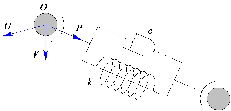
Fig.2 Local coordinate system created at up end of limb

(18)
(19)
(20)
(21)
Mobility matrix equation of rigid body source can be determined according to rigid body dynamics theory
(22)
where,αis mobility matrix of the rigid body source.
2.2 Mobility matrix of absorber limb
The second substructure is absorber limb. The moments appearing in spherical joints could be transformed into general forces because torque couldn’t be transferred through the rotational degree of freedoms (DOFs). Therefore, an absorber limb consisting of spring and damping mounted in parallel can be regarded as completely rigid in lateral, and could be molded as a complex stiffness spring. Considering the continuity of velocity and the equilibrium of force at the interface between two adjacent substructures, input variables of absorber limb must be equal to the output variables of rigid body source. Both ends of the absorber limb could be defined as input and output terminals represented by superscripts (1) and (2), respectively. Input force and velocity vectors at up end (1) in local coordinate system can be expressed as
(23)
(24)
(25)
(26)
Mobility matrix equation of absorber limb can be rearranged as
(27)
where,βis mobility matrix of absorber substructure.
2.3 Mobility matrix of flexible foundation
The third substructure is the flexible foundation, which could be molded as a clamped thin circular plate with concentrated masses at bottom spherical joints to simulate the pre-stressed effect of rigid body source under stationary and initial state. Combining 6 bottom spherical points into a module, mobility equation of flexible foundation can be described as
vC=γFC
(28)
where,γis driving force mobility matrix of the flexible foundation, which can be deduced from modal analysis[19,20].
2.4 Mobility matrix of the multi-DIM isolator
For the titled isolator, the continuity conditions of force and velocity must be satisfied. It means that the force and the velocity at interface between any 2 adjacent substructures could be described as
(29)
(30)
(31)
Mobility matrix equation of the whole isolator can be deduced by sequential multiplications of Eqs(22), (27) and (28). Velocity response vectorvSat rigid body center, velocity and force response vectorsvCandFCat 6 bottom spherical joints on flexible foundation could be obtained by recombining 3 mobility matrix equations
vS=(α11+α12Θ)FS
(32)
vC=-γΞΘFS
(33)
FC=-ΞΘFS
(34)
Ξ=(β22+γ)-1β21
(35)
Θ=(β12Ξ-α22-β11)-1α21
(36)
The mobility matrix of multi-DIM isolator can be written asΓin following equation
(37)
Mobility power flows into rigid body source and flexible foundation could be calculated as
(38)
(39)
where, superscriptHrepresents Hermitian transpose and conjugate of vector or matrix.
3 Numerical simulation and analysis
Assume amplitudes vector of the generalized exciting force acting at mass center of rigid body source is [1, 0, 1, 0, 1, 0]Tand the exciting frequency is 120 Hz. Geometric and material parameters of the isolator are given in Table 1.
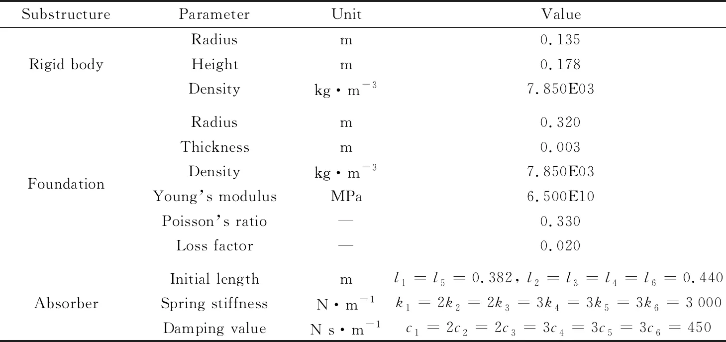
Table 1 Geometric and material parameters of the multi-DIM isolator
Driving point mobility matrix of the flexible foundation can be obtained according to Ref.[1]. Transverse velocity and force responses at bottom spherical joints can be solved as shown in Fig.3 and Fig.4.
It can be observed from Fig.3 and Fig.4 that transverse velocity and force responses are ellipse in complex plane, which suggests that velocity and force response at bottom spherical joints are periodically fluctuant and the amplitude approximates to a constant. However, for the response at spherical jointA1, the ellipses of velocity and force in complex plane, show as an obvious distortion. The reason is that limb 1 is a single opened chain with more difficulty of decoupling. The spherical jointsA2-A6belong to limbs 2-6 with one or two loops, which makes the hybrid single opened chain with less difficulty of decoupling.
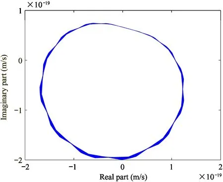
(a) Joint A1
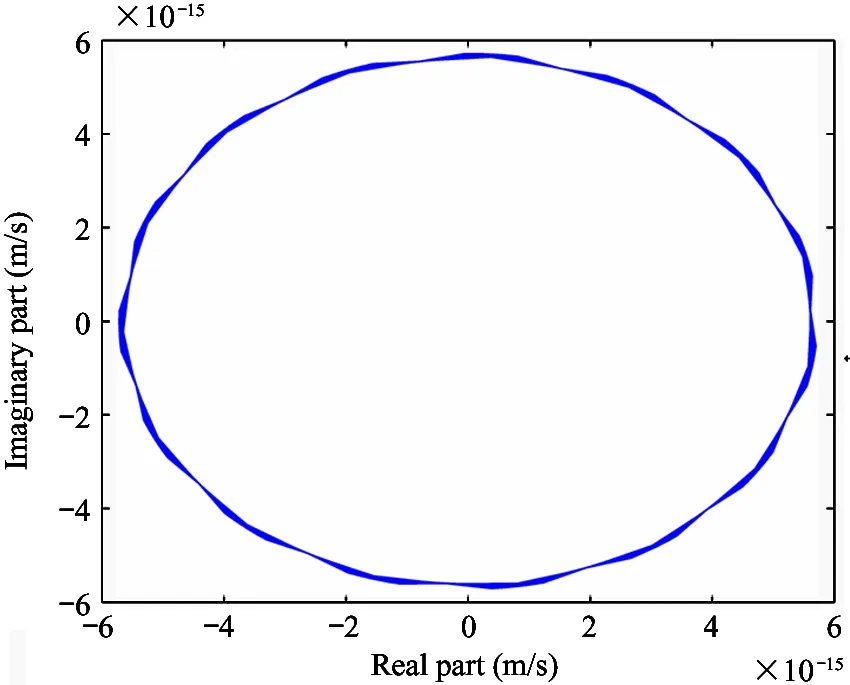
(b) Joint A2
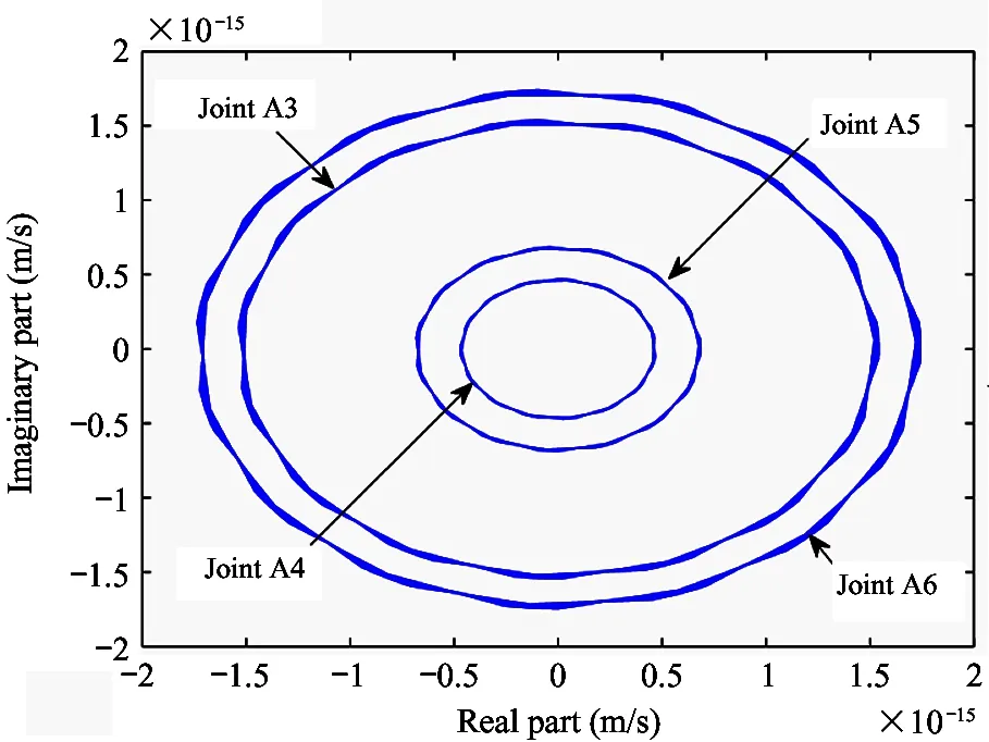
(c) Joint A3-A6
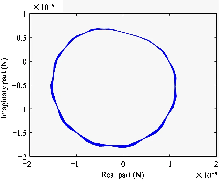
(a) Joint A1
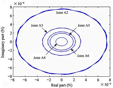
(b) Joint A2-A6
Fig.5 shows axial forces of 6 limbs. It can be seen from the plots that periodicity of axial force is constant with the exciting force because the ellipse outline fluctuates smoothly. However, the axial force is not simply harmonic due to the ellipse is inclined. Numerical migration between geometry center and origin suggests that the amplitude of axial force is not a constant and axial force is nonzero at balance position.
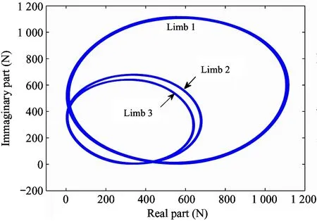
(a) Limb 1-3
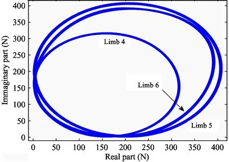
(b) Limb 4-6
4 Experimental validation
4.1 Experimental design
Prototype is manufactured as presented in Fig.6 together with the test site. It is necessary to declare that no case of 6 dimensional vibration occurs simultaneously in practical environment. Objective of the experiment is to verify the correctness of mobility matrix modeling strategy based on the axial force solution. Table 2 shows the arrangement of hammer and accelerators correspondingly.
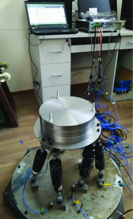
Fig.6 Prototype of multi-DIM isolator and experimental setup
Table 2 Arrangement for hammer and accelerator of multi-DIM isolator experiment
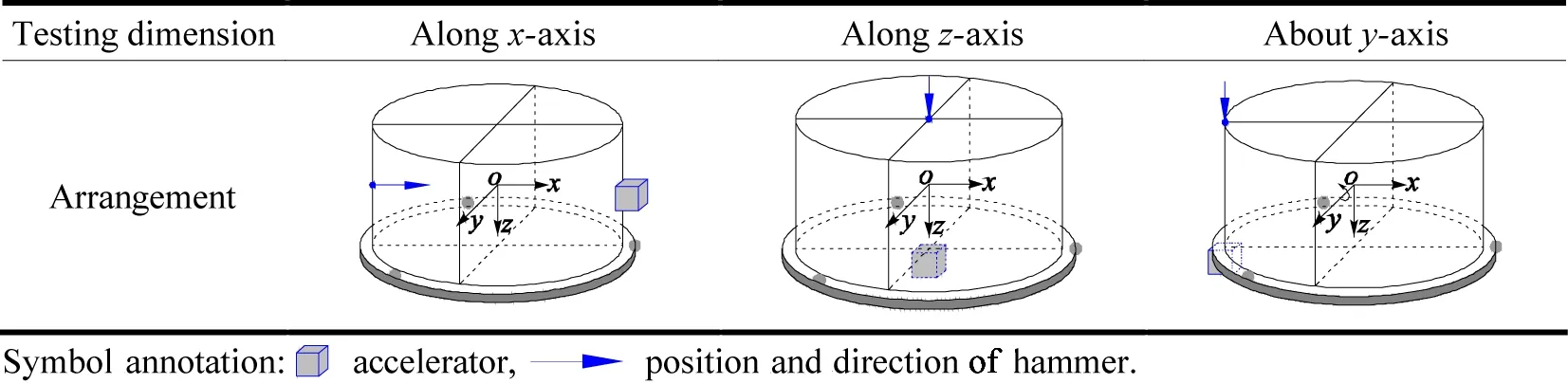
The force and the acceleration alongx- andz-axis can be measured directly. The moment and the angular acceleration abouty-axis could be calculated by combining with the measured signals as
My=FrA
(40)
αy=a/rU
(41)
where,Myandαyare moments and angular accelerations,rAandrUare the radius of rigid body source and the distribution circle of spherical pairsB1-B3in up platform. Mobility power flowing into the isolator can be calculated by cross power spectra densityGFa. Force (moment) and (angular) acceleration signals at upper end of each limb can be converted according to Table 3.

Table 3 Conversion coefficients list of generalized signals at upper end of each limb
4.2 Experimental results
Mobility power flow composed of 3 independent vibrations alongx-axis, alongz-axis and abouty-axis are shown in Fig.7. It can be seen obviously that overall trend of the input and the transmitted power flows are extremely identical. The value of power flow decreases with the increase of frequency, which means that high frequency power flow component decreases.
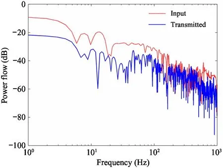
Fig.7 Experimental power flow composed of 2T-1R vibration through multi-DIM isolator
Power flow transmissibility is plotted in Fig.8. It can be found that both of experimental and numerical transmissibility are distributed perfectly flat, and trend of both transmissibility could be regarded almost as a constant in low frequency range (<5 Hz). In middle frequency range (6-92.4 Hz), deviation appears gradually. Numerical result exhibits a smooth as before, while the experimental result fluctuates remarkably, and the peaks begin to increase in quantity and intensity. It is noteworthy that more peaks appear and become obvious in higher frequency range (>100 Hz) for both results. For whole investigated frequency range, two curves indicate a favorable consistency, which verifies the correctness and effectiveness of the mobility power flow model.
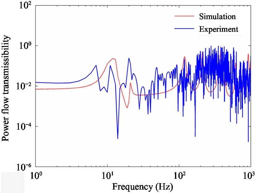
Fig.8 Comparison between the simulation and the experimental power flow transmissibility
5 Conclusions
This paper proposes an axial force solution-based mobility matrix modeling strategy for a weakly coupled parallel multi-DIM isolator. Mathematical model of mobility power flow is established via the mobility matrix and the transmissibility is simulated. Numerical results show that the response, including velocity and force, at bottom spherical joints would be influenced by the weak coupling of single opened chain. The comparison between the simulated and the experimental transmissibility shows meaningful differences. Trend of both transmissibility curves confirms well in low frequency range (<5 Hz). In middle frequency range (6-92.4 Hz), deviation appears gradually. It is noteworthy that more peaks appear and intensity becomes more obvious in higher frequency range (>100 Hz) for both results. As a conclusion, axial force solution-based strategy is a good way to obtain the mobility matrix of the titled multi-DIM isolator.
猜你喜欢
情感读本·道德篇(2022年2期)2022-04-12
红蜻蜓·低年级(2022年3期)2022-03-19
红蜻蜓·低年级(2022年2期)2022-03-19
红蜻蜓·低年级(2021年8期)2021-08-23
作文小学高年级(2020年2期)2020-12-29
早期教育(家庭教育)(2020年1期)2020-05-28
作文·小学中高年级(2020年2期)2020-04-08
金秋(2019年14期)2019-10-23
速读·上旬(2019年4期)2019-09-10
 High Technology Letters2020年3期
- High Technology Letters的其它文章
- A novel flow control scheme for reciprocating compressorbased on adaptive predictive PID control①
- Fraud detection on payment transaction networks via graph computing and visualization①
- MSONoC: a non-blocking optical interconnection network for inter cluster communication①
- Research on full-period acquisition method for diesel enginebased on self-adaptive correlation analysis①
- PRF: a process-RAM-feedback performance model to revealbottlenecks and propose optimizations①
- Research on robust control strategy of single DOF supporting systemof MLDSB based on H∞ mixed-sensitivity Method①