
Reduction of Hot Oil Carry-over in High Speed Running Turbo Application Bearings
2021-09-27 08:58KochLaabid
风机技术 2021年4期
Koch T Laabid A
(1.Department of R&D and Engineering Service;2.Department of R&D and Plain Bearing Calculation Miba Industrial Bearings,37520-Osterode,Germany)
Abstract:Tilting pad journal bearings are used in turbomachinery like turbo compressors,turbo gears,gas turbines and steam turbines.By increasing the power density,the applied loads and velocities have been increased simultaneously over the last decades.To overcome conservative operation limits,it is helpful to reduce the oil film temperatures by certain design modifications.Especially the hot oil carry-over may be reduced when design measures are taken to prevent the majority of the hot oil coming out of one pad and reaching the next pad.Beside that,this measure fresh oil should be mixed with hot oil as little as possible.The article is based on the paper“Reduction of Hot Oil Carry Over in High Speed Running Turbo Application Bearings”presented at the12thEDF/Prime Workshop,Futuroscope[1].
Keywords:Bearing;Turbomachinery;Hot oil
1 Limits of Operating Conditions
The maximum surface temperature rises over a non-allowable value (e.g.130°C) when both specific load and speed being increased (far) above the mentioned values (see Fig.1 and Fig.2).
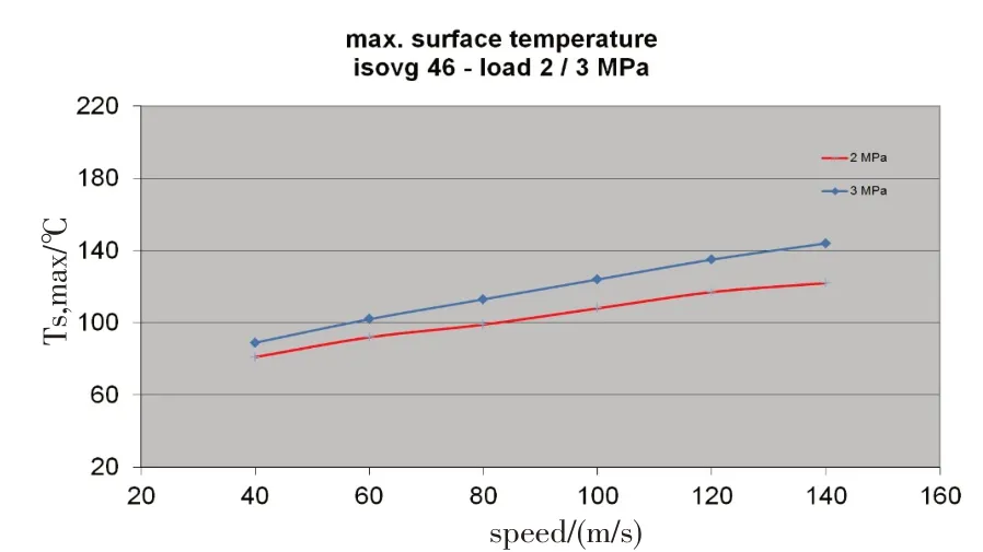
Fig.1 Example for increase of max.surface temperature of sliding pad related to circumferential speed

Fig.2 Combination of specific load and circumferential speed of a tilting pad bearing application-usual limits may be shifted in future applications
A significant reduction of the maximum pad temperature is one important option to minimize the bearing and subsequently the shaft size of the rotor-if other boundary conditions like rotor masses and natural frequencies will allow this measure.
2 Options for Optimization
It is common practice to accommodate design features to the present application.There are geometric options like:
·Size of diameter and width
·Number of pads
·Geometry of pads
·Other geometric parameters but also,oil supply measures,as the following:
·Design of lubrication nozzles
·Number of nozzles
·Distance of nozzle to the shaft
·Amount of oil
·Oil pressure
There are many possibilities to optimize the oil supply in a tilting pad bearing.For instance,an increase in efficiency is achieved by supplying more cool oil or if cooler oil is led to the highest loaded area or the hottest spots of the plain bearing.In addition,hot oil can be prevented from entering the gap between the subsequent tilting pad and the shaft.
As an example,serves Fig.3 representing different design options of oil supply unit:
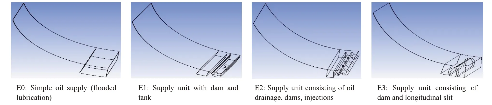
Fig.3 Different units for oil supply
3 Investigating Common and Future Design Options
To verify the efficiency of several design elements,the usual technique is to run such plain bearings in radial test rigs before starting a field test or even run them in a real application.A rather modern approach is the investigation of the three-dimensional flow of oil by using the CFD technology (see also outputs of ANSYS CFX software in Fig.4 and Fig.5).This method is a useful tool to select the most promising design features before using time consuming test rig.
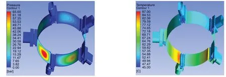
Fig.4 Distribution of temperature and oil pressure in an oil supply pocket presented by CFX simulation
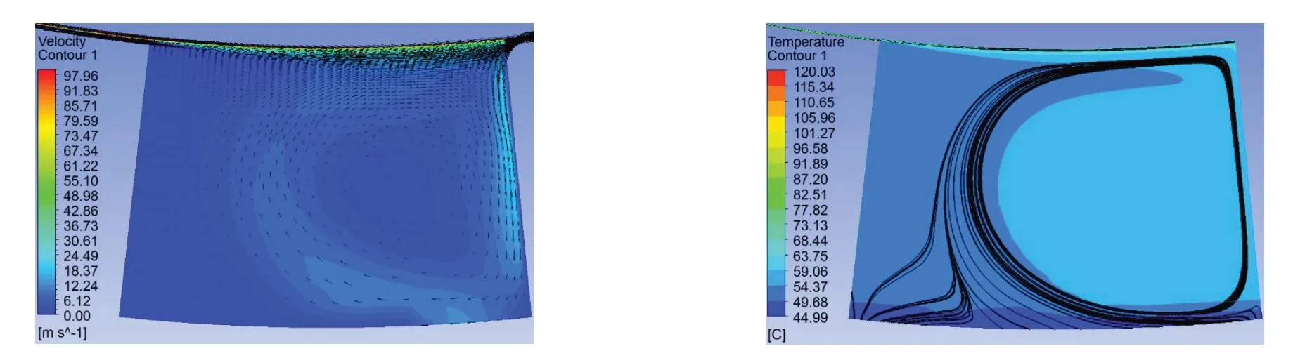
Fig.5 Distribution of velocity and temperature in an oil supply pocket according to design E0 presented by CFX simulation
The effect on bearing temperature and oil pressure can also be simulated subsequently as the following example shows:
A simple,flooded lubrication unit (see version E0)would lead to a whirl flow within the pocket due to the Couette flow effect of the shaft rotation.
The hot oil layer which is transported away from the previous pad enters the lubrication gap of the following pad.A major portion of the fresh cool oil is leaving the bearing on both sides without reaching the lubrication gap.A better tilting pad oil feed can for instance be achieved by optimizing the oil flow through the oil supply unit.
For example,each pad has at least one hot oil drainage disposed in the space between two tilting pads.This represents a first oil discharge.Furthermore,a first dam and an oil injection-which is located behind the first dam-could be included in the design.An oil jet is splashed onto the shaft to spray-wash the thin layer of hot oil from the shaft.
A mixture of the removed oil and the oil injected is being discharged by a second oil discharge unit.
The first hot oil drainage replaces known oil injections,which can be placed in spaces between tilting pads.By using hot oil drainage,the space between the two adjacent tilting pads is filled so that a large oil supply is overcome,otherwise additional frictional effects caused by turbulence can occur.Consequently,this unnecessary heating of the oil is prevented and thus performance of the bearing is improved.
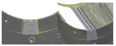
Fig.6 Three-dimensional presentation of a tilting-pad bearing;space between pads filled by means of oil drainage,dams and oil injection unit according to design E2.
A hot oil drainage can be installed in a housing ring on which the tilting pads are fixed and does not restrict the tilting motion of the individual tilting pads.Care must be taken,that the first dam does not come into contact with the shaft.For this,the first dam has to have a clearance that is at least equal to the maximum misalignment to the shaft.Injection temperatures of the oil are e.g.at 40℃-50℃.In individual cases,injection temperatures of 55℃to-60℃may occur.A lower temperature of the injected oil and a cooling of the shaft should often lead to a higher efficiency of the tilting pad bearing.
By means of the oil injecting the last residual oil on the shaft-which is dragged over from the previous lubrication gap-is broken and detached from the shaft.It then forms a mixture with the fresh supplied oil.Since a portion of the warm oil was already intercepted by the first dam,the detached hot oil from the shaft contributes to the mixture.The temperature of this mixture is therefore substantially determined by the temperature of the injected fresh oil.However,the hot oil drainage also has a second oil discharge,through which a portion of the mixture from the hot oil detached from the shaft and the injected cool oil can be discharged again.
This has several advantages.First,the portion of the hot oil that comes from the previous tilting pad,is effectively prevented from entering the following lubrication gap.In addition,the oil discharge means that more fresh oil may be injected through the oil injection.The ratio between the injected cool oil and that hot oil released from the shaft is further shifted in favor of the fresh oil.Hence,the average temperature of the mixture continues to decrease,so that a more effective cooling of the tilting pad bearing is achieved by the oil discharge.
This design of the oil discharge/drainage unit should ensure that only a very small part of the lubrication gap emerging from the previous warm oil can enter the next lubrication gap.This may be achieved by the combination of the various components of the hot oil drainages.
The space between two adjacent tilting pads can almost be completely filled by the drainage unit and fluid losses can be minimized.
Using a second dam offers the option that the mixture of the injected fresh oil and the heated oil can be-at least partially-discharged and is not used for lubrication within the next lubrication gap.Thus,a hot oil carry-over to the subsequent lubrication gap is almost completely prevented.
The necessary lubrication oil of the following lubricating gap is provided by the additional fresh oil supply.Subsequently,this one can work with lower pressure.A more laminar flow of the lubricating oil into the gap can be achieved,thereby it also prevents losses caused by friction and turbulence.
The oil injector in the axial direction may contains several nozzles for instance.By this,the oil is injected perpendicular to the shaft and the residual hot oil film on the shaft can be broken reliably and splashed off.Another phenomenon can be stated by looking at the following figure.The hot oil from the previous pad is being prevented in streaming through the gap between dam and shaft due to back flow of the fresh oil(see Fig.8).
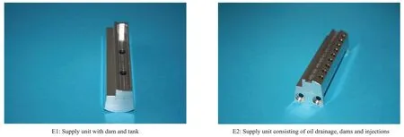
Fig.7 Examples of units for oil supply consisting of oil drainage,dams and oil injections
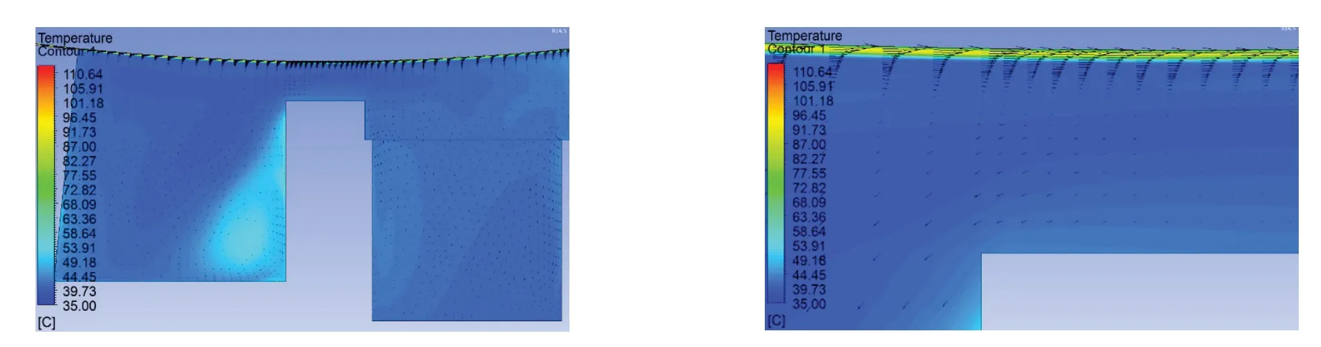
Fig.8 Distribution of temperature and oil flux vectors in an oil supply unit according to design E1.Flow back of fresh oil between dam and shaft towards previous pad
The advantages of design E1 can be combined with a separation of the oil injection e.g.by means of two separated oil injections consisting of a row of nozzles.The first oil injection represents the warm oil reduction (splashing off the hot oil) and the second represents the fresh oil supply (see Fig.9).
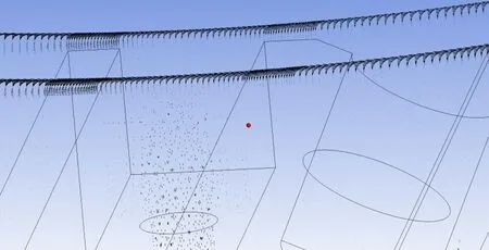
Fig.9 Distribution of oil flow in an oil supply unit according to design E2.Separation of flow back of fresh oil by means of the first oil injection
Attention has to be taken in regard to the distance of the nozzles.This distance should not be greater than e.g.one or two millimeters depending on the size of the bearing.Otherwise the single oil sprays are focused on a very limited area which cannot essentially increase the ratio of fresh and hot oil before the leading edge area(see Fig.10).
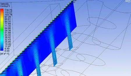
Fig.10 Local effectiveness of oil nozzles over the width of the pad
A similar behaviour of the back flow of the fresh oil can be seen for a oil supply unit with longitudinal slit according to design E3(see Fig.11)
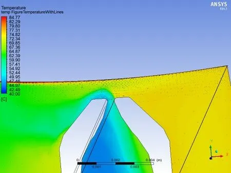
Fig.11 Hydraulic back flow of fresh oil in an oil supply unit with longitudinal slit according to design E3
4 Combining Simulation and Calculation Tools
One of the main questions now is How much can the maximum temperature be decreased,or the minimum film thickness is increased by the mentioned design measures?
For calculating the relevant data in tilting pad bearingssuch as minimum film thickness,temperature of lubrication film Miba Industrial Bearings uses a state-of-the-art software program.It has been developed by using the latest knowledge in hydrodynamic theory.The mathematical model is based on the solution of the Reynolds equation and the energy balance equation serving as a simplification of the Navier-Stokes equations.
One approach in further developing the performance of any oil flow within a tilting pad bearing is to include physical results from the simulation software (e.g.CFD from ANSYS) and transfer it to the program.Following,the model for the mixture of lubrication oil between adjacent pads can be optimized.The so-called warm-oil-reduction factor may be used for describing the efficiency of the oil supply.This usually depends on the operating conditions like oil viscosity,number of rotations,load,design of oil supply,oil supply pressure and others.In common industrial applications e.g.bearings for gas and steam turbines the factor varies somewhere between app.30%and 60%.
The factor for warm oil reduction may be increased for instance by the above-mentioned design options.When looking at the results from the calculations,it can be stated that a remarkable decrease of peak temperature has been occurred when warm oil reduction factor is increased from e.g.30%to 90%(see Fig 12).
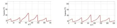
Fig.12 Temperature of lubrication film pressure calculated by Miba with warm oil reduction of 30%and with 90%.Operating conditions:n=190981/min.F=17280 N.So=0.142.
