
Foil Bearing Technology for High Speed Single Stage Air Compressors for Fuel Cell Applications
2021-09-27 08:58DaejongKim
风机技术 2021年4期
Daejong Kim
(Mechanical and Aerospace Engineering Department University of Texas at Arlington Arlington,TX,USA 76019)
Abstract:The motivation to use air foil bearings in fuel cell compressors is driven by the demand for oil-free and high-power density system to reduce system volume and weight.The characteristics of air foil bearings that realize this demand are its independency on auxiliary system and no scheduled maintenance as well as their superb performance at high speeds.However,integration of the foil bearings to the compressor needs rigorous developmental tests for the bearing to withstand high g-load during vehicle maneuver and to remain stable in rotordynamics under external destabilizing forces.This paper presents multi-pads foil bearing technology applicable to single stage high speed fuel cell air compressors.Two different multi-pad air foil bearing designs(two-pad vs three-pad)were tested using a high-speed spin test rig to identify the differences in rotordynamics responses.The two-pad bearing is superior in rotordynamics without any sub-synchronous vibration while three-pad bearing provides more uniform load capacity in all directions with less rotordynamics stability.Frequency-domain modal analyses verify the experimental observations.Axial foil bearings with 38mm outer diameter was designed and tested up to 140krpm with load capacity of 90N(1.4bar specific load capacity).Finally,a platform design of single stage 15kW fuel cell compressor with rated speed of 130krpm is proposed using the multi-pad foil bearings and axial foil bearings developed through this paper.
Keywords:Foil Bearings;Fuel Cell Compressor;Rotordynamics
0 Introduction
Operating a proton exchange membrane(PEM)fuel cell(FC) system at higher pressure allows to reduce the stack size while requires less water to achieve the same humidity as for low pressure operation [1].High air pressure increases the exchange current density which also reduces the activation loss.This ultimately results in higher power production per cell.The exiting air after a compression process would have higher temperature than the required stack temperature.Humidification and cooling of air at higher temperature is an easier task than adding water to a lower pressure air.Furthermore,the vapor pressure at 80°~90°is much higher which increases the humidity ratio.
Several studies show that optimal pressure ratio for PEM FC is around 2.5 bar which could be delivered by turbine-driven or motor-driven centrifugal compressors or positive displacement compressors [2-4].While centrifugal compressors have a narrow operating region(mass flow and pressure) with high efficiency,they overall outperform other types of compressors on volumetric power density and noise.It is desirable for air compressors for fuel cells to be oil-free because FC prohibits oil contamination in the supplied air.Therefore,air foil bearings (AFB) are sought for these applications.
Hydrodynamic AFBs do not require auxiliary component which could reduce the FC complexity and weight.AFB turbo systems with moderate DN numbers of 1.5~2 million(D is diameter of the shaft in mm and N is speed in revolution per minutes)have been demonstrated for PEM-FCs[5,6].It is noted the rotordynamics stability is the greatest challenge when the bearing shaft diameter and impeller size are reduced (with intention of increasing the speed and power density).From the well-known scaling law of rotor weight and bearing load capacity,AFB load capacity divided by shaft weight (will be called“relative load capacity”) becomes very large as the bearing size becomes smaller.As the relative load capacity becomes larger (i.e.,system size is reduced),the conventional single pad AFBs,shown in Fig 1(a),develop very high cross-coupled stiffness,which limits the maximum operating speed barely 100000rpm regardless of the shaft size (even if shaft size is reduced to below 20mm).
All the existing oil-free air compressors for fuel cells are relatively low speed (≤100000rpm) single stage with large impeller or two stage systems due to unavailability of suitable AFB technology which can achieve speeds higher than 100krpm.
Multi-pad preloaded AFB technology,of which conceptual design is shown in Fig.1(b),has been promoted at The University of Texas at Arlington (UTA) since firstly conceived by Kim [7].Recently,LaTray and Kim [8] demonstrate two-pad AFB technology applied to very small turbo expander,achieving DN over 3.2 million.Such multi-pad AFB technology enables development of single stage,very high-speed motor-driven centrifugal compressors with very small volume(weight)and high-power density.
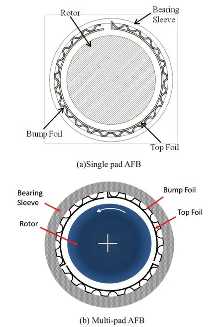
Fig.1 Conceptual image of single pad and multi-pad AFBs
Two-pad AFBs in general have better rotordynamics performance than three-pad AFBs.However,three-pad AFBs have more isotropic load carrying capacity in both horizontal and vertical directions,which may be perceived to be better for mobile applications (such as automotive fuel cells compressors and UAVs) with maneuver/shock loading in any direction.
Numerous medium sized (shaft diameters between 40 and 100mm) three-pad AFBs were designed/built/tested in the authors’laboratory for many years[9-15],and recent focus is to extend the design envelop of such AFBs to less than 25mm and also more than 100mm for industrial applications.
This paper presents recent developmental effort of multi-pad AFB technology with shaft diameter less 22mm at UTA applicable to high speed machines with speed 120~150krpm.The multi-pad AFBs were designed using non-linear rotordynamics analyses tool developed at UTA,and they found multiple industrial applications including the smallest commercial micro gas turbine generators with nominal operating speed over 134000rpm with bearing journal diameter of 21mm [16].Some materials presented in this paper were adopted from previous publications [8,17],and a new addition to this paper includes;1) comparison of experimentally measured rotordynamic performance of two-pad vs three-pad AFBs,2) frequency-domain modal analyses of two-pad and three-pad AFBs,3) recent test results of 38mm air foil thrust bearing (AFTB) achieving load capacity of 90N,and 4) single stage high-speed(over 120000rpm)fuel cell air compressor platform adopting multi-pad AFBs and novel AFTB.
1 Rotordynamic Measurement of Twopad and Three-pad AFBs
1.1 Test rotor configuration and theoretical bearing dynamics
The two-pad and three-pad AFBs are tested on a spin test rig with inertia distribution of the rotor mimicking small motor-driven compressors,and the rotordynamics responses are compared.The tested rotor-AFB system,shown in Fig.2,resembles the motor-driven compressor with overhung mass at one end of the rotor.The rotor is supported by a pair of two-pad or three-pad offset-preloaded AFBs and a pair of the six-pad AFTBs.The radial bearing span is 79.5 mm,and shaft diameter for the bearing is 19mm.The thrust runner is located at the left side of the Fwd AFB.More details of specific two-pad AFBs tested in the current paper can be found in [8].The three-pad design shares the same nominal clearance and individual bump stiffness as the two-pad design,and only difference is just the number of top foil pads.
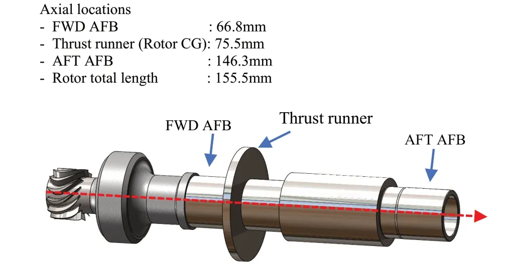
Fig.2 Test rotor mimicking motor-driven compressor
The weight of the overhung mass falls within the weight range of small radial impellers that operate at similar speeds.Calculation of static loading to the bearings indicates that the Fwd AFB takes 3.79N while the Aft AFB takes only 0.47N,practically no-load condition.Polar and transverse moments of inertia of entire rotor assembly are 0.0385g-mm2and 0.7361g-mm2.Locations of bearings and other details of the rotor components are shown in Fig 2.
Overall objective of the high-speed test is to experimentally evaluate the rotor-AFB stability up to 150krpm with two different AFB designs.The test rig is shown in Fig 3.To monitor the rotor vibration,four proximity probes in the radial direction and one proximity probe the axial direction are mounted.The figure also indicates the location of the infrared high-speed tachometer.Temperatures around the bearing sleeves are monitored using four type K thermocouples.Cooling air is supplied to the Aft AFB by feeding compressed air from the turbine shroud to the Aft bearing compartment.Fig.4 shows the overall test bed and instrumentation setup which includes a computer where real time FFT signals can be monitored and a tachometer panel that displays the rotor speed.Further details of the test rig and radial AFBs can be found in[8].
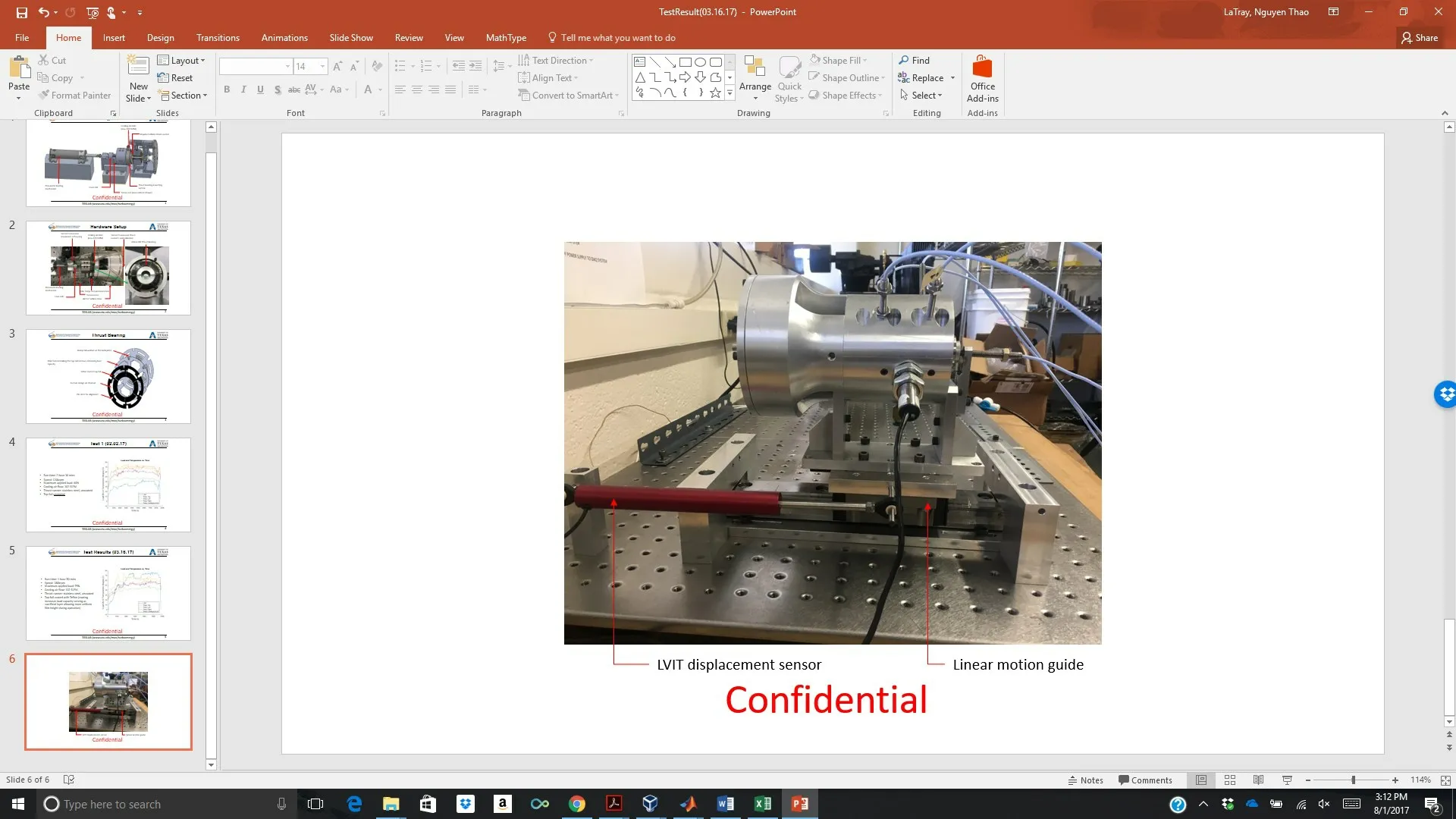
Fig.3 Test rig with sensors mounted on the housing
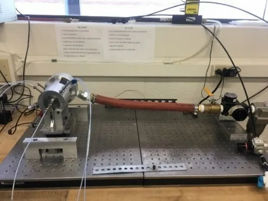
Fig.4 Photo of entire test bed
1.2 Experimental comparison between two-pad and three-pad AFBs
Both sets of experiments share the same pair of thrust bearings.Fig.5 and Fig.6 show waterfall plots from the twopad and three-pad AFBs,respectively.Two-pad AFB does not show any subsynchronous vibration.The difference in response of this system compared to one in [8] is due to small shifting of the rotor center of mass toward the Aft AFB resulting in a more favorable rotordynamics than the previous layout.Three-pad AFB shows subsynchronous vibration locked to the system natural frequency excited by the aerodynamic disturbance from the impulse turbine.The natural frequency is determined to associate with the system forward conical mode as shown in Fig.8.The natural frequency is very low,which means the low frequency whirl does not exert any damage to the bearing and dynamic load to the bearing due to the whirl is also very low.Fig.7 shows waterfall plots of rotor axial motions,and there is not much difference in overall vibration characteristics.
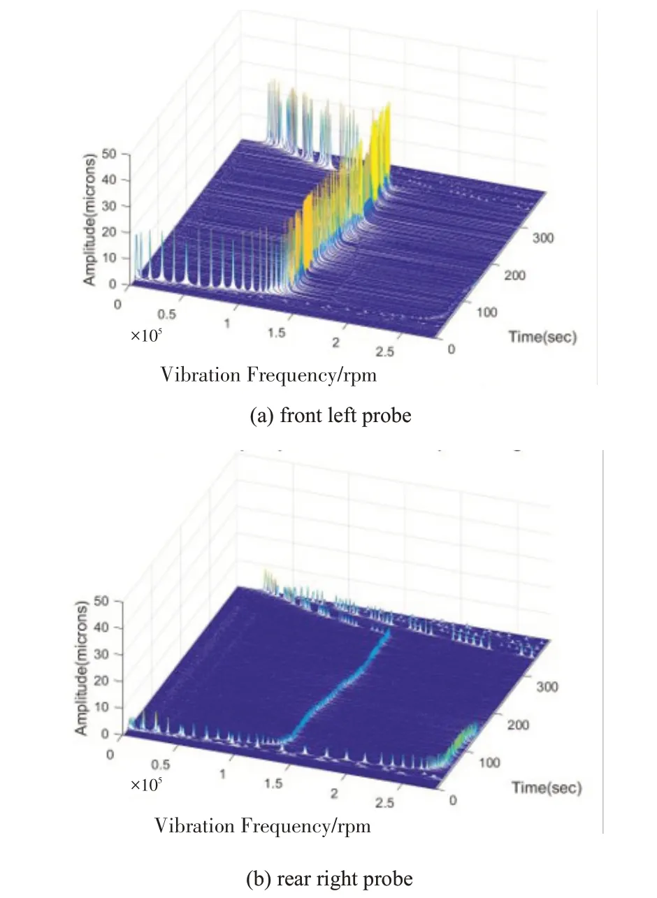
Fig.5 Waterfall plots of rotor vibration supported by two-pad bearing
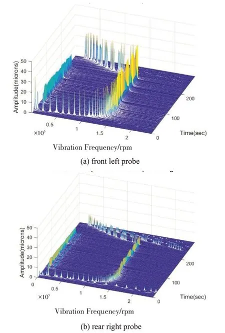
Fig.6 Waterfall plots of rotor vibration supported by three-pad bearing
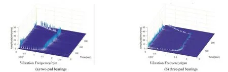
Fig.7 Waterfall plots of rotor axial vibration
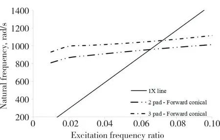
Fig.8 Natural frequency map of the forward conical mode as functions of excitation frequencies when rotor speed is 140000rpm
Simulations were performed to calculate stiffness and damping coefficients of the two AFBs at 160000rpm as a function of excitation-frequency,and their characteristics are shown in Fig.9(a) and Fig.9(b),where X is vertical direction downward (direction of gravity) and Y is horizontal direction.As shown in Fig.9(c) and Fig.10(c),two-pad AFB shows all positive modal damping for entire excitation frequencies while three-pad AFB shows negative damping at excitation frequency ratio below 0.4.
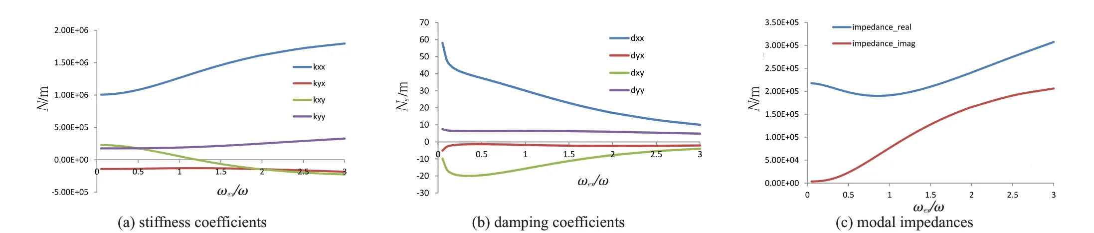
Fig.9 Stiffness and damping coefficients of two-pad AFB as a function of excitation frequency at 160krpm
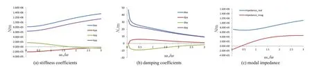
Fig.10 Stiffness and damping coefficients of three-pad AFB as a function of excitation frequency at 160krpm
The bearing temperature is normal throughout the run time as shown in Fig.11 and Fig.12.The sudden jump at the end is during touch-down when turbine flow is turned off,showing the bearing sleeve temperature increases about 10 degrees when hydrodynamic film collapses.It is worth mentioning that the cooling air to the bearings is discontinued as the turbine drive air supply valve is closed.
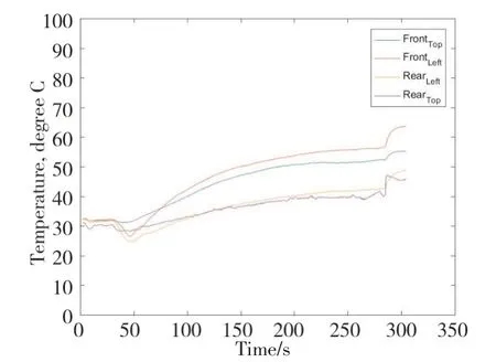
Fig.12 Temperature history of three-pad bearing
2 Axial Load Capacity of Air Foil Thrust Bearing
The test thrust bearing is a six-pad AFTB shown in Fig.13 taken before the tests.The AFTB features a three-layered structure including top foil,shim foil and back plate with bump foil welded on.The top foil material is Inconel 718 and coated with dry solid lubricant.Bump foil material is also Inconel 718.The shim and back plate are made of stainles
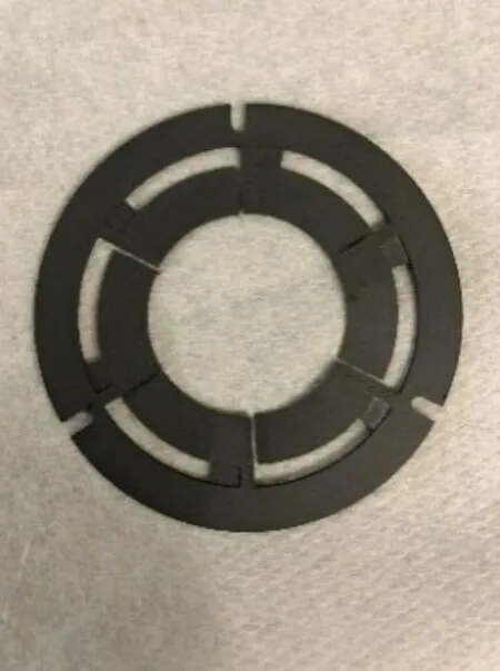
Fig.13 Photo of axial foil bearing
The bearing was tested up to 140krpm achieving maximum applied load of 90N (specific load capacity of 139kPa)after which frictional torque increases rapidly indicating partial contact between bearing and runner.Fig.14 shows temperature and load history of the test.The bearing temperature at the“left”and“top”location is 30°C higher than cooling air temperature.The bearing temperature at the“right”locations are about 18℃above cooling air temperature.This can be interpreted that the bearing film thickness is not uniform and is smallest at the“left”location making the bearing temperature at this location most sensitive to the applied thrust load.Despite small misalignment,the bearing was able to maintain the air film to counteract the applied thrust load.

Tab.1 Thrust bearing parameters
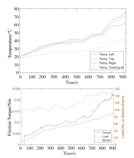
Fig.14 Test data history
Fig.15 shows collection of power loss over a range of tested speed and thrust load.Measured power loss is a torque multiplied by angular velocity of the thrust runner disc,and the torque is calculated by multiplying the measured force on the load cell connected to torque rod and the distance of the load cell from the center of thrust bearing.The predicted power loss is calculated assuming the external load is equally distributed among all the pads,and the bump height distribution is also uniform for all the pads.However,measured total bump heights distribution is 372(+/-4)microns,indicating non-uniform load distribution among the pads(i.e.,originated from manufacturing error).The wear marks distribution shown in Fig.13 also indicates non-even bump height distribution among the pads.
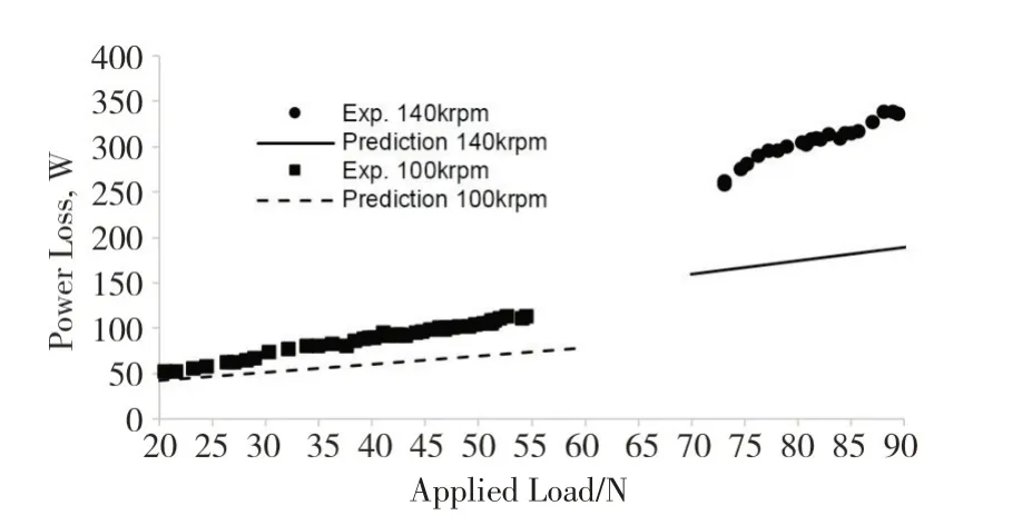
Fig.15 Power loss comparison between prediction and measurement at 140000rpm
Another main reason of large deviation of measured power loss vs prediction at 140krpm is due to runner disc wobble caused by critical speed in conical mode of the thrust runner shaft as found in[17].The conical mode of the runner shaft causes wobble of the runner disc causing unequal film thickness distribution,especially much thinner film thickness toward the outer edge.Predicted power loss in Fig 15 is calculated as an integration of shear stress on the runner surface from both Poiseuille flow and Couette flow predicted from solution of Reynolds equation.But the following simple formula for the power loss of two parallel discs gives better insight why the measured power loss at high speeds are much larger than prediction.
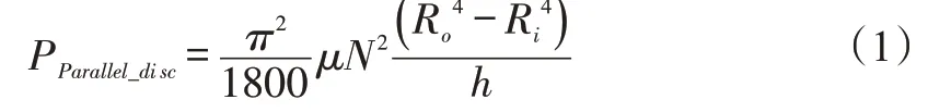
wherehis the gap between the two parallel discs and Ro and Ri are outer and inner radii of the discs.It is noted the power loss of parallel disc is proportional to Ro4/h.When wobble of the thrust runner disc is high,local film thickness toward outer radius is smaller,resulting in much larger power loss from the outer edge.Therefore,the scatter of measured power loss at low speed is mainly due to uneven bump heights among the pads (manufacturing error) and the scatter becomes larger in proportion to the applied load.The large deviation at high speeds is a combination of the manufacturing error and thrust runner wobble.
3 Fuel Cell Compressor Platform
Based on the foil bearing technology available for high speeds over 120000 rpm,a single stage high-speed air compressor with pressure ratio of 2.5 and motor power of 15kW is proposed as shown in Fig.16,where the multi-pad AFBs are directly integrated into the motor housing,allowing very compact and reduced cost.Total length of the compressor is below 200mm and outer diameter of motor housing is 100mm,and total weight is 6.9kg.Total weight of the rotating component is 644g,which allows very small gyroscopic loading to the radial AFBs.The motor cooling system is designed with liquid cooling for stator and a shaft-mounted cooling fan (environment temperature 45℃) for the bearings and motor air gap.Due to the proprietary design features of the compressor,detailed cross sections are not shown in this paper,but the compressor adopts multi-pad radial AFBs and novel AFTB.An advanced compressor seal is located between the compressor wheel and bearing compartment to reduce the axial load below 50N.
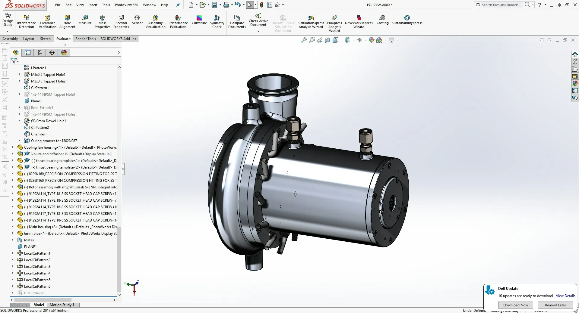
Fig.16 Single stage high speed fuel cell compressor design platform,design speed over 120000rpm
4 Conclusions
The small foil bearings and small footprint of the fuel cell air compressor are crucial to reduce total system volume and weight for the automotive fuel cell compressor applications.Two different types of multi-pad AFB designs were compared in their rotordynamics performance using a turbine-driven high-speed rotordynamics test rig.Three-pad AFB shows subsynchronous vibration locked to the system natural frequency (rigid body critical speeds) but the natural frequency is very low,even lower than the lift off speeds which is about 15,000rpm.The low natural frequency allows the subsynchronous vibration to produce very negligible dynamic force the bearing,practically no harm to the bearings.
Two-pad design provides more stable rotordynamics performance than three-pad design without showing any subsynchronous vibration.Modal impedance values calculated using perturbation method verifies the positive damping across entire excitation frequency range while three-pad AFB shows negative damping at low excitation frequencies.
Thrust foil bearing designed for the intended application shows load capacity of 90N (specific load capacity of 139kPa) at 140,000rpm.Even with +/-4 microns of bump height distribution (caused by manufacturing error),the thrust foil bearing demonstrates specific load capacity of more than 130kPa.The non-uniform bump heights and thrust runner’s conical mode of vibration is the source of large deviation of measured power loss from the simulations.
