
CCD signal acquisition and optimal digital denoise technology①
2022-01-09 02:08LiWencan李文灿WenYanWangDongYaoDalei
High Technology Letters 2021年4期
Li Wencan(李文灿),Wen Yan,Wang Dong,Yao Dalei
(*Xi’an Institute of Optics and Precision Mechanics,Chinese Academy of Sciences,Xi’an 710119,P.R.China)
(**University of Chinese Academy of Sciences,Beijing 100049,P.R.China)
(***College of Automation,Northwestern Polytechnical University,Xi’an 710068,P.R.China)
Abstract
Key words:charge-coupled device(CCD),low noise,reset noise,digital correlated double sampling,optimal filter
0 Introduction
The charge-coupled device(CCD)[1-2]is a novel type of semiconductor device developed in the early 1970s.Owing to its high sensitivity,good spatial resolution,and large dynamic range,it is widely used in industrial monitoring,image recognition,non-contact measurement,astronomical observation,space debris detection,and other fields.
The readout noise[3-5]of the CCD detector limits its energy resolution and system dynamic range.The traditional CCD signal low-noise processing technology mainly implements correlated double sampling(CDS)technology through analog devices[6-8].This technology can reduce the reset noise in the readout noise,thus,it is widely used.The main three typical CDS circuits are correlated sampling,double slope integration and clamp sampling.However,the traditional CCD video signal processing technology has some shortcomings.It is difficult to achieve the optimal suppression of CCD noise.In addition,its circuit structure is somewhat complicated,which introduces new noise.Therefore,to meet the ultra-low noise requirements of CCD detectors for astronomical observations,it is essential to extensively research and explore new technologies and methods to suppress the noise of CCD detectors.
With the continuous development of digital technology,the application of digital filtering technology to the readout system of CCD detectors has been realized.Ref.[9]proposed a digital CDS(DCDS)technology based on the digital readout technology,which removed the analog CDS(ACDS)circuit and adopted highspeed A/D and digital filtering technology to process the readout signal of the CCD detector.Ref.[10]conducted analysis and experiments on the CCD detector digital denoise system,and compared the performance of differential mean filtering and coefficient weighting based on Gaussian kernel,Laplacian kernel,etc.,the results indicated that the differential mean filtering outperforms coefficient weighting.Ref.[11]proposed a DCDS system based on a differential mean filter to process CCD signals,which showed that digital readout had better denoising performance.However,the system is imperfect and the digital filtering method does not consider the relevant characteristics of noise,which needs further improvement.
First,in this article,the source and the characteristics of reset noise are analyzed.Based on a PCIe data acquisition card,a CCD acquisition and digital noise reduction system is established and then three digital filters based on coefficient kernel distribution are also designed.Second,a CCD signal model is established,and an optimal filter is designed based on the model.Finally,the image data,generated by the experiment,is analyzed to evaluate the performance of the digital denoise method and filtering algorithm.
1 Reset noise and characteristic analysis
Reset noise[12-14]is the main noise source in a CCD camera electronic system,which is produced by the resistance thermal noise of the CCD output stage reset tube.As shown in Fig.1,when the reset pulse arrives,the reset tube is turned on and the on-channel resistance isRon.The thermal noise,generated by this resistance,will be added to both ends of the CCD output holding capacitor(C1),thus reset noise is generated.After the reset pulse has passed,the cut-off channel resistance isRoff,and the output holding capacitor is in a discharging state.BecauseRoff C1is relatively large,there is still residual reset noise on the capacitor.

Fig.1 CCD detector read circuit
The reset noiseVeand the number of its equivalent noise electronneare expressed as
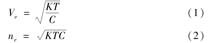
where,Kis Boltzmann’s constant,Tis the absolute temperature,andCis the capacitance.From Eq.(1)and Eq.(2),it can be seen that the reset noise and temperature are related to the size of the capacitor.
It can be realized from the generation principle of reset noise that the essence of reset noise is thermal noise.Thermal noise can be expressed as a result of a white noise,whose power spectral density is 2KTR,passing through a low-pass filter,and its power spectral density function can be expressed as

where,Swhite(w)=2KTRis the power spectral density of the white noise,andH(jw)is the first-order lowpass filter,which can be expressed as
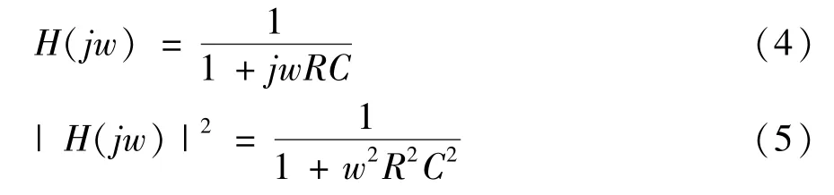
Therefore,the power spectral density function of reset noise is given by

The autocorrelation function and power spectral density of a stationary random process are related by Fourier transform.Thus,the autocorrelation function of reset noise can be expressed as

From Fig.2 it can be seen,in reset noise,the closer the sampling points are,the greater the correlation is.Therefore,when using the CDStechnique,two points closer to each other should be selected,and the noise at these two points are similar;thus,the reset noise can be suppressed by subtraction.

Fig.2 Reset noise autocorrelation function graph
2 CCD detector digital denoise system design
2.1 CCD signal digital readout technology
To suppress reset noise,ACDS is usually used to suppress it and obtain pixel information[15-18].Fig.3 shows a traditional CCD signal processing system,which comprises front-end amplification,ACDS circuit,and A/D conversion circuit.
A digital CCD denoise technology[19-22]is employed in this study.As shown in Fig.4,the digital readout system includes front-end amplification,A/D converter,digital filtering,and so on.It removes the traditional ACDS circuit,so it can effectively reduce the noise of the analog circuit.In addition,because the digital filter is at the last end of the readout system,it has a certain suppression effect on the noise generated by the amplifier,A/D converter and other circuits in the readout system.

Fig.3 CCD signal processing based on ACDStechnology

Fig.4 CCD signal processing based on DCDStechnology
2.2 Experimental platform design
In this study,a digital CCD denoise system is designed based on a PCIe data acquisition card.As shown in Fig.5,the system mainly includes a CCD detector,a gain amplifier,an analog low-pass filter,a PCIe data acquisition card and personal computer(PC).The CCD signal after low-pass filtering is transmitted to the computer,and then the digital CDStechnology is realized by digital filtering on the computer.

Fig.5 CCD digital denoise system
The system uses the PCIe9834 data acquisition card from ADlink company.As shown in Fig.6,the acquisition card has a 16-bit programmable sampling rate of up to 80 MS/s,four-channel analog input,and 1 GB on-chip storage.There are three modes,i.e.software trigger,external digital trigger,and analog trigger,and its programmable input voltage range and system error are listed in Table 1.

Table 1 PCIe9834 system noise
3 Design of optimal digital denoise algorithm

Fig.6 PCIe9834 data acquisition card
The CCD digital denoise system is mainly based on the digital filtering technology,which relies on high-speed ADCto oversample CCD signal and realizes DCDStechnology.Since the digital filter is at the end of the entire readout system,a suitable digital filter can not only suppress reset noise and obtain real pixel signals,but also suppress the noise of the entire CCD readout system.In addition,it improves the system’s signal-to-noise ratio and detection capability.
3.1 CCD model establishment
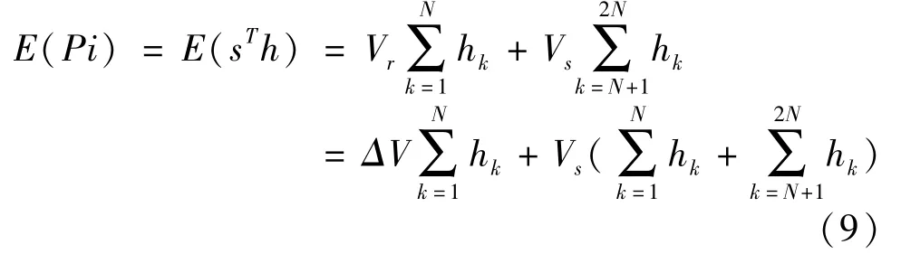
To explore the best digital algorithm in terms of denoise,CCD signal model is established(Fig.7),where,Vrrepresents the amplitude of the reference level,Vsrepresents the amplitude of the signal level,Nrepresents the number of samples of the reference level and the signal level,t(0)represents the beginning of the reference level,t(N+L)represents the beginning of the signal level,andLrepresents the number of sampling points at its transition.

Fig.7 CCD signal model
According to the principle of DCDS,the estimated value of thei-th pixel can be expressed as

where,sT=[Vr+n1,Vr+n2,…,Vr+nN,VS+n N+L+1,…,VS+n2N+L]is the sampling point,nj=[n1,n2,…,nN,nN+L+1,…,n2N+L]is the value of the noise component in the sampling point;his the coefficient of the digital filter.Piis the estimated value of thei-th pixel,and its expectation satisfiesΔV=Vr-Vs,andE(nj)=0,hence,Eq.(9)can be obtained.
Assuming thatPiis an unbiased estimate,substitutingE(Pi)=ΔVinto Eq.(9),The followings can be obtained.
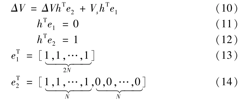
It can be seen from the derivation that the coefficients of the digital filter should satisfy Eqs(11)-(14),and the figure should meet the conditions such as center symmetry.
3.2 Kernel distribution coefficient weighting filter
Based on the analysis of the reset noise model,it can be seen that the closer the sampling point is,the greater the correlation.Therefore,the closer the point to the transition is,the greater the weight coefficient is obtained,which is beneficial to further suppress noise.Therefore,the distributed kernel is mainly used as the filter coefficient,and the difference mean filter and Gaussian weighted filter are mostly used at home and abroad.In this section,we briefly introduce these two filters,and design a hyperbolic coefficient weighting filter,whose filter shape is more consistent with the characteristics of noise.The filter with distributed kernel coefficients is as follows.
(1)Difference mean filter
The reference and signal levels of CCD signal obtained from oversampling are averaged respectively,and then subtracted as
where,2Nis the number of sampling points for both the reference and signal levels,Siis thei-th sampling point.
(2)Gaussian coefficient weighting filter
After analyzing the characteristics of the reset noise and the autocorrelation function,it can be seen from Fig.8 that the closer the sampling points are,the greater the correlation degree is.Therefore,at the transition between the reference level and signal level,the closer the point is to the transition,the greater the correlation,so the sampling data near the transition can be given a greater weight coefficient,which is conducive to further suppression noise.Therefore,Gaussian weighted filter can be used.

Here,αiis the filter weight coefficient of thei-th sampling point,and the Gaussian function is selected as its base waveform,given by

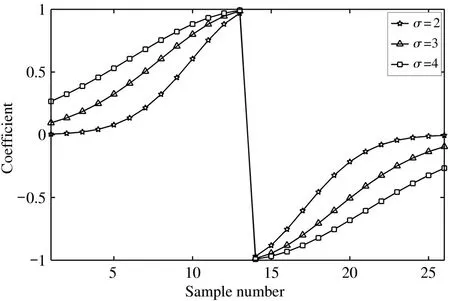
Fig.8 Gaussian weighting filter
(3)Hyperbolic coefficient weighting filter
To further suppress the noise,a hyperbolic filter(Fig.9)is designed based on the autocorrelation function graph of the reset noise.Its waveform is sharper than that of the double Gaussian coefficient weighted filter.Eq.(16)is used to calculate the pixel information,whereαiaccords with the following base waveform.

where,PandCare parameters.It can be seen from Eq.(18)that whenP=1,the filter is an average filter.As the parameterCcontinues to increase,the filter coefficient image becomes sharper.
3.3 Optimal filter
The first three filters all use a specific distributed core as the reference waveform,which has certain limitations.To obtain the optimal filter coefficient and achieve the optimal noise suppression,the size of the pixel error of CCD signal is used as a measurement standard to model and analyze it.The pixel error is expressed as


Fig.9 Hyperbolic weighting filter
Assuming thathis an unbiased estimate and substitutingsinto Eq.(19),Eq.(20)can be obtained.

where,Ris the autocorrelation function of noise.It can be seen from Eq.(20)that the optimal filter coefficienthcan be obtained by minimizingVar(Pi),and the Lagrange multiplier method is used to derive it.Eqs(11)and(12)are constraints.The process is as follows.
finally,it can be obatined
It can be seen from Eqs(24)-(26)that the optimal filter coefficient is only related to the autocorrelation of noise,so the optimal filter coefficient can be obtained based on the autocorrelation characteristics of noise.The autocorrelation characteristics of reset noise above can be analyzed.Substituting Eq.(7) into Eqs(24)-(26),the optimal filter coefficient can be obtained.The image is shown in Fig.10.
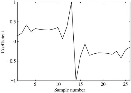
Fig.10 Optimal filter coefficient
4 Experiment results
This experiment uses C#to realize the drive and acquisition of the PCIe9834 data acquisition card(Fig.11)to realize the channel selection,sampling rate and point setting,trigger mode,and other functions.In the test mode(no photos,only readout)and uncooled experimental conditions,CCD signals were collected at a readout rate of 1 MHz and 500 kHz,respectively.To control variables,the sampling rate was set to 80 and 40 MS/s.Because of the large amount of data,the program will read the sampling points ten times through the on-chip buffer.

Fig.11 Data acquisition card control panel
After collecting the data,CCD signal is processed as follows.
(1)Extract CCD signal.A total of 590 rows of data were extracted,with 1076 pixels per row.
(2)Set the filter coefficient.For Gaussian weighted filtering and hyperbolic coefficient filtering,500 sets of different filter weighting coefficients ofσorCare generated respectively.The optimal filter coefficient is obtained by minimizing the standard deviation of the image.For the optimal filter coefficient,since the CCD readout mode is the test mode,the optimal filter coefficient based on the noise of the entire readout system can be obtained,so it has the ability to suppress other noises in the system.
(3) Digital filter.Differential average filter,Gaussian coefficient weighted filter,hyperbolic coefficient weighted filter and optimal filter are used for the CCD signal processing,then,its pixel information is calculated.Filter coefficients are shown in Fig.12,Fig.13 and Fig.14,which are the optimal Gaussian weighting coefficient,the optimal hyperbolic weighting coefficient and the optimal filter coefficient respectively.
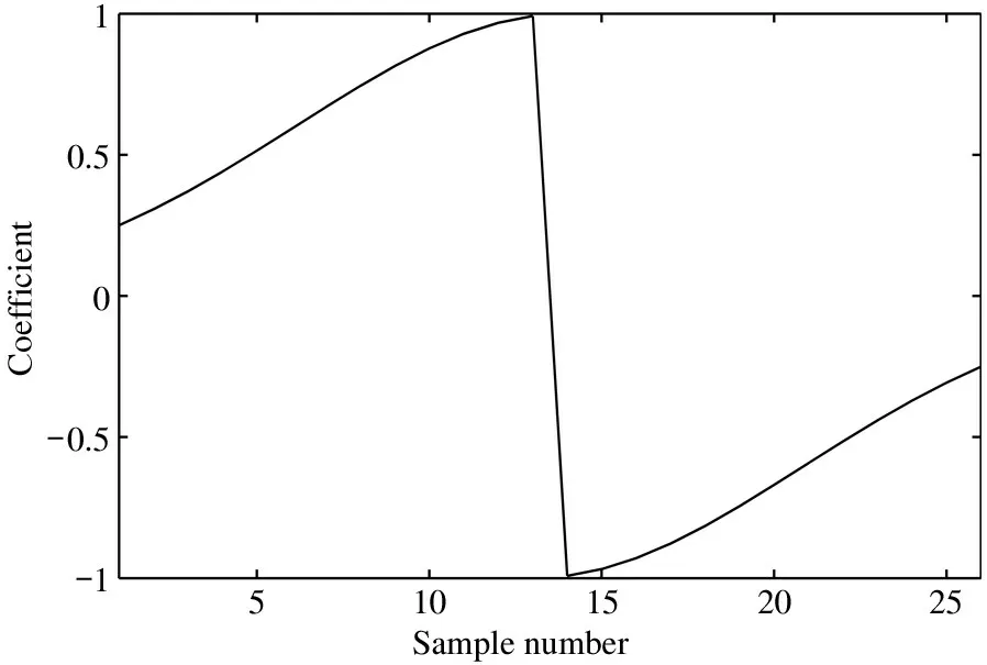
Fig.12 Optimal Gaussian weighting coefficient
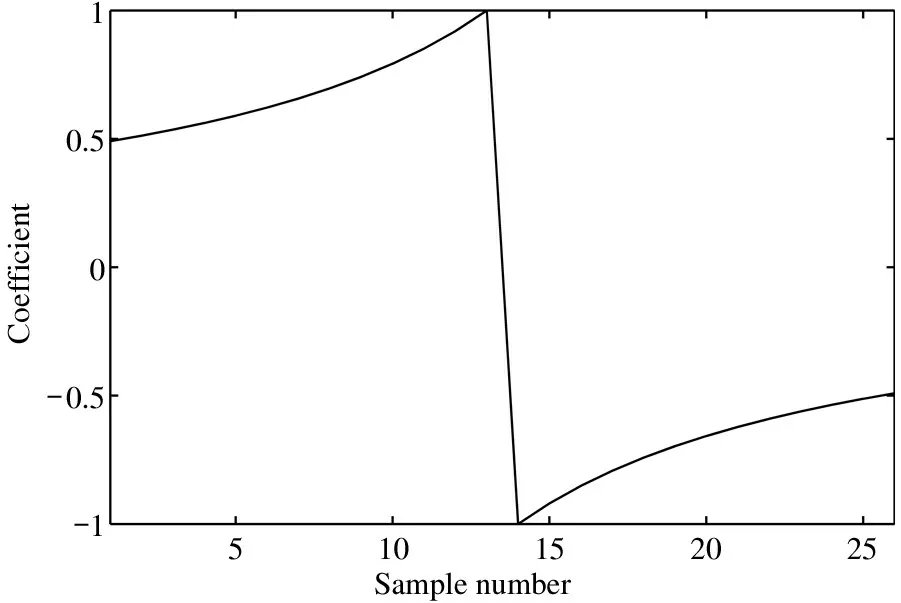
Fig.13 Optimal hyperbolic weighting coefficient

Fig.14 Optimal filter coefficient
(4)Obtain the image.Based on the calculated pixel information,the gray value of the image is obtained through gray calculation,and the image is saved as a RAW format image.Fig.15 shows the image in the test mode that was obtained by using the optimal filter,and Fig.16 shows the image in the normal imaging mode obtained by the optimal filter.
Fig.15 RAW format image
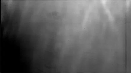
Fig.16 Image in normal imaging mode(using optimal filter)
Finally,the image can be obtained.Because the filter will attenuate the signal to a certain extent,the mean value of the image is inconsistent.Therefore,the coefficient of attenuation of the filter is set to ensure that the average value of the image obtained is consistent,and then the standard deviation of the filter is compared to evaluate the denoising performance of the filter.The experiment results for 1 MHz and 500 kHz readout rates are shown in Table 2 and Table 3.
According to Table 2 and Table 3,the followings are obtained.
(1)Compared with the traditional readout technology,the CCD detector digital readout technology has great advantages.On the one hand,ACDS circuit is removed and noise is suppressed.On the other hand,owing to the digital filtering process performed at the last end of the readout system,it has a certain ability to suppress other noises of the readout system.
(2)It can be seen from the mean value of the image before filter compensation that the differential mean filter and the hyperbolic coefficient weighting filter have a greater influence on the signal.The main reasonis that the weight of the filter coefficient is larger,which causes a larger attenuation,whereas the Gaussian coefficient weighted filter and optimal filter have less influence on the signal and better stability.

Table 2 Comparison result of traditional readout technology and digital denoising technology at 1 MHz readout rate

Table 3 Comparison result of traditional readout technology and digital denoising technology at 500 kHz readout rate
(3)According to the experiment results,as the CCD signal readout rate decreases,the noise becomes smaller.Among various filters,as the readout rate becomes smaller,the differential mean filter reduces its noise reduction performance.The main reason is that the differential mean filter has a weaker ability to suppress correlated noise.Contrariwise the filter based on the coefficient kernel distribution has a stronger ability to suppress correlated noise.
(4)By analyzing the standard deviation of the image after filter compensation,it can be seen that the optimal filter has better noise reduction performance at different readout rates.Especially,at 1MHz readout rate,the designed optimal filter has 60%,40%,32%,and 22%improvement in denoising performance compared with the traditional ACDS,differential mean filter,Gaussian coefficient weighting,and hyperbolic coefficient weighting,respectively.
5 Conclusions
According to the experiments and research in this article,the following conclusions are drawn.
(1)The digitized readout technology of the CCD detector is helpful to further reduce the noise of the readout system of a detector.It mainly relies on the oversampling technology of the high-speed A/D converter to obtain a large amount of data information,which is conducive to further optimization processing.
(2)Filters designed based on noise correlation,including Gaussian coefficient weighting and hyperbolic coefficient weighting,have greater denoise advantages than the differential mean filtering.
(3)Different digital filters cause different attenuation of the signal.Among them,Gaussian coefficient weighted filtering and optimal coefficient weighted filtering cause less loss to the signal and have better stability.
(4)The noise range and composition of CCD signal,for different readout rates,are different,and the denoising performance of the filter is different for different types of noise.The results show that in various filters,the optimal filter has the best denoising performance for different readout rates and different noises.
This technology can achieve the optimal suppression of camera system noise and effectively improve the detection capability of space targets or debris.In the future,optimal filter will be transplanted to FPGA to achieve pixel-level and real-time processing,thereby applying more widely.
 High Technology Letters2021年4期
- High Technology Letters的其它文章
- On the performance of full-duplex non-orthonogal multiple access with energy harvesting over Nakagami-m fading channels①
- Research on optimization of virtual machine memory access based on NUMA architecture①
- Online prediction of EEG based on KRLST algorithm①
- Reconfigurable implementation ARP based on depth threshold in 3D-HEVC①
- Positive unlabeled named entity recognition with multi-granularity linguistic information①
- Behavior recognition algorithm based on the improved R3D and LSTM network fusion①