
Application of local Monte Carlo method in neutronics calculation of EAST radial neutron camera
2022-03-10 03:50LiangshengHUANG黄良胜LiqunHU胡立群LuyingNIU牛璐莹MengjieZHOU周梦洁BingHONG洪兵KaiLI李凯RuixueZHANG张瑞雪andGuoqiangZHONG钟国强
Plasma Science and Technology 2022年2期
Liangsheng HUANG(黄良胜),Liqun HU(胡立群),Luying NIU(牛璐莹),Mengjie ZHOU(周梦洁),Bing HONG(洪兵),Kai LI(李凯),Ruixue ZHANG(张瑞雪) and Guoqiang ZHONG(钟国强)
1 Institute of Plasma Physics,Hefei Institutes of Physical Science,Chinese Academy of Sciences,Hefei 230031,People’s Republic of China
2 University of Science and Technology of China,Hefei 230026,People’s Republic of China
3 Sichuan Engineering Laboratory for Nuclear Facilities Decommissioning and Radwaste Management,Nuclear Power Institute of China,Chengdu 610005,People’s Republic of China
Abstract The Local Monte Carlo(LMC)method is used to solve the problems of deep penetration and long time in the neutronics calculation of the radial neutron camera(RNC)diagnostic system on the experimental advanced superconducting tokamak(EAST),and the radiation distribution of the RNC and the neutron flux at the detector positions of each channel are obtained.Compared with the results calculated by the global variance reduction method,it is shown that the LMC calculation is reliable within the reasonable error range.The calculation process of LMC is analyzed in detail,and the transport process of radiation particles is simulated in two steps.In the first step,an integrated neutronics model considering the complex window environment and a neutron source model based on EAST plasma shape are used to support the calculation.The particle information on the equivalent surface is analyzed to evaluate the rationality of settings of equivalent surface source and boundary.Based on the characteristic that only a local geometric model is needed in the second step,it is shown that the LMC is an advantageous calculation method for the nuclear shielding design of tokamak diagnostic systems.
Keywords:equivalent surface source,radial neutron camera,EAST,local Monte Carlo method
1.Introduction
The radial neutron camera(RNC)on the experimental advanced superconducting tokamak(EAST)device mainly measures the uncollided neutrons in the plasma region of the upper polar to obtain the spatial distribution of plasma neutrons[1].The camera consists of six liquid scintillation detectors BC-501A,a two-stage shielding collimator,six sight-line holes and a support frame,and is installed in the equatorial window K,as shown in figure 1.The collimator is composed of polyethylene(containing 5% boric acid),lead plate and stainless steel(reinforced structure),with a total weight of approximately 5 tons.The RNC(Φ5 cm)and the radial gamma camera(Φ3 cm)share a set of collimators.The preliminary design of RNC was completed by Zhong[2].In order to evaluate the shielding performance of the collimator and calculate the neutron flux at the six detector positions of the RNC,it is necessary to perform a three-dimensional neutron and photon coupled transport analysis on the RNC.
The calculation of particle transport for the geometry of figure 1 is difficult because it is both a deep penetration problem and a long time transport problem.First,the RNC is far away from the plasma core,especially the detector position is about 550 cm away from the core;second,the aperture of the collimating shield(Φ5 cm)is small and the collimation length is long(85 cm),so it is difficult for the uncollided neutron to be transport to the detector;third,the shielding layer of the RNC is nearly 1 m(70 cm polyethylene and 30 cm lead),and the interaction area of the structure by direct neutrons or primary scattered neutrons is small(the lengthwidth ratio is 2.8:1).Under the computing resources of 56 CPUs running continuously for 7 d,the local variance reduction method based on the weight window generation[3,4]and the global variance reduction(GVR)method[5]based on flux were used to perform neutron analysis on figure 1.The relative error of the result is greater than 0.1.Otherwise,multiple computing resources are required to obtain reliable results.
In view of the above-mentioned transport problem and limited computing resource,this work used the Local Monte Carlo(LMC)method to simulate the transport process of radiation particles(neutrons and photons)in two steps to obtain the radiation distribution of the RNC and the neutron flux on each channel detector.The LMC method can solve some difficult problems within reasonable error allowable range.This method has been applied and verified on the International Fusion Materials Irradiation Facility[6]and the International Thermonuclear Experimental Reactor[7-9]for nuclear analysis of the device.The subsequent contents are as follows:section 2 describes the establishment of the integrated neutronics model and the calculation method of LMC,section 3 presents the analysis and discussion of the results of different calculation stages of the LMC,section 4 is the conclusions.
2.Computational methodology
2.1.Integration of neutronics models
Due to the limited window resources of the EAST device and the weight of the RNC,the RNC camera shares the window K with multiple diagnostic systems.Considering the influence of window on the calculation,the main diagnostic components of window K are modeled in detail.Since the shielding material at the back end of RNC is thin,the scattering effect of concrete shielding wall is considered in this work.In order to facilitate the calculation of radiation transport,the CAD diagrams of RNC structure and window are properly simplified.MCAM(Monte Carlo Automatic Modeling system)software[10]is used to transform the CAD model into the neutronics model,and it is integrated into the 1/8 sector EAST neutronics model[11](basic model).The integrated neutronics model is shown in figure 2.
2.2.LMC method
In order to solve the particle transport problem of the above integrated model,the LMC method is applied.This method uses surface source write and surface source read files[3]to carry out neutron and photon coupling transport calculation in two steps,so as to obtain the radiation of RNC and the neutron flux on each channel detector.The calculation process of LMC is shown in figure 3.The plasma neutron source is calculated by the neutron source model based on EAST plasma shape.The source selects classic shot #77160 of the EAST deuterium plasma discharge,for more details see the[12].
Step-by-step calculation is the same as calculating fluid medium.First,the boundary conditions of a local area are obtained,and then various dynamic parameters of the area are calculated.It is difficult to simulate the transport of neutrons from the plasma core to the RNC detector.However,it is easy to first simulate the transport of neutrons from the plasma core to the outer surface of the RNC structure.Because of this process,the structure material has less absorption of neutrons(especially the direct part),and the surface area is larger(the target is larger).In the second step,the outer surface of the RNC structure is used as a surface source,which retains the information(position,emission angle,energy,weight,etc)of the particles passing through the surface in the first step.It is also easy to transport particles to the RNC model alone.Because the model is small,the calculation time is relatively short.These two processes indicate that the LMC method is suitable for the design of nuclear shielding structures of fusion reactor diagnostic systems or diagnostic windows in the future.In the initial stage of design,the shielding structure will be frequently modified due to various constraints.However,it takes a long time and expensive computing resources to use other variance reduction methods for transport calculations to obtain results that meet the accuracy.Fortunately,the modification of the shielding structure or window used for diagnosis has little effect on the calculation results of the first step of LMC(unless the plasma-facing structure is changed).Therefore,to evaluate whether the modified shielding structure meets the requirements each time,only the second step of calculation is required.This increase in computational efficiency is obvious and easy to see,and it can feed back the evaluation results in time.
It is undeniable that reasonable settings of surface sources and boundary conditions are very important to ensure the reliability of the results.The equivalent surfaces in the first step are shown in figure 4.In this work,the contribution of the bottom surface source(S6)to the detector count is ignored.The local 3D neutronics model calculated in the second step is shown in the red dashed box in figure 2(a),with only the RNC structure.The model does not set the boundary of the reflecting surface,and the particle graveyard is outside the wireframe.
3.Results and discussions
3.1.Equivalent surface source analysis
The setting of the equivalent surface source is the key to the LMC calculation.In the first step,the equivalent surface records information about the particle’s passing through the surface,including its position,angle,energy,weight,time,and whether or not a collision occurred.In the second step,the equivalent surface source is used as the particle source input for transport calculations.In order to reduce the size of the file for recording particle information,only particles that pass forward through(into the RNC structure)the equivalent surface are recorded,because particles leaving the RNC structure do not contribute to the second step.This paper analyzes the particle information on the equivalent surface source to evaluate the rationality of the setting of the equivalent surface source,as shown in figure 5.
It can be seen from figure 5 that the neutrons mainly enter the RNC structure from the surface S1.The composition of small angle incident is larger.The number of particles with an incident angle of 0-60 degrees accounts for 99%,and with energy greater than 1.5 MeV accounted for about 10.5%.It is shown that these neutrons mainly come from the scattering of the window K,followed by the direct neutrons generated in the plasma region.The distribution of neutrons on S1is as follows:
• There are more neutrons in the upper half than in the lower half.This is reasonable according to the fact that the plasma neutron source is mainly concentrated in the core and the line of sight in figure 2(b).
• The small number of particles in the upper right corner may be caused by the shielding of neutrons by other diagnostic components of the window K.
The neutrons entering the RNC from S3,S4and S5mainly come from the scattering of adjacent windows and the reflection from the reflecting surface,and a small amount comes from the scattering of the shielding wall.The proportions of particles with energy greater than 1.5 MeV on S3,S4and S5are 2.5%,10.3%and 5.1%,respectively,indicating that there are relatively more neutrons reflected from the reflecting surface on S4.There is also the case of uneven particle distribution,and the number of particles close to the surface S1is more.
The neutrons on S2come from the scattering of the shielding wall,and the distribution is relatively uniform.Particles with energy greater than 1.5 MeV account for 2.3%,and these components come from the backscatter of the shielding wall.
The photon current distribution on each equivalent surface source is similar to that of neutron.Because the photons are secondary particles produced by the interaction between neutrons and matter,they have a certain correlation,as shown in figure 6.The change in slope may be caused by the interaction between neutrons and different materials.High energy(E>1 MeV)photons induced by neutrons may interfere with the measurement of runaway electrons.
3.2.Radiation distribution of RNC
The particle source input in the second step is the particles recorded by the equivalent source in the first step(neutrons and photons induced by neutrons).They retain the information of the plasma neutron source,the scattering of particles by the materials around the RNC,and the generation of secondary particles(photons).Therefore,in the second step,only the local neutronics model of the RNC geometry is needed,and the interaction between particles and other structures is not considered again.Because of this characteristic,the complexity of the model is greatly reduced,which is beneficial to improve the calculation efficiency.At the same time,there is a problem that the result of the point detector count is low,ignoring the contribution of the particles to the count in the first step.Therefore,the track length counts are used in the second step.In this step,only the flux distribution of the RNC structure behind the surface source is reliable.
Figures 7 and 8 show the radiation distribution of the RNC from different perspectives.The collimator attenuates the neutron stream by 103times;the neutron stream enters the detector region mainly along the collimated light,and also enters through the aperture of the RNC backplane.The crosstalk between the upper and lower channels is very small.The photons induced by neutrons are attenuated by a factor of 103.There is no lead material for shielding in the bottom area of the inner space of the first-stage collimator,which results in a high photon flux,but has little effect on the counts of channels#5 and#6.Analysis shows that the front end of the two-stage collimator has a good shielding performance,but the back end needs more shielding.
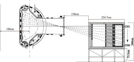
Figure 1.RNC structure diagram.

Figure 2.The integrated neutronics model.(a) Z=219.9 cm plane view,the red dotted line is the local 3D neutronics model used for the second step,S1,S2,S4,and S5 are the equivalent surface sources on each side,and S3 is the upper plane.(b)A vertical section view along the line AA′ in(a),and showing six lines of sight.
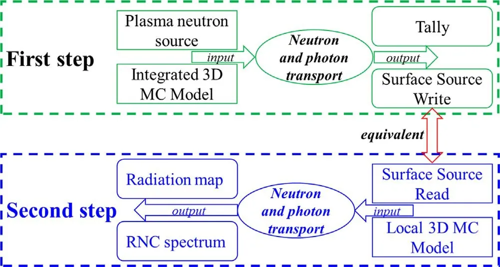
Figure 3.The calculation process of LMC.
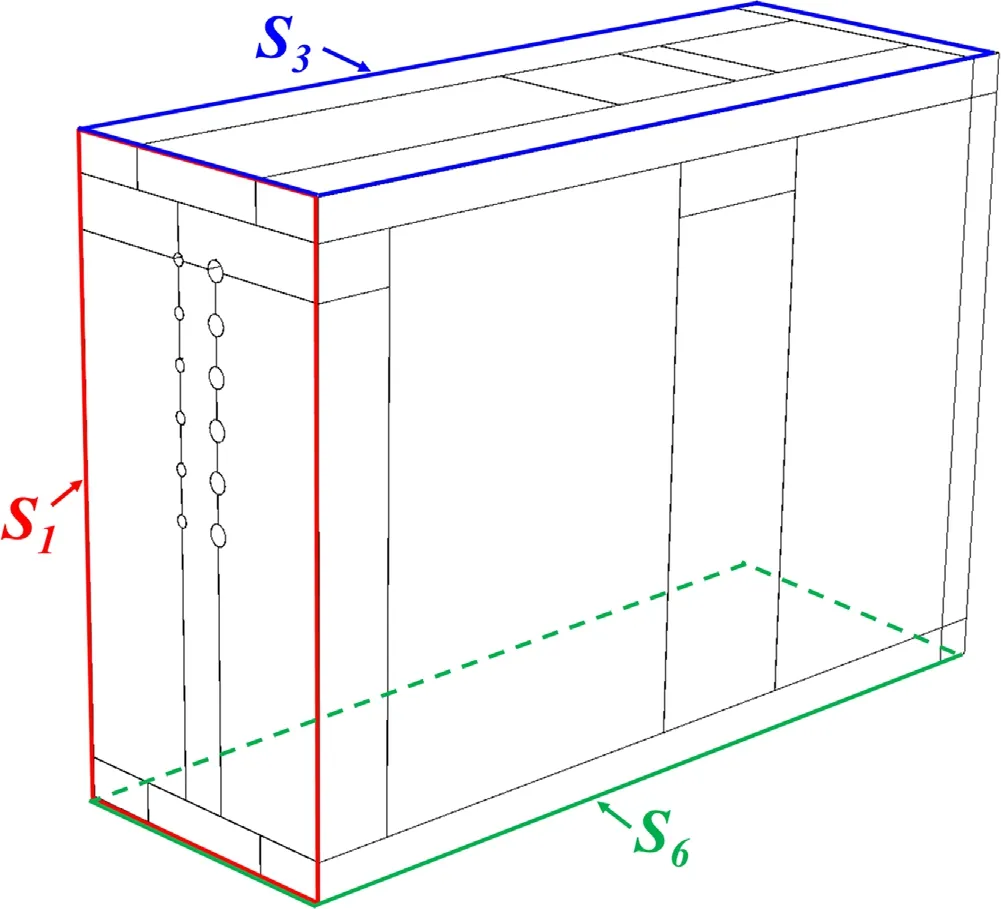
Figure 4.Set the six surfaces of the RNC boundary as equivalent surface(record particle information in the first step,and generate particle as a surface source in the second step).The positions of S2,S4 and S5 can be seen in figure 2(a).
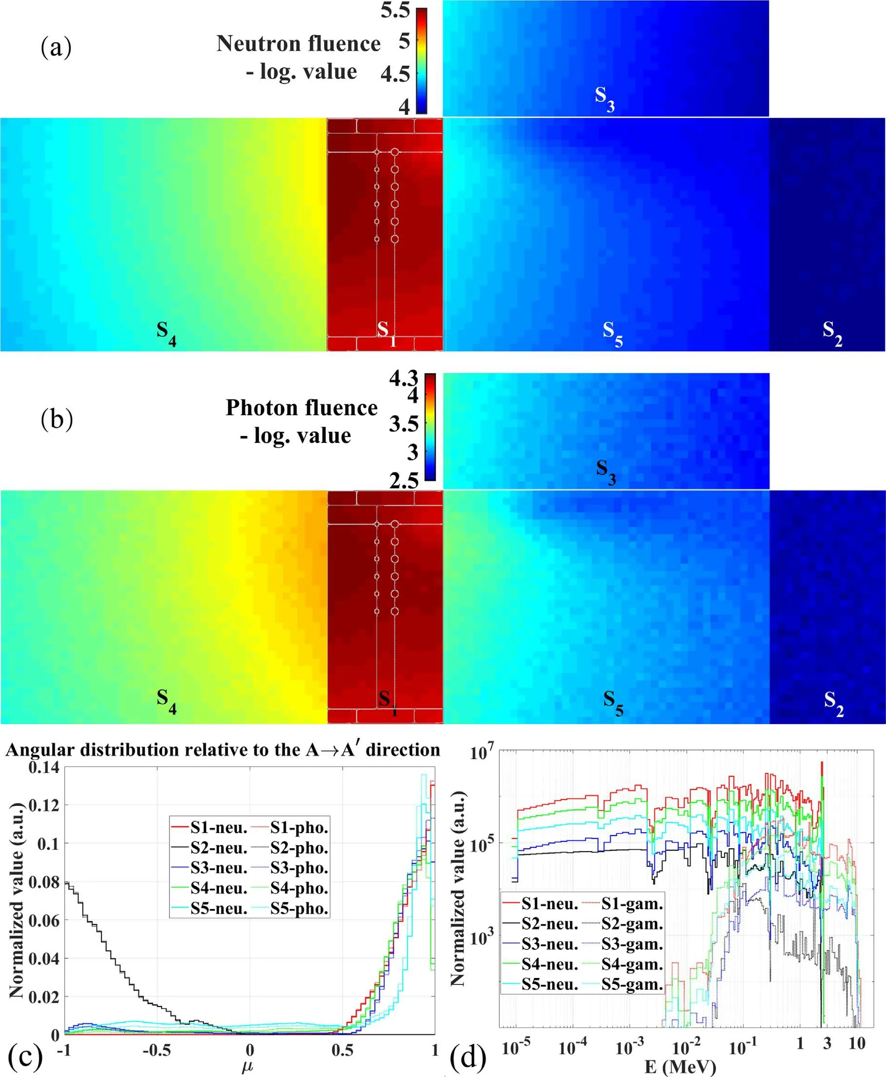
Figure 5.Particle information on the equivalent surface source.(a)Neutron current distribution,(b)photon current distribution,(c)statistics of particle angular distribution on the entire surface,where μ is the cosine value of the angle between the direction of particle’s movement and (d)statistics of particle energy on the entire surface.
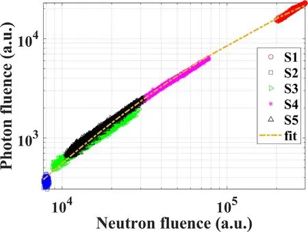
Figure 6.The statistics of neutron current and photon current of each grid on each equivalent surface.
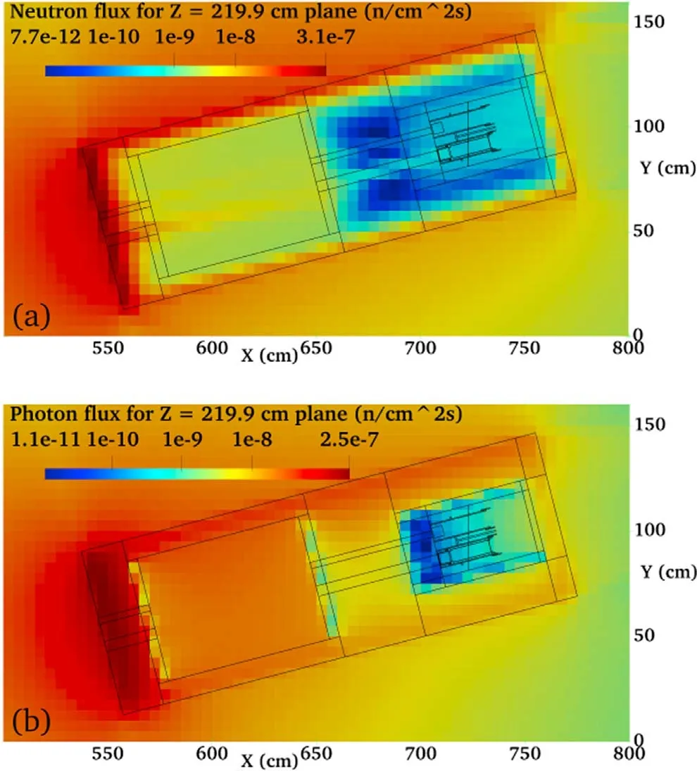
Figure 7.RNC radiation distribution in the horizontal direction(Z=219.9 cm plane of parallel channel #1 line of sight).(a)Neutron flux distribution,(b)photon flux distribution.
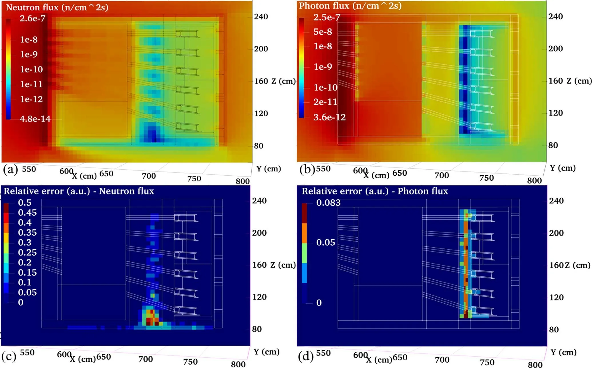
Figure 8.RNC radiation distribution in the vertical direction.(a)Neutron flux distribution,(b)photon flux distritbution,(c)the relative error of neutron flux in(a),(d)the relative error of photon flux in(b).
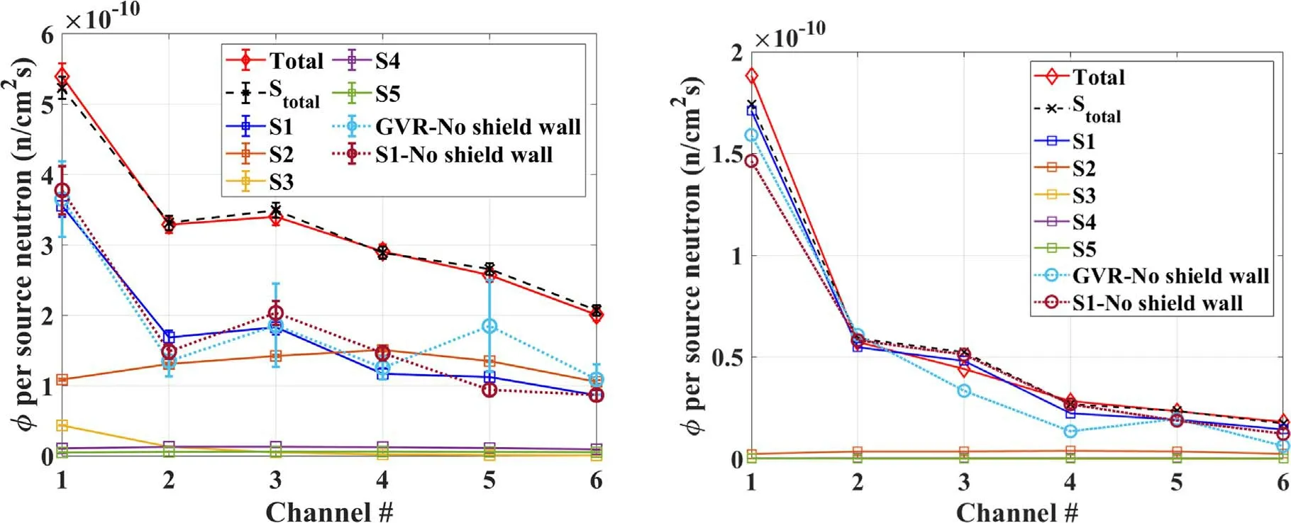
Figure 9.Neutron flux at each detector of RNC.Left:no energy threshold is set.Right:1.5 MeV energy threshold is set.Note:‘No shield wall’means that there is no shield wall structure in the model of the first step,‘Stotal’is the sum of the calculated results of each equivalent surface source,‘Total’ is the calculated result of all equivalent surface sources in the second step as the source input.
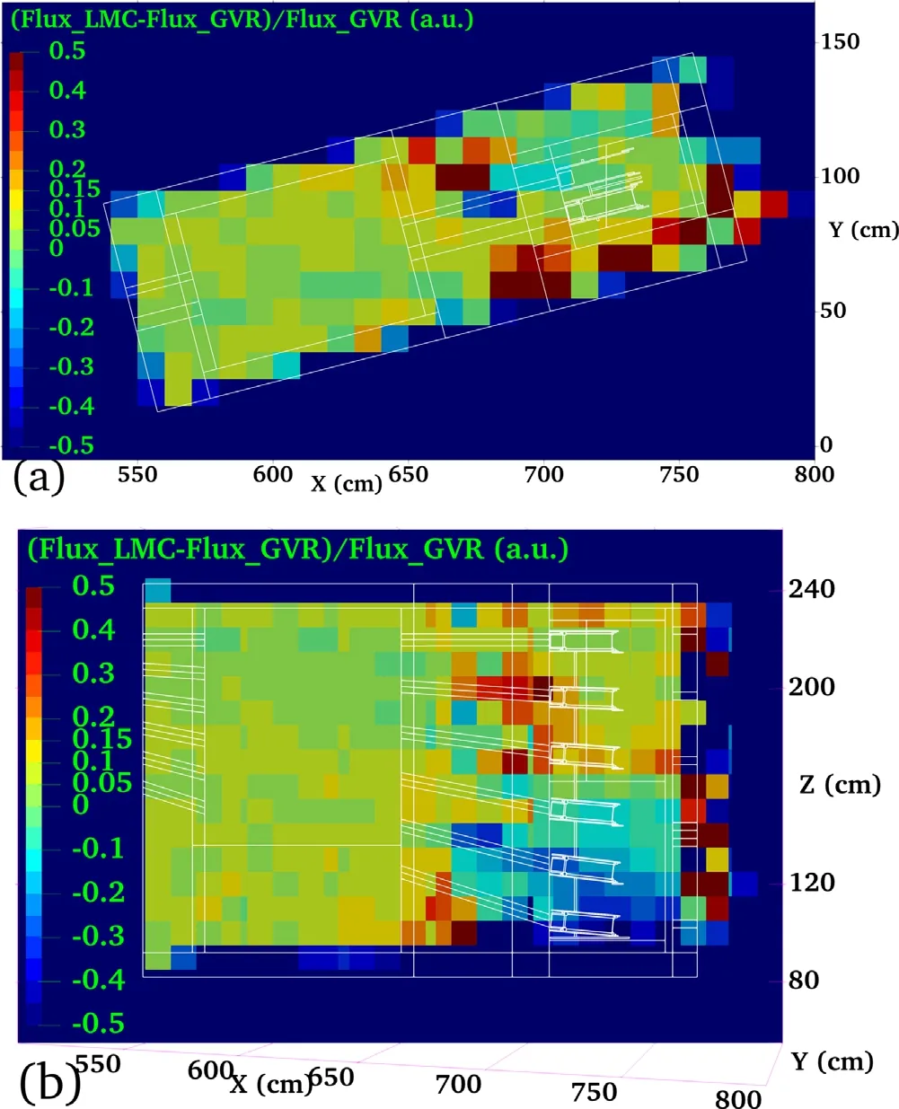
Figure 10.The deviation between the neutron flux distribution calculated by the LMC method and the GVR method.(a)Deviation in horizontal direction(Z=219.9 cm plane),(b)the deviation in the vertical direction.In order to highlight more the deviations between-0.2 and 0.2,we use this color for the legend of 0.45-0.5 indicating deviation values greater than or equal to 0.45;the same treatment is applied between -0.5 and -0.45.
3.3.Neutron flux at each detector
In the second step,considering a variety of cases,the neutron flux values at the six detector positions of the RNC are calculated,and compared with the flux values calculated by the GVR method without the shielding wall,as shown in figure 9.The change trend of LMC results is consistent with GVR results.At the same time,the relative error of the LMC result meets the requirements(<0.1).In addition,to have a more detailed comparison with GVR,we used the LMC method to calculate the case without a shielding wall in the first step,and the deviations between the neutron flux distributions calculated by the two methods are shown in figure 10.The deviation between the LMC results and the GVR results within the RNC geometry is basically controlled within±20%,which indicates that the LMC results have a high reliability.
Without setting the energy threshold,the neutrons entering from the surface S2make a great contribution to the flux of the detector.Therefore,the impact of the shielding wall should be considered when calculating the flux distribution of the diagnostic system.
In order to reduce the influence of scattered neutrons,the energy threshold of 1.5 MeV is set,and the neutron flux is reduced to 0.36-0.1 times of the original.If a shot of plasma discharge produces 1011neutrons,only a few neutrons enter the detector.Therefore,RNC is not suitable for low-power discharge experiments(neutron rate<1012n/shot)to measure fusion neutrons.
By setting the energy threshold,the contribution of the S2equivalent surface source to the flux at the RNC detector is very small,and the impact of the shielding wall can be basically ignored.Therefore,the EAST neutronics model of a sector can be applied to the transport calculation of RNC detectors that set the energy threshold.
4.Conclusions
Aiming at the problems of deep penetration and long time in the transport calculation of the RNC,the LMC method is used to calculate the radiation distribution of RNC and the flux on each detector.The transport analysis of the RNC using the LMC method shows that the collimator has good shielding performance,but more shielding is required at the backplane.RNC is suitable for discharge experiments under high neutron rate.According to the requirements of actual calculations,determine whether it is necessary to consider the influence of shielding wall on the results.Compared with the neutron flux in each channel calculated by the GVR method without the shielding wall,the change trends of the two are consistent,which is within the reasonable error range,it is shown that the LMC calculation is reliable.
In addition,the LMC calculation process is analyzed in detail,and the transport process of radiation particles is simulated in two steps.In this paper,the computer times of each stage of LMC and GVR are listed separately,as shown in table 1.It can be seen that the LMC method(two-step cumulative computation time)has no significant advantage of reducing the computation time compared to the GVR method.However,the calculation time of the second step of LMC is about 10%of the first step,which basically corresponds to the material volume of the neutronics model.Therefore,it can be shown that the LMC method is an advantageous calculation method suitable for the design of nuclear shielding structures of fusion reactor diagnostic systems or windows in the future.
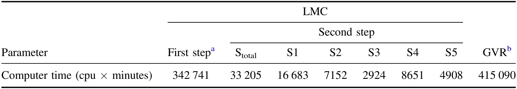
Table 1.The computer times for each stage of LMC and GVR.
Subsequently,we will verify and develop the LMC method to be more suitable for nuclear shielding analysis for future fusion reactor diagnostic systems.
Acknowledgments
The authors would like to thank members of EAST experimental team for their support and help in this research.This work was supported by Users with Excellence Program of Hefei Science Center CAS(No.2020HSC-UE012),Comprehensive Research Facility for Fusion Technology Program of China(No.2018-000052-73-01-001228),and National Natural Science Foundation of China(No.11605241).
ORCID iDs
猜你喜欢
火花(2022年4期)2022-06-16
音乐天地(音乐创作版)(2022年2期)2022-05-12
青年文学家(2021年29期)2021-11-19
廉政瞭望·下半月(2021年1期)2021-05-17
晚晴(2021年1期)2021-05-17
金桥(2021年2期)2021-03-19
课堂内外·好老师(2020年11期)2020-12-14
青年生活(2020年5期)2020-03-27
现代家庭(2017年3期)2017-03-15
故事会(2015年9期)2015-05-14
 Plasma Science and Technology2022年2期
- Plasma Science and Technology的其它文章
- Investigation of short-channel design on performance optimization effect of Hall thruster with large height-radius ratio
- Multi-layer structure formation of relativistic electron beams in plasmas
- Mode structure symmetry breaking of reversed shear Alfvén eigenmodes and its impact on the generation of parallel velocity asymmetries in energetic particle distribution
- Interaction between energetic-ions and internal kink modes in a weak shear tokamak plasma
- Investigation of the compact torus plasma motion in the KTX-CTI device based on circuit analyses
- Anomalous transport driven by ion temperature gradient instability in an anisotropic deuterium-tritium plasma