
Numerical study of the effect of coflow argon jet on a laminar argon thermal plasma jet
2022-06-01 07:56XuZHOU周旭XianhuiCHEN陈仙辉TaohongYE叶桃红MinmingZHU朱旻明andWeidongXIA夏维东
Plasma Science and Technology 2022年5期
关键词:桃红
Xu ZHOU (周旭), Xianhui CHEN (陈仙辉), Taohong YE (叶桃红),Minming ZHU (朱旻明) and Weidong XIA (夏维东)
School of Engineering Science, University of Science and Technology of China, Hefei 230022, People’s Republic of China
Abstract The effects of the velocity and width in coflow argon jet inlet on the flow characteristics of laminar argon thermal plasma jet flowing into the cold air have been studied by the large eddy simulation methods.The Kelvin-Helmholtz instability between argon thermal plasma jet and coflow argon jet causes the transition from a laminar jet to a turbulent jet in the presence of coflow argon jet.Moreover, increasing the velocity and width in coflow argon jet inlet can enhance turbulent transport and provoke coherent structure in the downstream of thermal plasma jet.And the mixing characteristics between argon thermal plasma,coflow argon and ambient air are strengthened.In addition, the width in coflow argon jet inlet has a significant effect on the distribution of temperature in the upstream of thermal plasma jet.It was also found that the transition occurs in advance with the increase of velocity and width in coflow argon jet inlet.
Keywords: thermal plasma jet, coflow argon jet, transition, mixing characteristics, large eddy simulation
1.Introduction
The various flow configurations of thermal plasma, including free jets [1-3], coflow jets, transverse jets [4-6] and counter flows [7-9], etc, have been widely used in industrial applications.As one of the basic flow configurations, thermal plasma jets integrated with coflow argon jets have been widely used in welding,cutting,spraying and material preparation,and so on.
In atmosphere plasma spraying,solid particles are heated and melted by the thermal plasma jets with sufficiently high temperature and velocity, which then splash on the substrate in order to form the coatings with special physical and chemical properties [10].However, the thermal plasma jets will be rapidly decelerated and quenched due to the large amount of entrained cold ambient air into jets,which seriously affects the properties of the coatings,such as porosity,thickness and oxide contents, and even leads to the failure of coatings[11-14].Generally, coflow argon jets are adopted at the end of the nozzle of the plasma torch to decrease the entrainment of cold air into thermal plasma jets.Furthermore, coflow argon contributes to creating an inert gas atmosphere, and avoids the interaction between solid particles with high temperature and ambient air [15-21].
In the process of thermal plasma arc welding and cutting,coflow argon jets cannot only inhibit the air oxidation of materials,but also protect the nozzle of the thermal plasma torch from molten materials splashed from the work-piece.Coflow argon jets also provide a cold boundary layer around the anode wall, which reduces the heat carried away by cooling water.In addition,coflow argon jets squeeze the arc column and raise the core temperature of thermal plasma jet, which contribute to improving the power density of thermal plasma [22-24].
Recently, thermal plasma jets integrated with coflow argon jets have shown a unique advantage of superfast production graphene[25].The graphene prepared by this method shows few basal defect and presents high quality.The entire exfoliation process includes three parts: thermal shock of graphite from thermal plasma, and two-stage shearing in the laminar and turbulent region of thermal plasma jets.The experimental results also show that the flow rate of coflow argon jets have a significant influence on the temperature,velocity and exfoliation efficiency of graphite.
Many experimental and numerical studies of the momentum, mass and heat transfer characteristics of thermal plasma free jets have been implemented [1-3, 26-29].Although thermal plasma jets integrated with coflow argon jets have been widely used in industrial applications, the interactions between coflow argon jets and thermal plasma jets are unclear.Kim et al [17] found that the coflow argon jets with high velocity are conducive to obtaining a thick coating with low porosity and oxide contents.Experimental studies were carried out to investigate the effects of different coflow nozzle configurations on the electro-thermal efficiency of plasma torch [18].A small number of numerical simulations were performed to investigate the effect of coflow argon jets on the content of cold air into thermal plasma jets.Twodimensional numerical simulation results show that coflow argon jets can effectively reduce air entrainment into the turbulent plasma jets,but have no significant influence on the distribution of temperature and velocity in the thermal plasma jets[16].Cheng et al[19]found that the velocity and width in coflow argon jet inlet have significant impacts on the ambient air content in the laminar thermal plasma jets.
Most of experiment studies focused on the properties of materials obtained by the thermal plasma jets integrated with coflow argon jets.However, the flow characteristics of laminar thermal plasma jets integrated with coflow argon jets are unclear due to the limitation of experimental diagnostic methods,and the properties of materials are closely related to the flow characteristics of thermal plasma jets.On the other hand, numerical studies have been used to reveal the flow mechanisms of thermal plasma jets due to the improvement of computational performance.The steady-state assumptions,two-dimensional axisymmetric computational domain, and standardk-εturbulence model are adopted in most numerical simulations [15, 16, 19, 30].But the standardk-εturbulence model is only applicable for the turbulent flows with high Reynolds numbers.In addition, only mean flow field can be provided, and the turbulent fluctuation of thermal plasma jets cannot be resolved under these assumptions.Large eddy simulations can provide more fundamental flow information and have been popular tools to study thermal plasma jets[31-35].In this study,a numerical code solving argon thermal plasma jets flowing into ambient cold air was embedded based on OpenFOAM [36], and the influences of velocity and width in the coflow argon jet inlet on the flow characteristics of laminar argon thermal plasma jets were investigated with threedimensional large eddy simulation methods.
2.Numerical methods
2.1.Geometry and case setting
As shown in figure 1,the diameter of thermal plasma jet inlet(marked in red in figure 1) is D = 8 mm.The coflow argon jet inlet (marked in yellow in figure 1) is adjacent to the thermal plasma jet inlet, and the width in coflow argon jet inletWcois variable for different cases.In addition, the outer diameter of plasma torch isDout=8.75D.
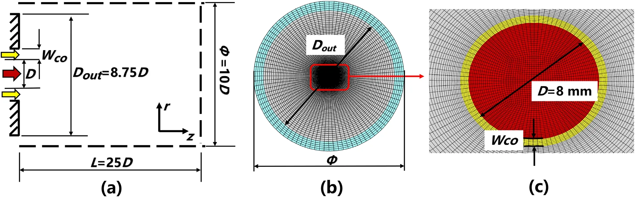
Figure 1.Schematic diagram of the physical model and computational domain.
In this paper,the laminar argon thermal plasma jet flowing into the ambient air is used as a base case 1.Table 1 shows the detailed parameters of laminar thermal plasma jet.The maximum velocityUjand maximum temperatureTjin the laminar thermal plasma jet inlet are 600 m s-1and 13 000 K, respectively.The configurations of coflow argon jet are considered to reveal the effect of coflow argon jet in the cases 2-4.The detailed parameters of coflow argon jet are shown in table 2.Where,the bulk velocities in coflow argon jet inletUcoare 20 m s-1and 50 m s-1, respectively, and the widths in coflow argon jet inletWcoare 0.5 mm and 1.16 mm, respectively.The effects of velocity in coflow argon jet inle are studied by case 2 and case 3,and the effects of width in coflow argon jet inle are studied by case 2 and case 4.It is worth noting that the parameters of thermal plasma jet in the cases 2-4 are the same as base case 1.
2.2.Numerical methods
In our previous work [37], the numerical codes have been embedded and validated to solve argon thermal plasma jet flowing into the cold argon based on the OpenFOAM [36].The following assumptions are made: (i) the plasma is in the LTE (Local Thermodynamic Equilibrium) and LCE (Local Chemical Equilibrium)state;(ii)the plasma is assumed to be optically thin,so the radiative heat loss is modeled as a source term dependent on the component and temperature of plasma;and (iii) the buoyancy effects are negligible because of their smallness.Based on the foregoing assumptions, the filtered large eddy simulation compressible governing equations are
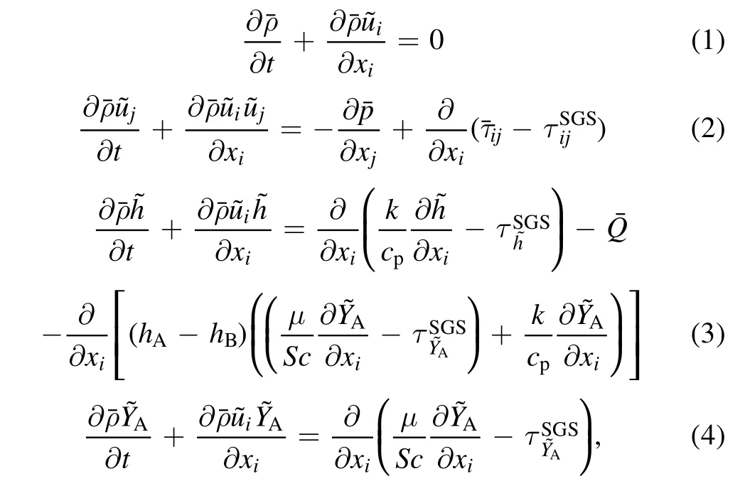
where, superscript ‘~’ represents Favre-filtered operation,and ‘-’ represents spatially-filtered operation for large eddy simulation.t,andare time, spatial coordinate component, velocity component, pressure and mass fraction of argon in the argon-air mixture,respectively.The filtered viscous stressis defined based on the eddy viscosity hypothesis as

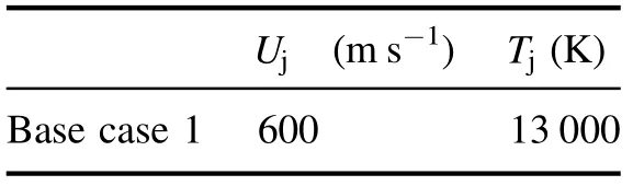
Table 1.Inflow conditions of the laminar thermal plasma jet.

Table 2.Case settings of large eddy simulation.

Figure 2.The relationships between density, dynamic viscosity,specific heat, specific enthalpy and temperature under different argon mass fractions.
In the governing equations (2)-(4), the sub-grid scale terms denoted by superscript ‘SGS’ are closed by the Smagorinsky model [39].The sub-grid stress terminequation (2) reads
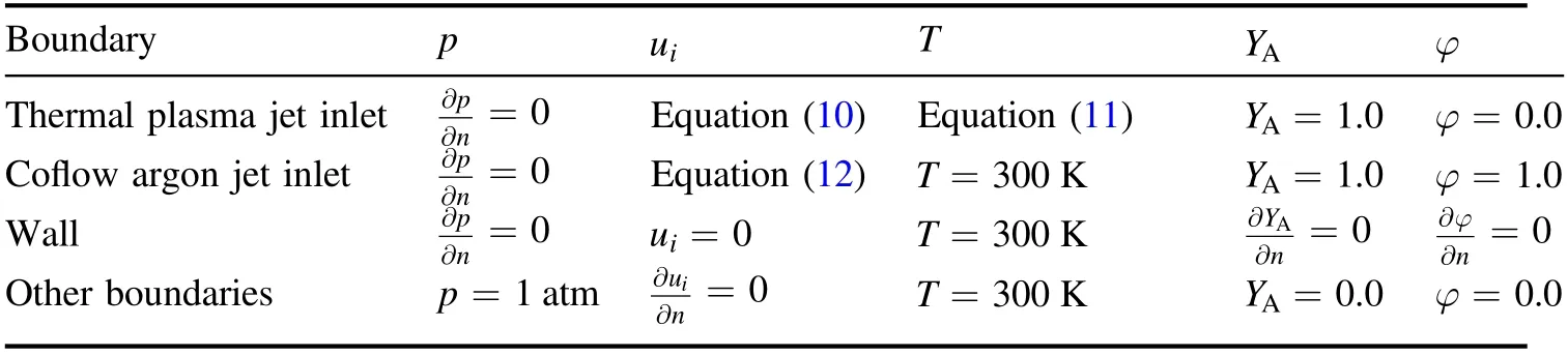
Table 3.Boundary conditions of numerical simulation.
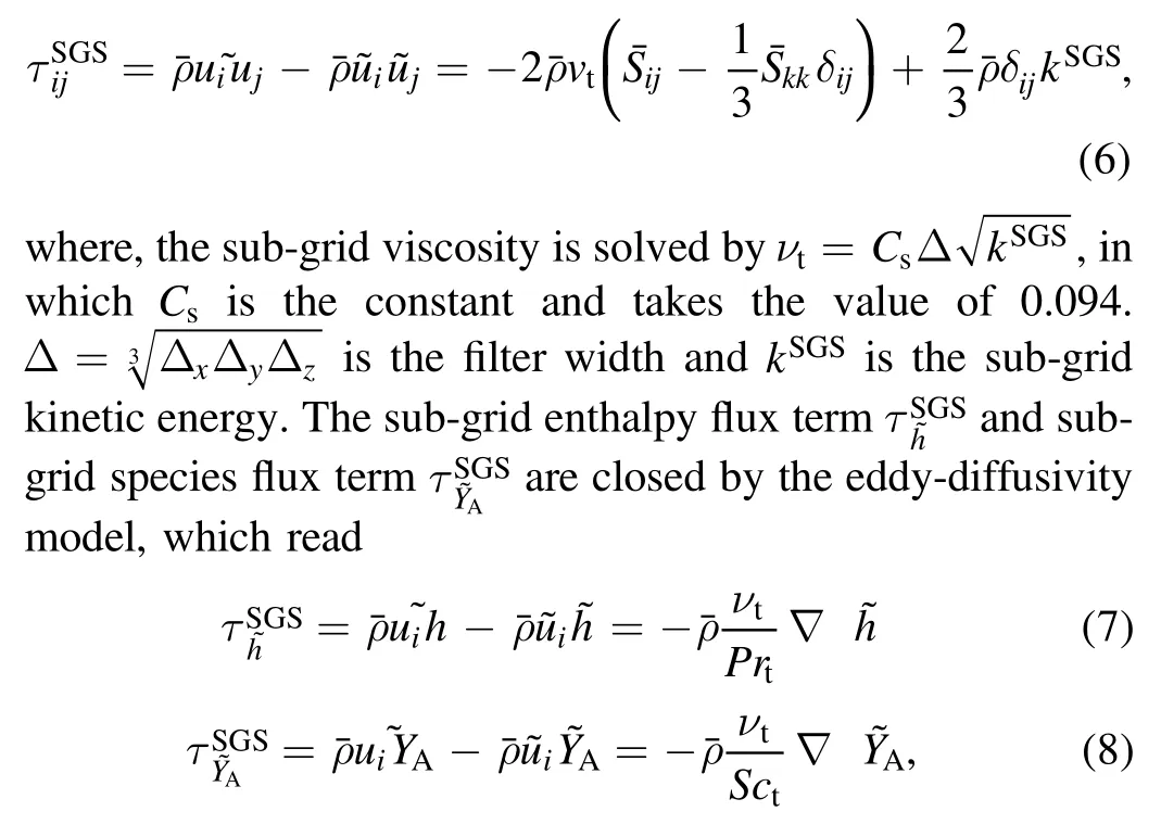
where, the turbulent Prandtl numberPrtand Schmidt numberSctare set as 0.9 and 1.0,respectively[3].The last term on the right side of the energy conservation equation (3) represents energy transport caused by species diffusion [40].hAandhBare the specific enthalpy of pure argon and pure air respectively, which depend only on temperature.In order to distinguish the distribution of argon in the thermal plasma jet and coflow argon jet, the passive scalarφis added to represent only the mass fraction of argon in the coflow argon jet, and the conservation equation is as follows:

where, the sub-grid scalar flux termIn particular,the passive scalarφhas no effect on the distribution of other physical quantities.
Figure 1 shows the computational domain and grid employed in the simulations.Computing domains are 25D×5D×2π in size and divided into 350×99×96 hexahedral structured grids.The total number of hexahedral grids are about 3.5 million.Moreover,the minimum grids can be found in the jet inlet and shear layer, and the size is 0.08 mm.
Table 3 shows the boundary conditions employed in this study.The inflow conditions of velocity and temperature in the argon thermal plasma jet inlet satisfy the following distributions [1, 3, 27]


where, the jet radius isRin= 4 mm,the wall temperature isTw= 300 K,and the fitting parameternUandnTare 1.4 and 2.3, respectively.The inflow conditions of velocity in the coflow argon jet inlet satisfy the 1/7 power distribution[41, 42]
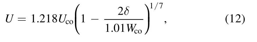
where,δis the radial length from the center of coflow argon jet inlet.2%turbulence intensities are employed in the inflow conditions of velocity and the temperature is 300 K, respectively.The mass fraction of argon is set asYA= 1.0in the jet inlet of thermal plasma and coflow argon, and the passive scalar is set asφ=1.0in the coflow argon jet inlet.No-slip walls are set on the inner wall of the plasma torch.The open boundary conditions are employed in the other faces to allow fluid to enter and exit freely.The temperature and pressure of cold air areT∞=300 K andP∞=1 atm,respectively.In addition, the information on numerical validations can be found in our previous work [37].
3.Results and discussion
3.1.Mean flow field
Figures 3-6 show the spatial distributions of mean axial velocity,mean temperature,mean argon thermal plasma mass fraction and mean passive scalar for cases 1-4.It can be seen that the effects of velocity and width in the coflow argon jet inlet on the mean flow field are obvious in comparison to base case 1.With increasing velocity and width in the coflow argon jet inlet,the length of argon thermal plasma jet or high temperature region reduces gradually, and the gradient of velocity and temperature enhance obviously.The thermal plasma jet has changed from a long laminar jet dominated by the molecular transport mechanism to a turbulent jet dominated by the turbulent transport mechanism, and the entrainment rate of the coflow argon and ambient air into the thermal plasma jet is significantly improved.For the case 3 and case 4 with the same mass flow in the coflow argon jet inlet, the effect of increasing velocity of coflow argon jet inlet on the mean flow field is far greater than that of increasing width of coflow argon jet inlet.It is worth noting that the lengths of regions in which the temperature surpasses 6000 K in case 2 and case 4 are slightly longer than those of case 1.Obviously,more coflow argon rather than cold air is entrained into upstream of thermal plasma jet due to the presence of coflow argon jet.On the other hand,the specific enthalpy and specific heat of argon are much lower than those of air at the same temperature, which causes the higher temperature in the upstream of the case 2 and case 4.

Figure 3.Distributions of mean axial velocity for cases 1-4.The three black lines represent the contours with mean axial velocities of 100 m s-1, 300 m s-1 and 500 m s-1, respectively.
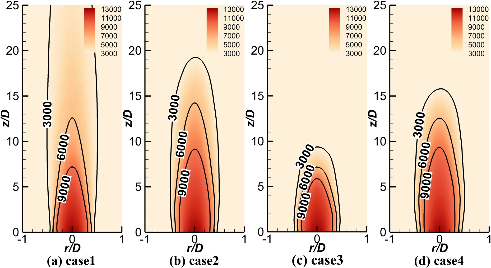
Figure 4.Distributions of mean temperature for cases 1-4.The three black lines represent the contours with mean temperatures of 3000 K,6000 K and 9000 K, respectively.

Figure 5.Distributions of mean argon thermal plasma mass fraction for cases 1-4.The three black lines represent the contours with mean argon thermal plasma mass fractions of 0.3, 0.6 and 0.9, respectively.

Figure 6.Distributions of mean passive scalar for cases 2-4.The two white lines represent the contours with mean passive scalars of 0.3 and 0.6, respectively.
Although the mean argon mass fraction decays faster in the axial direction with increasing velocity in the coflow argon jet inlet, the mean argon mass fraction has a wider influence, especially in the upstream of jet.In addition, the effects on the mean argon mass fraction are detectable in a wider area with increasing width in the coflow argon jet inlet.Figure 6 shows that the trajectory of coflow argon jet also changes significantly and the length of the coflow argon jet decreases appreciably with increasing velocity in the coflow argon jet inlet.The blanket effect [17] of coflow argon jet disappears, and the mixing characteristics between argon thermal plasma and cold air are significantly improved.However, the length and width of coflow argon jet increase appreciably with the increase of the width in the coflow argon jet inlet.As a result, a dense argon atmosphere is created,which leads to higher temperature in the upstream of the case 2 and case 4.
The distributions of normalized mean axial velocityUj/Uc, normalized mean temperature ΔTj/ ΔTc,mean argon thermal plasma mass fraction and mean passive scalar along the thermal plasma jet axis of cases 1-4 are shown in figure 7.Where,the subscript‘c’represents jet axis and the symbol‘Δ’represents difference with cold air parameter, respectively.In order to show the difference between different cases more clearly, logarithmic ordinates are adopted in figures 7(a) and(b).The changes of velocity and width in the coflow argon jet inlet have little influence on the distributions of mean flow field in the jet axis ofz/D<5.This indicates that the turbulent thermal plasma jet also has a laminar high temperature potential core, which is consistent with the previous experiment[43].The decay laws of mean argon mass fraction along the axis of case 2 and case 4 are shown in figure 7(c).The results show that the coflow argon jet is beneficial to create a dense argon atmosphere and reduces the entrainment rate of cold air into the upstream of jet.However, a large number of cold air is entrained into the downstream of jet, causing a sharp increase of decay rate of mean flow field along the jet axis.In addition, increasing the velocity and width in the coflow argon jet inlet can significantly enhance the decay rate of physical quantities in the downstream of jet axis.
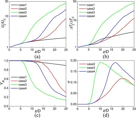
Figure 7.Distributions of normalized mean axial velocity Uj /Uc ,normalized mean temperature ΔT j /ΔT c,mean argon thermal plasma mass fraction and mean passive scalar along the thermal plasma jet axis of cases 1-4.
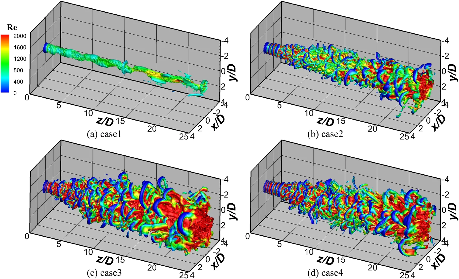
Figure 8.Iso-surfaces ofQ = 5 × 10 5s- 2for cases 1-4, and the color represents local Reynolds number.

Figure 9.Vorticity in the x-direction in the y-z section of cases 1-4.
3.2.Instantaneous flow field
Figure 8 shows the iso-surfaces ofQ= 5 × 10⁵s-2,and the color represents local Reynolds numberwhich is determined according to local dynamic viscosity, density,velocity and diameter of argon thermal plasma jet inlet.As a stable long laminar plasma jet, the phenomena of vortex rolling is not observed,and Reynolds number is very small in the case 1.Under the effect of coflow argon jet, obvious coherent structures are provoked for the cases 2-4, in which the Kelvin-Helmholtz vortexes are main feature.Moreover,increasing velocity and width in the coflow argon jet inlet can enhance the coherent structure of the thermal plasma jet and improve the mixing characteristics between argon and ambient air.

Figure 10.Radial distributions of different physical quantities at different downstream locations of cases 2-4.
Figure 9 shows the x-direction vorticity in the y-z section of cases 1-4.It can also be seen that there is no rolling and breaking of the vortex although the values of vorticity are large for the case 1.After coflow argon jets are applied, the numbers of shear layers are increased from one to two,which are the shear layer between argon thermal plasma jet and coflow argon jet,and the shear layer between coflow argon jet and cold air, respectively.Two shear layers are separated at the jet upstream due to inlet boundary conditions and then merged with the development of the jet, in which the phenomenon of vortex rolling and breaking can be obviously observed.In addition, the intensity of this phenomenon increases with the increase of velocity and width in the coflow argon jet inlet.However, the flow inside argon thermal plasma jet is still very stable until the vortex breaking occurs at a certain location downstream.This location is affected by the velocity and width in coflow argon jet inlet, and increasing the velocity and width in coflow argon jet inlet can promote the transition of argon thermal plasma jet in advance.
3.3.Turbulence statistical characteristics
The reasons of argon thermal plasma transition induced by coflow argon jet are investigated.The radial distributions of normalized axial velocity fluctuationu′/Uj, normalized temperature fluctuationT′/ΔTj, argon thermal plasma mass fraction fluctuationpassive scalar fluctuationφ′and normalized Reynolds shear stressat different downstream locations of cases 2-4 are displayed in figure 10.The two black dashed lines represent the two shear layers mentioned above,and the distance between the two shear layers is equal to the width in coflow argon jet inlet.As a stable long laminar plasma jet, obvious fluctuation cannot be found in base case 1.However,the peaks of fluctuations appear in the shear layer between argon thermal plasma jet and coflow argon jet atz/D=5 of case 2.Then, the fluctuations peaks move to the jet axis.Next,the peaks of fluctuations appear on the jet axis and the Reynolds stress reaches the maximum atz/D=20.Finally,the fluctuations are disappeared due to the process of mixing.Compared with base case 1 that thermal plasma jet issues into the stationary cold air,the coflow argon jet is applied in case 2, which generates the velocity shear between argon thermal plasma jet and coflow argon jet.As a result, Kelvin-Helmholtz instability is provoked, and a laminar jet transforms into turbulent jet.Increasing the velocity and width in coflow argon jet inlet cannot only enhance the turbulent transport between argon thermal plasma jet and coflow argon jet, but also advance the transition of argon thermal plasma jet.It is worth noting that the argon mass fraction fluctuation and passive scalar fluctuation show two peaks atz/D=2, which are caused by the two velocity shear layers.The peaks of argon mass fraction fluctuation and passive scalar fluctuation move much faster to the ambient air than to the axis of argon thermal plasma jet.This may be because the turbulent fluctuations are easily dissipated by the high temperature thermal plasma with high molecular viscosity compared cold ambient air.
4.Conclusions
A numerical code solving argon thermal plasma jets flowing into cold air was embedded based on OpenFOAM.Compared with the laminar argon thermal plasma jet flowing into cold air, the effects of velocity and width in the coflow argon jet inlet on flow and mixing characteristics of thermal plasma jet have been studied by the large eddy simulation methods.The conclusions are summarized as follows:
(1) In comparison to the laminar argon thermal plasma jet flowing into cold air, the Kelvin-Helmholtz instability between thermal plasma jet and coflow argon jet is caused after the coflow argon jet is applied.As a result,a laminar jet transforms into turbulent jet.The length of argon thermal plasma jet reduces significantly, and the gradient of velocity and temperature enhances obviously in the downstream of jet.
(2) Increasing the width in the coflow argon jet inlet can create a dense argon atmosphere.On one hand, more coflow argon rather than ambient air is entrained into the upstream of thermal plasma jet.On the other hand,the specific enthalpy and specific heat of argon are much lower than those of air at the same temperature,causing the higher temperature in the upstream of argon thermal plasma jet.
(3) With the increase of velocity and width in the coflow argon jet inlet, the turbulent transport and coherent structure in the downstream of thermal plasma jet enhance.The mixing characteristics between argon thermal plasma, coflow argon and ambient air are also improved.In addition, the transition from laminar thermal plasma jets to turbulent thermal plasma jets can be advanced by increasing the velocity and width in coflow argon jet inlet.
Acknowledgments
This work is supported by National Natural Science Foundation of China (Nos.12035015 and 12105282).The numerical simulations in this work have been performed on the supercomputers in the Supercomputing Center, University of Science and Technology of China.
猜你喜欢
神剑(2021年3期)2021-08-14
东坡赤壁诗词(2019年1期)2019-04-30
投资有道(2018年9期)2018-10-11
东坡赤壁诗词(2018年3期)2018-07-16
东坡赤壁诗词(2018年3期)2018-07-16
南方文学(2016年4期)2016-06-12
岁月(2016年6期)2016-05-14
微型小说选刊(2014年9期)2014-11-15
小小说月刊·下半月(2014年6期)2014-05-14
可乐(2011年5期)2011-05-11
 Plasma Science and Technology2022年5期
- Plasma Science and Technology的其它文章
- Synthesis of Ag-decorated vertical graphene nanosheets and their electrocatalytic efficiencies
- Upgrade of an integrated Langmuir probe system on the closed divertor target plates in the HL-2A tokamak
- Numerical study of atmospheric-pressure argon plasma jet propagating into ambient nitrogen
- Effects of O2 addition on the plasma uniformity and reactivity of Ar DBD excited by ns pulsed and AC power supplies
- Design and first result of combined Langmuir-magnetic probe on J-TEXT tokamak
- Selective catalytic reduction of NOx with NH3 assisted by non-thermal plasma over CeMnZrOx@TiO2 core-shell catalyst