
Real-time programmable coding metasurface antenna for multibeam switching and scanning
2022-09-24 07:59JiaYuYu余佳宇QiuRongZheng郑秋容BinZhang张斌
Chinese Physics B 2022年9期
Jia-Yu Yu(余佳宇), Qiu-Rong Zheng(郑秋容), Bin Zhang(张斌),
Jie He(贺杰), Xiang-Ming Hu(胡湘明), and Jie Liu(刘杰)
Information and Navigation College,Air Force Engineering University,Xi’an 710077,China
Keywords: programmable coding metasurface,multibeam modulation,real-time control,antenna
1. Introduction
Metasurfaces, artificial electromagnetic (EM) metamaterials constructed in two dimensions, consist of subwavelength elements arranged periodically or nonperiodically over a surface.[1]Due to the unique and intriguing tailoring of EM wave properties, in recent decades, metasurfaces have been extensively and attractively investigated in the frequency domain,varying from acoustic to optical.[2-8]They provide new platforms and play efficient devices for achieving novelty behaviors,such as negative refraction,[4]invisibility cloaking,[6]and optical illusion,[8]that are scarcely possible to tune with natural materials. Moreover, compared to the conventional EM wave modulation method,metasurfaces enjoy low profile,mass and cost,which aids in the development of integrated and light-weight systems.
Recently, coding metasurfaces characterized by binary numbers have evolved as a result of the pursuits in highfreedom metamaterial research. By modifying the topology structure of the unit cells, several relatively fixed coding modes are quantized from EM medium parameters. This approach offers a highly flexible mechanism and a simplified process for designing metasurface functionality.[9-13]In Ref. [12], X-shaped digital metasurfaces are used to convert the circularly polarized (CP) incident waves into bi-foci with direct spatial-power editing, adopting dual geometric phase coding. Furthermore, on the same metasurface platform, active reconfigurable metasurfaces embedded with tunable materials or active components can produce dynamic transitions of diverse EM responses.[14-20]Utilizing a field-programmable gate array (FPGA) control module, in Ref. [18], the author proposed a transmissive metasurface placing two positiveintrinsic-negative (PIN) diodes on the radiating layer, which can efficiently generate orbital angular momentum (OAM)vortex waves with multimode convergent switching. Instead of relying on cell shape modifications to acquire the desired performance,active metasurfaces can actualize versatile propagation features on uniform elements as needed,breaking the constraints of passive structures,whose EM responses are difficult to alter once the design is finalized.This dramatically expands the design freedom and system application of metasurfaces in the reflection half space and reflection-transmission full space. Consequently,such programmable active metasurfaces are paving the way for antennas,imaging,and new wireless interactive systems to be explored.
With the advancement of wireless technology,multibeam antennas are now capable of concurrently covering multiple target areas and achieving multichannel transmission via spatial beam isolation, which promotes the frequency utilization and system communication capacity. Adopting an elaborate phase-shift network, phased array antennas can flexibly construct desired multiple beams by controlling the amplitude and phase of EM waves. However,these widely applied antennas with excellent radiation performance contain complex control circuits and bulky expensive equipment,which are rarely conducive to miniaturized design. Compared with large-scale phased array antennas, the emergence of metasurfaces provides a novel way for multibeam forming. In Ref.[21],when the metasurface patch antenna is separately fed from disparate ports,the narrow beams are shifted in different directions with a suppressed sidelobe. A broadband transmission-mode coding metasurface is also presented in Ref.[22],using frequency variation to steer twin beams in symmetrical directions with a scanning range of 30°-50.5°. Similarly, multiple beams can be guided by reflective and transmissive metasurface antennas by means of geometric partitioning, periodic sequence coding, and amplitude-phase modulation. Although no feed network is required, these passive designs of the unit cell limit the application to a restricted area because the beam direction is relatively fixed once the meta-atom configuration is defined.Driven by the increased demand, programmable metasurface antennas have garnered more attention in the dynamic beams editing. There are now limits in the upper half space of reflective metasurface antennas,[23-26]which can only be dynamically switched for a symmetric multibeam or an asymmetric dual beam,due to design flaws in active devices or differences in multibeam generating methods. Therefore,high-efficiency,low-cost,and flexible multibeam antenna design is still an unremitting pursuit in the wireless field of multichannel transmission and radar detection.
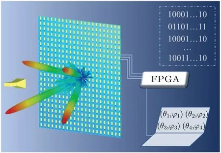
Fig.1. Schematic diagram of the presented real-time programmable multibeam metasurface antenna.
A programmable reflective array antenna based on active metasurface elements (AMSEs) is presented to achieve independent generation and real-time dynamic modulation of multiple beams. This single-feed antenna features radiation and phase-shift functions thanks to an array of 32×32 X-band 1-bit phase-reconfiguration metasurface elements and FPGA control modules. A schematic diagram is depicted in Fig. 1.Without massive algorithm optimization,by utilizing the aperture field superposition strategy, directive beams of different numbers and large coverage angle domains are agilely acquired in the upper half space of the metasurface. Owing to its large array size, simulations and experiments validate that the electronically reconfigurable antenna can execute multibeam scanning and state switching with good performance in directionality and simplicity. It has promising applications in multitarget radar, satellite navigation and other wireless multichannel systems.
2. Design and discussion
2.1. Design of the AMSE
A structural diagram of the AMSE is exhibited in Fig. 2(a), which consists of a classic three-layer metal structure adopting the resonance tuning method. On the top, a copper rectangular patch embedded with a PIN diode,is connected through two metallic via holes to the ground (GND)plate and a DC bias circuit network to switch the resonant state.Serving to fully reflect incident waves,the metal GND is situated in the middle slotted with a single hole,while the DC circuit carrying the bias voltage is printed on the bottom layer.Additionally, Taconic TLX-8(εr=2.55 and tanδ=0.0019)and FR4(εr=4.4 and tanδ=0.025)act as the drilled dielectric substrates between the three metallic layers,whose thicknesses are 1.58 mm and 0.5 mm, respectively. The other parameters of the AMSE structure arep=16 mm,lx=6.3 mm,ly=9.6 mm. In the microwave working band,the equivalent circuit of the selected PIN diode(Skyworks SMP1320)in the on state consists ofRON=0.5 Ω andLON=0.7 nH,and that in the off state consists ofLOFF=0.5 nH andCOFF=0.24 pF,both in series and with low insertion loss.

Fig. 2. (a) Perspective view and geometric structure, (b) simulated amplitude and phase results for AMSE.
The simulated on/off state amplitudes and phases of reflected waves for the proposed AMSE are displayed in Fig.2(b).Simulated by CST Studio Suite,the reflection losses are less than 0.9 dB and the phase difference is 180°±20°in 9.3 GHz-9.5 GHz, which are acceptable for the 1-bit phasereconfiguration requirement. Therefore, equipped with both radiation and phase-switching capabilities, the AMSE can facilely implement the binary states “0” and “1” through its reversed modes.
2.2. Theoretical method
In the schematic diagram of reflective planar array antenna illustrated in Fig.3(a),the spherical EM wave originating from the horn feed needs to form an equal-phase wavefront on the array plane, and the required phase compensation for each elementEmn(m,n)is

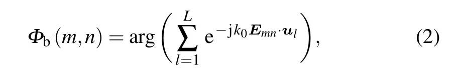
wherek0=2π/λ0denotes the wavenumber in free space.Rfmnis the distance between the feed source phase center and each particle in the reflectarray surface, andFis the focal length.To produce multiple independent-directivity pencil beams in the far field, by exploiting the superposition of the aperture fields correlated with each beam, the distribution after phase summation should satisfy the following relationship:
whereul=(sinθlcosφl,sinθlsinφl)refers to the unit projection vector of thel-th beam aimed at(θl,φl)on thexoyplane.Next,the addition theorem is introduced for conversion into a plane wave and to yield a multibeam,[25]in which the phase distribution on the surface can be expressed as
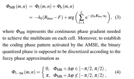
Δφ,a constant,is the reference phase of the metasurface center.Consequently,once the phase coding sequence is acquired,for this metasurface antenna,the far-field multibeam radiation pattern is approximately obtained in accordance with the classical reflectarray antenna theory.[27]
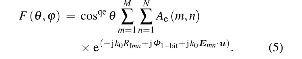
Here,θandφdenote the elevation and azimuth angles in the spherical coordinate system. The amplitude excited on each element is represented byAe(m,n), and the radiation pattern is expressed as cosqeθ,which is based on an approximate cosine mode.
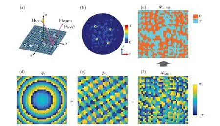
Fig. 3. Generation of a four-beam aimed at elevation and azimuth angles of (25°, 30°), (30°, 135°), (22°, 220°), and (30°, 300°). (a) Reflective planar array antenna schematics. (b)Simulated normalized 2D radiation pattern in the u-v coordinate system. (c)Quantized phase distribution. (d)Compensated phase distribution. (e)Phase distribution after aperture field superposition. (f)Phase distribution after addition.
Assuming the predesigned four-beam is located at elevation and azimuth angles of (25°, 30°), (30°, 135°), (22°,220°), and (30°, 300°), figures 3(c)-3(f) show the phase distributions in each processing step, and the normalized twodimensional(2D)radiation pattern in theu-vcoordinate system (u=sinθcosφ, v=sinθsinφ) is depicted in Fig. 3(b),calculated on the basis of the aforementioned equations.
2.3. Simulation and analysis
To validate the radiation performance, a full-wave calculation is executed using CST Studio Suite with open (add space) boundary conditions, and the far-field monitor is set at 9.37 GHz. A lumped element is selected to emulate the on/off state of the diode on the element surface,i.e., 0 or 1 encoding in Eq. (4). The metasurface section of the reflectarray antenna comprises 32×32 AMSEs,occupying an area of 512 mm×512 mm. With a radiation gain of 10.7 dB and a 3-dB bandwidth of 52°, an X-band linearly polarized horn antenna is mounted 410 mm(F/D=0.8)above the plane as a focal source, making a compromise between the spillover efficiency and the illumination efficiency.[17]By altering the precalculated coding sequence,various scatter patterns will be induced in the upper half space of the two-dimensional sur-
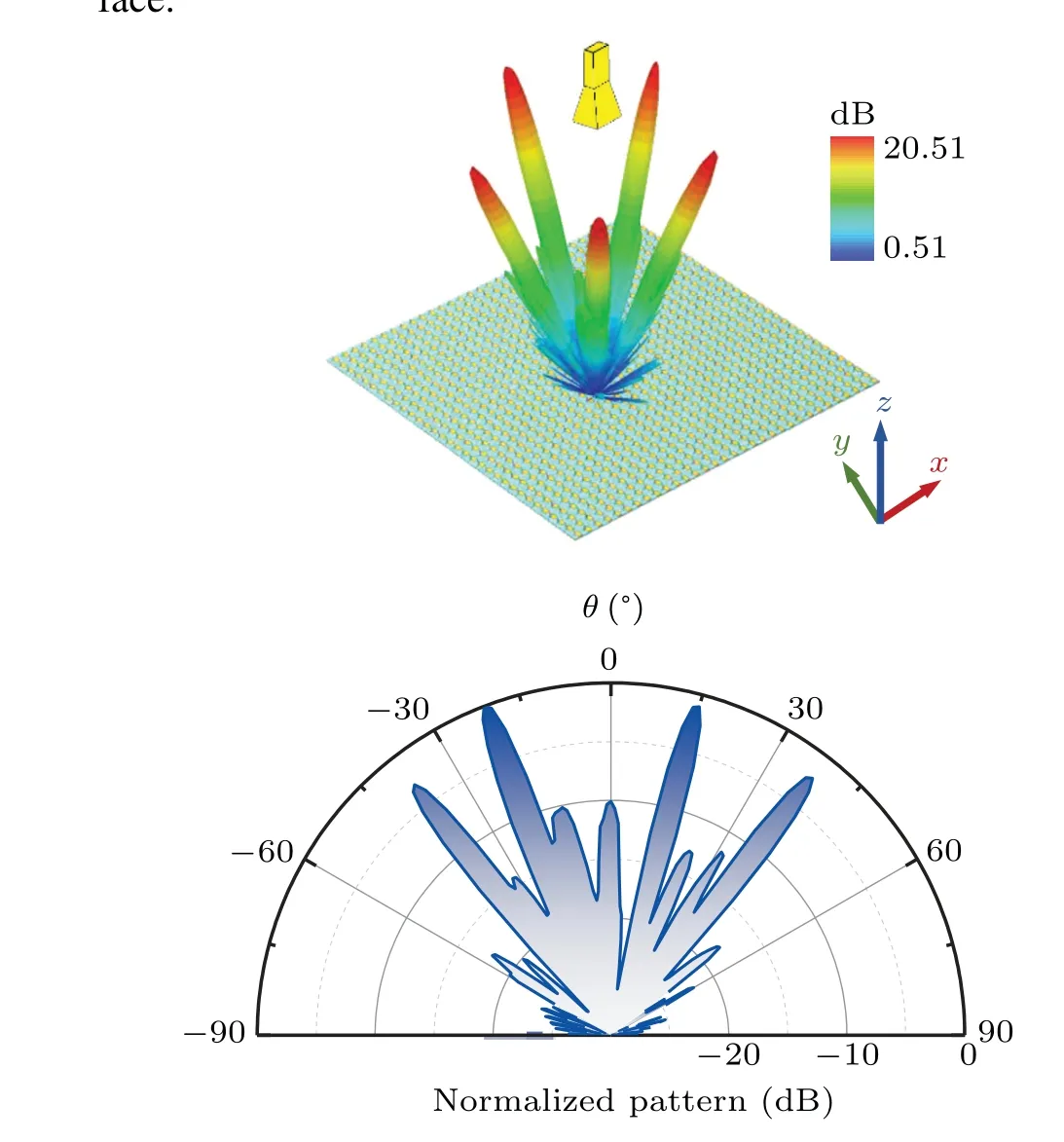
Fig. 4. Simulated radiation patterns of a five-beam and a four-beam: (a)five-beam settling at elevation angle θ =20°, (b) four-beam in φ =135°plane.
The multibeam generation at identical elevation angle and different azimuths is displayed in Fig. 4(a), where the fivebeam settles at an elevation angleθ=20°with even allocation of the azimuths within 360°. From the simulated result, five distinguished main lobes formed with uniform radiation energy. The gain is approximately 21.51 dB and the half-power bandwidth(HPBW)is dispersed around 3.7°for these beams,while the sidelobe level (SLL) is less than-11 dB in each azimuth, suggesting good beamforming capability. In addition,Table 1 gives the average gain of the five equally spaced beams at different fixed elevation angles, which deteriorates with an increscent field angle,as expected. In turn,for beams of the same azimuth and diverse elevation angles, similar results can be obtained. When the directions are preset to(38°,135°),(20°,135°),(15°,315°),and(38°,315°),as in the onedimensional(1D)pattern shown in Fig.4(b),four recognizable pencil-shaped beams are observed. The two laterally symmetric beams pointing at 37.9°and 38.0°have slightly less power than the two asymmetric beams pointing at 20.9°and 15.0°in the middle. The HPBWs of this four-beam vary from 3.7°to 4.0°, which keeps the beam direction deviation within the tolerable range. The simulation indicates that this metasurface reflectarray antenna has the ability to manipulate spherical EM wave illumination into independent-direction multiple beams in both the elevation and azimuth dimensions.
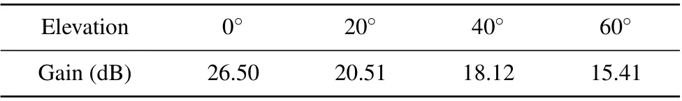
Table 1. Average gain of the five-beam at different fixed elevations.
On the basis of fixed elevation and azimuth angles,to further illustrate the versatility of beam generation, the study is extended to the configuration and dynamic manipulation of beams with arbitrary pointing directions and various numbers.As demonstrated in Figs.5(a)and 5(b),this reconfigurable antenna is capable of producing asymmetric two-beam and threebeam with excellent radiation performance. The simulated beam directions of(11°,225°)and(33°,315°)and of(5°,0°),(20°,180°)and(30°,315°)well match the predesigned angles.More beams than these cases can also be received despite the reduction in scattering power. While the simulated six-beam pointing at(22°,0°),(10°,90°),(10°,270°),(15°,180°),(21°,135°),and(21°,225°)has unambiguous directivity,the overall performance is poorer in terms of variable main lobe magnitude or high SLL, as illustrated in Fig. 5(c). The formation of the seven-beam in Fig. 5(d), whose simulated deflections are (0°, 0°), (11°, 90°), (11°, 270°), (20°, 90°), (20°, 270°),(31°,0°),and(31°,180°),reflects a similar situation. Following that, four-beam with the same preset angles are depicted in Figs.5(e)and 5(f)using 16×16 and 32×32 reflectarrays,respectively. The former beam splits into five beams and fails to create directional pencil beams, in contrast to the distinct scattering state of the latter four-beam,illustrating that the array size has a considerable influence on the aperture field superposition. Furthermore,the coding sequence was calculated using an optimization method with precomputed angles of(0°,0°), (10°, 320°), (15°, 45°), (20°, 150°), and (25°, 240°). In comparison to the unoptimized three-dimensional(3D)pattern(Fig. 5(g)), the optimized 3D pattern (Fig. 5(h) has a smaller SLL and a modest difference in main lobe gain.
Fig.5. Simulated 3D radiation patterns: (a)two-beam pointing at(11°,225°)and(33°,315°);(b)three-beam pointing at(5°,0°),(20°,180°),and(30°,315°);(c)six-beam pointing at(22°,0°),(10°,90°),(10°,270°),(15°,180°),(21°,135°),and(21°,225°);(d)seven-beam pointing at(0°,0°),(11°,90°),(11°,270°),(20°,90°),(20°,270°),(31°,0°),and(31°,180°). Four-beam pointing at(22,45°),(22°,135°),(16°,225°)and(16°,315°)realized with(e)a 16×16 reflectarrays and(f)a 32×32 reflectarrays. Five-beam pointing at(0°,0°),(10°,320°),(15°,45°),(20°,150°)and(25°,240°)simulated by(g)unoptimized sequence and(h)optimized sequence.
From the preceding illustrative examples, large angular pointing and a limited number of multiple beams can be achieved by the programmable coding metasurface antenna.When the number of beams is less than 6,the required beams have comparable gains, and the radiation waveforms are independent and uniform. Meanwhile, since the deviations are all less than 1°, the pointing is acceptable compared to the HPBWs. Nevertheless, as the number of beams grows, the difference in the SLL and the main lobe amplitude shrinks due to the coupling effect between the units.In fact,the multibeam radiation performance is significantly related to the surface dimensions. On the one hand, the more units there are on the surfaces, the lower the SLL generated and the more uniform the gain and waveform of the desired beams. On the other hand, the 1-bit quantization, although facilitating the subsequent control of the physical circuit,causes phase discontinuities that have inevitable effects on the scattering properties of the antenna. Hence, in the numerical theory calculation process, the optimization algorithm is applied to procure the ideal phase distribution, which can promote the radiation energy uniformity of the preset beams in different angular domains and enhance the adaptability of the phase-only metasurface antenna to some extent.
3. Experiment and comparison
3.1. Experiments and results
As an experimental verification, utilizing printed circuit board (PCB) technology, the array antenna prototype shown in Figs. 6(a) and 6(b) is machined and fabricated. It contains a metasurface reflector, a horn feed, and a polymethyl methacrylate support structure. To achieve flexible expansibility in the future, the reflective portion is assembled by four compact metasurface subarrays with a total area of 4×256 mm×256 mm.The metasurfaces cover a two-layer dielectric substrate inlaid with printed circuits, diodes, and FPGA control modules through miniaturized design. As shown in Fig. 6(c), the control modules are made up of 4×4 ALTERA Cyclones connected in parallel to receive and process the coded information from the computer, as well as control the bias circuit voltage to steer the on/off state of the PIN diodes on the 32×32 AMSEs in real time, resulting in the phase state changing once in only every 2µs.
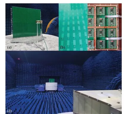
Fig. 6. Metasurface antenna and experiment: (a) manufactured prototype,photographs of(b)AMSEs and(c)FPGA control modules,(d)test environment.
Therefore, the radiation and phase-shift are both integrated into the reflection plane,meaning that the scanning and state switching of the EM wave beams can be dynamically turned in real time by programming. The experiment is implemented in a standard microwave anechoic chamber shown in Fig.6(d),where the antenna prototype is placed on a turntable and a custom-made X-band horn used as the feed source is set in front of the surface geometric center with a focal length ofF=410 mm. Simultaneously,as a detector,a broadband horn antenna is used to test the far-field radiation of the reflectarray antenna. The horns are linked to the two ports of a vector network analyzer(Anritsu MS4644A),and the observation frequency point is selected at 9.37 GHz.
On the one hand,the multibeam scanning function of the metasurface antenna is inspected. Three orthogonal beams,including a symmetric double-beam on theφ=0°plane(xozplane)and a single-beam on theφ=90°plane(yozplane),are scanned with equal gradients in the elevation direction,where the normalized patterns at 10°intervals are selectively shown in Figs. 7(a)-7(c). The simulation and test radiation results are basically in agreement,and the main lobe pointing at each elevation angle remains consistent with the calculation,which proves the accurate dynamic modulation of multibeam scanning in different orientations. Meanwhile, a decreased gain and an increased 3-dB bandwidth would be observed when the orthogonal beams are stepwise separated. The low gain at the 10°azimuth is caused by the blocking effect. On the other hand, the multibeam switching of the programmable antenna is tested. Considering the experimental conditions,the multibeam is chosen to be generated in three observation planes ofφ= 0°,φ= 45°, andφ= 135°, and the far-field patterns are shown in Figs. 7(d)-7(i). In conjunction with copolarization and cross-polarization,the measured results show that the main lobes of the beams are roughly in line with the simulation results,demonstrating the feasibility of multibeam generating and switching multiple beams of different numbers and directivity. Due to factors such as manufacturing tolerances and measurement alignment,together with edge diffraction and specular reflection, there is a certain degree of measurement discrepancies in the experiment results.
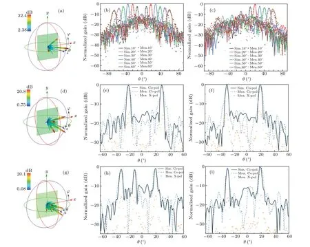
Fig.7. Simulated and experimental results: (a)simulated 3D radiation pattern for three-beam scanning at θ =30°. Simulated and measured normalized gain for three-beam scanning in the φ =0° (b)plane and φ =90° plane(c). (d)Simulated 3D radiation pattern of a four-beam pointing at(29°,45°),(19°,135°),(29°,225°),and(19°,315°). Simulated and measured normalized gain of the four-beam in the φ =45° (e)plane and φ =135° plane(f). (g)Simulated 3D radiation pattern of a five-beam pointing at(10°,0°),(20°,180°),(30°,180°),(19°,135°),and(29°,315°). Simulated and measured normalized gain of the five-beam in the φ =0° (h)plane and φ =135° plane(i).
For the aperture efficiency of the multibeam antenna,with reference to Ref.[23],the modification is expressed as
whereLdenotes the number of generated main beams andArepresents the aperture area. Taking into account the tested gains of the beams, the calculated aperture efficiencies of the generated five-beam and four-beam are 28.6%and 23.7%,respectively. The main loss mainly comes from the spillover effect and element loss.
Despite the slight effect of the DC circuit on the phase distribution, in general, the overall radiation performance of the large-size metasurface antenna is positive, and the feasibility of the electronic-controlled multibeam generation is fully verified by experiments. The superiority of the proposed reconfigurable antenna is that only programmable processing of the FPGA is needed,and both radiation and phase-control can be completed by the antenna surface itself,which is conducive to the development of metasurface integration and low-cost array antennas.
3.2. Performance comparison
Table 2 shows the performance comparison based on metasurface antennas that can generate multiple beams regardless of the feeding surface or radiation surface. Among them, the authors in Ref.[22]achieved a frequency-scanning of symmetric dual beams by varying the input frequency,while scanning of three symmetric fan-beam is realized by switching over multiple feed points in Ref. [28]. Employing only a single feed source, four asymmetric circularly polarized beams are generated by a Berry phase transmission array in Ref. [29], which has excellent aperture efficiency. In addition, the electronically controlled antenna based on a single chip microcomputer can switch the beam state by transforming the coding sequence.[24]The proposed programmable reflectarray antenna has the advantages of a large number of beams,a high aperture efficiency and beam scanning/switching behavior through real-time variable modulation.
Table 2. Comparison with other multibeam metasurface antennas.
4. Conclusion
In this paper,we proposed a programmable coding metasurface antenna that achieves agile-independent modulation of a dynamic multibeam with a single feed. Assisted by the strategies of aperture field superposition and phase discretization, the required coding sequence for an arbitrary pointing multibeam can be instantly obtained by a computer. Under the real-time control of FPGAs,32×32 1-bit phase reconfigurable active metasurface elements form the surface to provide radiation and phase-shift functions. As experimental verification, large angular scanning of orthogonal three-beam and state switching of four- and five-beam demonstrate accurate directionality and favorable HPBW, with an acceptable SLL.Notably,the metasurface antenna enabled by tunable elements has effectiveness and feasibility of EM wave manipulation in real time,and this novel design scheme has promising potential for application in multitarget radar, satellite navigation,and reconfigurable intelligent metasurfaces.
猜你喜欢
金秋(2022年10期)2022-11-25
Chinese Physics B(2022年11期)2022-11-21
理论与创新(2020年1期)2020-04-20
故事会(2018年11期)2018-06-08
美与时代·美术学刊(2018年10期)2018-01-25
新天地(2017年12期)2017-12-21
故事会(2016年11期)2016-06-02
小小说月刊·下半月(2013年2期)2013-05-14
小小说月刊(2013年4期)2013-05-14
当代人(2005年2期)2005-06-30

- Chinese Physics B的其它文章
- Characterizing entanglement in non-Hermitian chaotic systems via out-of-time ordered correlators
- Steering quantum nonlocalities of quantum dot system suffering from decoherence
- Probabilistic quantum teleportation of shared quantum secret
- Spin–orbit coupling adjusting topological superfluid of mass-imbalanced Fermi gas
- Improvement of a continuous-variable measurement-device-independent quantum key distribution system via quantum scissors
- An overview of quantum error mitigation formulas