
New designed helical resonator to improve measurement accuracy of magic radio frequency
2022-09-24 07:59TianGuo郭天PeiliangLiu刘培亮andChaohongLee李朝红
Chinese Physics B 2022年9期
Tian Guo(郭天) Peiliang Liu(刘培亮) and Chaohong Lee(李朝红)
1Guangdong Provincial Key Laboratory of Quantum Metrology and Sensing&School of Physics and Astronomy,Sun Yat-Sen University(Zhuhai Campus),Zhuhai 519082,China
2State Key Laboratory of Optoelectronic Materials and Technologies,Sun Yat-Sen University(Guangzhou Campus),Guangzhou 510275,China
Keywords: trapped ions,helical resonator,magic radio frequency,precision measurements PACS:32.30.Bv,32.10.Dk,37.10.Ty,37.90.+j
1. Introduction
Trapped ions have been verified to be an essential tool in several fields, such as mass spectroscopy,[1-3]atomic frequency standards,[4,5]precision measurements,[6-8]quantum dynamics,[9-11]quantum information processing,[12-16]and quantum simulations.[17-20]The two most major advantages of trapped ions are long coherence time and high controllability of quantum states. Great improvements have been made with trapped ions in recent years in optical clocks,[21,22]magnetometers,[23,24]and gyroscopes.[25]
To trap ions within a radio-frequency (RF) trap, a high RF voltage is delivered to the trap electrodes to yield a deep pseudo potential well. Generally, the RF voltage is coupled to the trap with a helical resonator[26-28]which has a highQ-factor. The helical resonator is the key factor to get perfect impedance matching between the RF generator and the trap, then provides higher voltages per input power for the ion trap. On the other hand, the helical resonator has a narrow bandwidth so as to filter out the power in unwanted applied frequencies, thereby reducing their contribution to motional heating of ions.[29]Apart from the application in the RF trap, the helical resonator is also widely used in different kinds of experiments,such as for the non-destructive resonant detection of eigen-frequencies of charged particles confined in a Penning trap,[30,31]measuring the dielectric property of materials,[32]designing high frequency filter in the communication systems,[33]and applying an intense electric field for ultrasound generation.[34]
Up to now,there is still no experiment achieved a continuous change of the resonant frequency of the helical resonator in a large range and high adjusting accuracy. The main challenge is that the resonant frequency can only be changed in a very small range or discretely by altering the physical properties of the small coil of the helical resonator. However, there are many applications if the resonant frequency of the helical resonator can be adjusted in a large range with highQ-factors.For instance, we can choose an optimal trap drive frequency for longer ion confinement time.Furthermore,an accurate resonant frequency can experimentally be found to eliminate the systematic shifts caused by the micromotion-induced scalar Stark and second-order Doppler effects,[35-37]which will reduce the systematic uncertainty of optical clock.
In this paper, we present an alternative approach to continuously adjust the resonant frequency of the helical resonator in a large range. Correspondingly, the structure of the helical resonator is ingeniously designed to quickly achieve the impedance matching between the signal source and the ion trap whenever the resonant frequency is changed. In the experiment, a lumped element circuit model was developed to depict the properties of the constructed helical resonator. The resonant frequencies andQ-factors under different load conditions were measured to verify our theoretical model. Finally,we evaluate the improvement to the measurement accuracy of magic RF frequency with the experimental data.
2. Theoretical analysis
The Stark and second-order Doppler shifts induced by excess micromotion are the most important parts in the uncertainty analysis of optical clocks. They are interrelated through the driven RF electric field. The total shift of the transition frequency due to micromotion effects can be expressed as the sum of the scalar Stark shift and the second-order Doppler shift,[35]
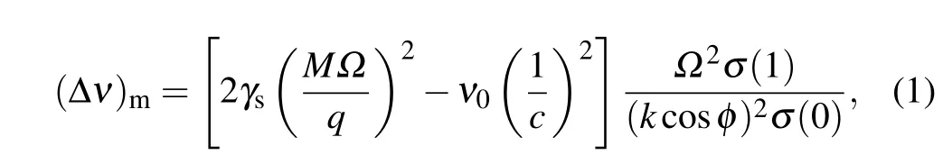
whereγsis the Stark shift rate,Ωis the angular frequency of the trap field,Mandqare the mass and charge of the ion,ν0is the transition center frequency,kis the amplitude of the wave vector of the probe light,φis the angle between the observation direction and the direction of micromotion, andσ(1)/σ(0) is the ratio of the first observed sideband intensity to the carrier line. According to Eq. (1), the scalar Stark and second-order Doppler shifts due to excess micromotion have the comparable magnitude but opposite signs. As a consequence, an appropriate resonant frequency can be fixed to make these two effects cancel each other, but it requires that the resonant frequency of our helical resonator can be continuously adjusted to cover the zero-crossing frequency,which is the so-called magic RF frequency.

In order to evaluate the properties of the constructed helical resonator with capacitive loads,we develop a lumped element circuit model,as shown in Fig.1. Here,Z0is the output impedance of the RF amplifier,Rpis the precision potentiometer,Lais the antenna coil self inductance,Lhis the helical coil self inductance,Rhis the helical coil resistance,Rsis the shield resistance,Rjis the helical coil to shield junction resistance,Ceis the total equivalent capacitance of the resonator without load,Ctis the ion trap capacitance,R1is the contact resistance from the connection between the resonator and the ion trap,Cvis the variable capacitor capacitance,andR2is the contact resistance from the connection between the resonator and the variable capacitor. It should be noted that the capacitance of the connecting wires is not included in our model, which is negligible compared to the capacitance of the ion trap.

Fig.1.Lumped element circuit model of a helical resonator with capacitive loads.
For our helical resonator system, the unloaded resonant frequency can be written as
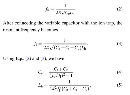
whereCtis a known constant.As a result,we can measure resonant frequencies for different external capacitances and then fit these data linearly to obtain the values ofCeandLh. Then the resonant frequency of the loaded resonator system can be calculated with them.
Another key parameter of helical resonator is theQfactor. In our lumped element circuit model,theQ-factor can be expressed as

According to the above equations,we can estimate the corresponding resonant frequency and theQ-factor as the variable capacitor is consecutively adjusted to change the capacitance.
3. Experimental setup
Figure 2(a) shows the experimental setup to verify our theoretical analysis. The helical resonator connects to an ion trap and a variable capacitor. The variable capacitor connects in parallel with the ion trap. The internal configuration of the constructed helical resonator is shown in Fig. 2(b). The resonator system mainly consists of a copper shield, two copper coils and a precision adjustable potentiometer. The shield is a cylindrical copper tube and has two end caps of matching size.One smaller coil is called antenna coil,with which the RF amplifier connects to the helical resonator through an inductive coupling. Hence the resonator is decoupled from the resistive output impedance of the RF amplifier. The other larger coil is the helical coil, which provides a high RF voltage output for the ion trap. The precision potentiometer mounted to the top end cap is a critical component in the system. It connects in parallel with the antenna coil as shown in Fig.2(c),and its resistance can be continuously changed from the outside of the shield.

Fig. 2. (a) Experimental setup required to change the resonant frequency of the helical resonator. The helical resonator is connected to an ion trap and a variable capacitor, and the variable capacitor is connected in parallel with the ion trap. (b) Internal configuration of the helical resonator. (c) A resonator end cap showing the connection between the antenna coil and the precision potentiometer.
According to the empirical study of Macalpine and Schildknecht,[38]the helical resonator is constructed with shield diameter 114 mm, shield height 151 mm, helical coil diameter 63 mm, helical coil height 94 mm, and helical coil wire diameter 6 mm with 9 helical turns. The antenna coil is wound with 2 mm diameter copper wire. It has 3 turns of diameter 30 mm and the winding pitch is 6 mm.
4. Test results
In order to test our experimental scheme,we measure the resonant frequencies as well as theQfactors under different load conditions. The variable capacitor (Knowles Voltronics NMNT100-4)has a large adjustment range of 2-95 pF,and its capacitance can be finely changed with a slotted screwdriver.The capacitance of the ion trap is 10.5 pF measured by an LCR meter(East Tester 4510).
In the experiment, the RF signal is provided by a signal generator (Rigol DSG815). Then the signal is further amplified by an RF amplifier (Mini-Circuits ZHL-1-2W-S+). To measure the resonant frequency andQ-factor of the helical resonator,a directional coupler(Mini-Circuits ZX30-20-4-S+)is placed between the output port of the amplifier and the input port of the resonator. The reflection signal is monitored by a spectrum analyzer (Keysight N9342C) which connects to the CPL port of the directional coupler. The resonant frequency results in the minimum reflection signal detected by the spectrum analyzer.Then the reflection signal spectrum is measured by sweeping the input frequency. The resonant frequency is exactly the central frequency of the spectrum and theQ-factor is equal to the ratio of the resonant frequency to FWHM of the spectrum.
The variation of resonant frequency along with different capacitances is shown in Fig.3. Figure 4(a)shows the linear dependence of(Ct+Cv)with(fu/fl)2-1. From Eq.(4),the slope of the fitting line represents the total equivalent capacitanceCeof the resonator without load, which is 6.48(2) pF.Figure 4(b) shows the linear variation of (4π2f2l)-1with(Ce+Ct+Cv) and the calculated inductanceLhof the helical coil to be 1.59(1)µH.Utilizing these two values,we have calculated the resonant frequencies for different external load capacitances, as shown in the red curve in Fig. 3. It can be seen that the calculated curve is in good agreement with the experimental result and the resonant frequency is changed by about 17 MHz.

Fig.3. Variation of resonant frequency with capacitance Cv of the variable capacitor. Each data point represents an average of four measurements, and the error bars represent one standard deviation. The red curve is the calculated result.
It should be pointed out that in other groups,[22,39]they also use variable capacitors to change the resonant frequency,but they realize the impedance matching by altering the physical properties of the antenna coil. Due to the limited ability of this method, the impedance matching cannot be well realized when the capacitance changes greatly. Therefore, the resonant frequency can only be changed in a small range. In addition, altering the physical properties of the antenna coil will also slightly change the resonant frequency. Hence,when adjusting the variable capacitor, the resonant frequency will not change consecutively with its capacitance. However, this paper achieves the impedance matching by adjusting the precision potentiometer(BOURNS 3590S),rather than changing the internal structure of the system. As a consequence, the resonant frequency can be continuously adjustable in a large range with the resonator system in Fig.2(a).
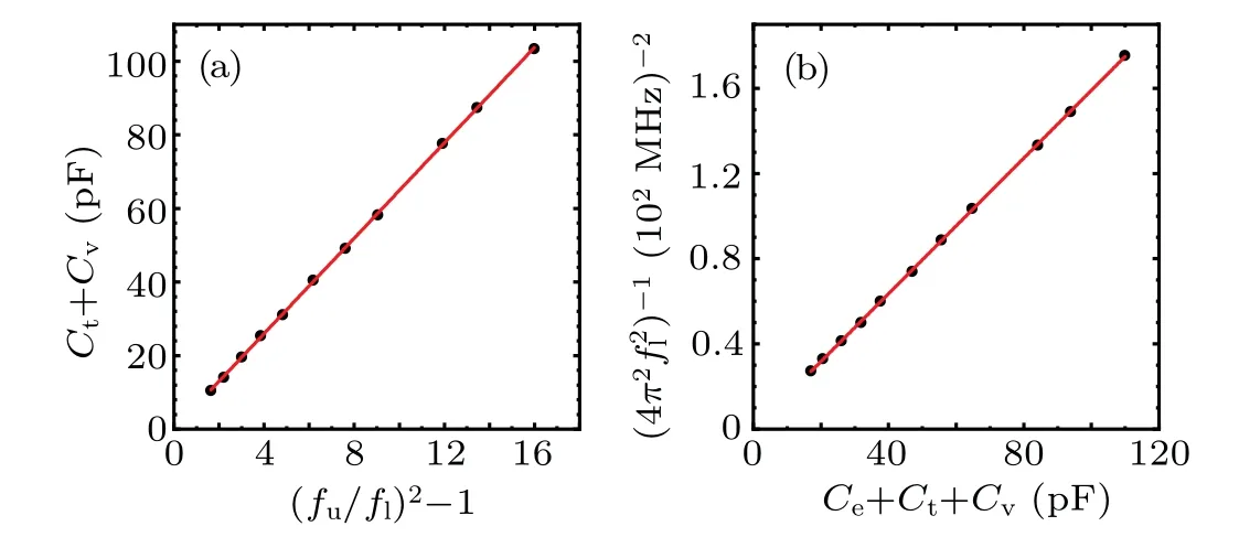
Fig.4. (a)Linear dependence of(Ct+Cv)with(fu/fl)2-1. (b)Linear variation of(4π2 f2l )-1 with(Ce+Ct+Cv).

Fig.5. Variation of Q-factor with capacitance Cv of the variable capacitor. Each data point represents an average of four measurements, and the error bars represent one standard deviation. The black curve is the calculated result.


The long-term stability of the resonator system was also monitored, as shown in Fig. 6. Here, the resonant frequency first fixed to a certain value for some time and then was measured every half an hour within 6 h. The statistical value of the resonant frequency during the period is 14.398(2) MHz.We also changed the resonant frequency and input RF power to different values and made the same measurement. Based on the experimental data, measurement accuracy of each resonant frequency can reach kHz level and fluctuations of RF amplitude have a negligible effect on the measurement of resonant frequency. In the experiment, it can be found that the accuracy of the thousandth pF of the variable capacitor corresponds to the kHz resolution of the resonant frequency. In addition, the adjusting accuracy and stability of the variable capacitor will directly affect the resolution and stability of the resonant frequency. In Ref. [39], Dub´eet al. proposed a method for high-accuracy measurement of the differential static scalar polarizability Δα0by measuring the magic RF frequencyΩ0. There,they operated the test trap with frequencies between 13.5 MHz and 15.0 MHz to cover the zero-crossing frequency of 14.39(25) MHz predicted by Ref. [36], andΩ0was measured by comparing two88Sr+ion trap systems to study the change in micromotion shifts with trap frequency.Now it is assumed that the statistical uncertainty of the trap comparison measurements is small or even ignored. With the resonator system in this paper,the resonant frequency near the zero-crossing frequency can be continuously changed at kHz level. Compared with Ref. [39], the accuracy of the fitting value off0=Ω0/2πcan be improved by at least one decimal place, so that the cancellation level of the micromotion frequency shifts can be further improved. Also, the measurement accuracy of Δα0can be further improved. Therefore,the contribution of the blackbody radiation(BBR)frequency shift coefficient to the uncertainty of ion frequency standard can be further reduced.

Fig.6. Variation of resonant frequency with time. The black triangles represent the measured resonant frequencies at different times,and the red line is the average value.
5. Conclusions
In summary, we have demonstrated a helical resonator whose resonant frequency can be changed in a large range(about 12 MHz to 29 MHz) by adjusting the variable capacitor connected in parallel with the ion trap. This can be verified by treating the helical resonator with its connected loads as a lumped element circuit. Through the distinctive design,optimum impedance matching between the signal source and the ion trap can be quickly achieved by adjusting the precision potentiometer. With the resonator system presented in this paper, the resonant frequency near magic RF frequency can be continuously changed at kHz level. Compared to the results reported by Dub´eet al.,[39]the measurement accuracy of magic RF frequency for88Sr+ion can be improved by at least one order of magnitude, and hence the net micromotion frequency shifts can be further reduced. Promisingly,the differential static scalar polarizability Δα0of clock transition can be experimentally measured more accurately.
Acknowledgements
Project supported by the Key-Area Research and Development Program of Guangdong Province, China (Grant No.2019B030330001),the National Natural Science Foundation of China(Grant Nos.12025509 and 11904418), the Science and Technology Program of Guangzhou, China (Grant No.201904020024),and the Fundamental Research Funds for the Central Universities,China.
- Chinese Physics B的其它文章
- Characterizing entanglement in non-Hermitian chaotic systems via out-of-time ordered correlators
- Steering quantum nonlocalities of quantum dot system suffering from decoherence
- Probabilistic quantum teleportation of shared quantum secret
- Spin–orbit coupling adjusting topological superfluid of mass-imbalanced Fermi gas
- Improvement of a continuous-variable measurement-device-independent quantum key distribution system via quantum scissors
- An overview of quantum error mitigation formulas