
Single-mode lasing in a coupled twin circular-side-octagon microcavity
2022-09-24 08:00KeYang杨珂YueDeYang杨跃德JinLongXiao肖金龙andYongZhenHuang黄永箴
Chinese Physics B 2022年9期
Ke Yang(杨珂) Yue-De Yang(杨跃德) Jin-Long Xiao(肖金龙) and Yong-Zhen Huang(黄永箴)
1State Key Laboratory of Integrated Optoelectronics,Institute of Semiconductors,Chinese Academy of Sciences,Beijing 100083,China
2Center of Materials Science and Optoelectronics Engineering,University of Chinese Academy of Sciences,Beijing 100049,China
Keywords: semiconductor lasers,whispering-gallery mode,coupled microcavity
1. Introduction
Benefiting from high quality (Q) factor and small mode volume,whispering-gallery-mode(WGM)microcavities have attracted considerable interest in both fundamental physics research and practical device applications, such as microlasers and optical filters.[1-7]Among the WGM microcavities with various shapes, including microspheres,[8-11]microdisks,[12-14]microtoroids,[15,16]and microrings,[17,18]symmetric circular microresonators have been demonstrated successfully for ultralow-threshold microlasers, due to their ultrahigh quality WGMs.[19,20]However, the disadvantage of these WGM microcavity structures is their in-plane isotropy resulting in extremely low efficiency of collection in free space. In order to overcome the drawback, various WGM microcavities by carefully modifying the cavity geometries,e.g., spiral-shaped cavities, limac¸on cavities, and the “Face”cavities, were demonstrated experimentally for directional emission.[21-23]
Besides circular resonators cavity with smooth boundaries, regular polygonal WGM microcavities have also been extensively investigated for decades due to their special mode properties.[24-29]Since circular sides as concave reflectors enhance the mode confinement and deformed microcavities have different mode structures, various circular-side polygonal microcavities have been widely studied.[30,31]Circularside square microcavity was designed for single-mode lasing and dual-mode lasing.[32]Various WG-like modes excited in hexagonal microcavities with different corner curvatures were analyzed in detail revealing the limit of theQfactor of the quasi-WGM.[33,34]Circular-side hexagonal microlasers were proposed and demonstrated for enhancing the modeQfactor and realizing single-mode operation.[35]The sensitivity to feedback level of circular-side hexagonal microlaser was numerically simulated, which owns a smaller internal cavity round-trip time compared with distributed feedback laser(DFB) laser.[36]Two different modes excited in an octagonal toroidal microcavity were analyzed,[37]and stable optical coupling in octagonal silica toroid microcavity was experimentally demonstrated.[38]
However, the integrated circular-side-octagon microcavities have rarely been studied. Previously, we proposed a twin circular-side-octagon microcavity(TCOM)laser with octagon’s flat-sideaof 15 µm and deformation degree (curvature)ofM=1.5,and investigated numerically and experimentally the lasing mode control from multiple coupled modes to a single global mode.[39]In this paper, we propose variablecurvature coupled TCOM lasers to comprehensively investigate the different curvatures on modeQfactor and lasing characteristics. Although the change of the curvature appears to be straightforward,it is of great significance to design the appropriate modeQfactors as well as the numbers and interval of lasing modes. The wavelength intervals and the number of the lasing modes for the TCOM lasers are experimentally demonstrated by controlling the curvature of the circular sides,which is consistent with the results of numerical simulations.Finally,lasing performances for the microlasers are characterized and compared.
2. Mode characteristics analysis
Figure 1(a) shows the two-dimensional (2D) structure schematic of a TCOM composed of two identical circularside octagon microcavities(COMs). Figure 1(b)illustrates the schematic diagram of two adjacent sides of a COM, whose geometry is decided by octagon’s flat-sideaand deformation degree (curvature)M=D/f, whereDis the midpointto-midpoint distance, andfis the focal length along the line connecting the midpoints of adjacent sides satisfyingf=Rcosθ/2, withRandθrepresenting the radius of the circular side and the incident angle of the light ray propagating along the line connecting the midpoints of adjacent sides, respectively. The characteristics of the transverse-electric (TE)modes for the TCOMs are numerically investigated based on the two-dimensional (2D) finite element method (FEM)(COMSOL Multiphysics) by solving Maxwell’s equations,due to TE-dominant gain of the compressively stressed multiple quantum wells (MQW) epitaxial wafer used in the experiment. The time dependence of exp(-iωt) is used in the numerical simulation. The microcavity with a refractive index of 3.2 is laterally confined by bisbenzocyclobutene(BCB)layer with a refractive index of 1.54. We set a perfect matched layer(PML)absorbing boundary with a width of 1µm for terminating the simulation window, and the maximum grid size is taken to one-sixth of the mode wavelength (1550 nm) to ensure the accuracy of the computation. The modeQfactors can be calculated throughQ=Re(ω)/|2Im(ω)|, whereωis calculated complex mode frequency.

Fig.1. Schematic diagram of(a)the TCOMs and(b)two adjacent circular-sides of a COM.(c)Microscopic image of the fabricated TCOM lasers with a=15µm and M=0.5. (d)Magnetic field(|Hz|)distributions of the four-bounce modes(Fn)at M=2,where n indicates the order of the mode.
To systematically investigate the effects of different curvatures on the mode characteristics for TCOMs witha=15 µm, we first consider the influence of the curvature to cavity B by setting cavity A as a loss cavity with the imaginary part of the refractive index(ΔIm(nA))of 2×10⁻³. The high-Qmode patterns for TCOMs with different curvatures are four-bounce modes, which are the fundamental (zeroth-),first-,second-,third-,fourth-,and fifth-order marked byF,F1,F2,F3,F4,andF5,etc.,respectively. Figure 1(d)illustrates the corresponding magnetic field amplitude distributions for the four-bounce modes of TCOM atM=2, which are similar to that at other deformation degrees. The four-bounce modes are formed by the total reflection of the light ray through four reflection points. Figures 2(a)-2(f) show the simulation results of modeQfactors versus mode wavelengths atMof 0,0.5,1,1.5, and 2 for TCOMs, respectively. The longitudinal mode intervals for four-bounce modes decrease with the increase ofM,owing to the increasing optical paths,i.e.,the longitudinal mode intervals atMof 0,0.5,1,1.5,and 2 are 7.35,7.27,7.21,7.17,and 7.08 nm,respectively.
As shown in Fig. 2(a), the modeQfactors are 2.0×10⁴and 1.9×10⁴forFmodes ofM=0 at wavelengths of 1548.42 and 1555.77 nm, respectively. The wavelengths forF1mode are found at 1554.68 nm with the modeQfactor of 3.6×10³,and the wavelength interval betweenF1mode andFmode at 1555.77 nm is 1.09 nm. ForM=0.5, the wavelengths ofFmodes are 1548.92 and 1556.19 nm,with corresponding modeQfactors both around 1.5×10⁷in Fig. 2(b). ModeQfactors ofF1andF2modes at the wavelengths of 1552.85 and 1549.50 nm are 6.4×10⁵and 5.0×10⁴,respectively,and the wavelength intervals betweenF0mode at 1556.19 nm andF1,F2modes are 3.34 and 6.69 nm, respectively. AtM=1, we findFmodes at 1549.67 and 1556.88 nm with corresponding modeQfactors of 2.3×10⁴and 2.2×10⁴in Fig.2(c).ModeQfactors of modesF1andF2at the wavelengths of 1552.04 and 1554.41 nm are 8.9×10³and 4.9×10³,respectively,with the wavelength intervals betweenF0mode at 1549.67 nm andF1,F2modes are 2.37 and 4.74 nm,respectively. Figure 2(d)depicts that theF,F1,F2,F3,andF4modes have modeQfactors in the order of 108,107,106,105,and 104atM=1.5,with the corresponding wavelengths of 1550.33 (1557.50), 1551.57,1552.78, 1554.00, and 1555.23 nm, respectively. The wavelength intervals betweenF0mode at 1550.33 nm andF1,F2,F3,F4modes are 1.24, 2.45, 3.67, and 4.90 nm, respectively.AtM=2,Fmodes are found at 1550.93 and 1558.01 nm with corresponding modeQfactors of 1.1×10⁸and 7.2×10⁷, as indicated in Figs. 2(e).F1,F2,F3,F4, andF5modes are at the wavelengths of 1550.97, 1551.02, 1551.08, 1551.13, and 1554.18 nm corresponding to the wavelength intervals of adjacent modes of 0.05, 0.06, 0.05, and 0.05 nm, as shown in Fig. 2(f), as well as the enlarged view of Fig. 2(e) around 1551.0 nm. Actually, the TCOM withM=0 has no deformation,which means that there is no light convergence effect of the circular side. Compared with the TCOMs atMof 0,the TCOMs atMof 0.5,1,1.5,and 2 have enhanced modeQfactors,owing to the light confinement effect of the concave mirrors. The ray dynamics of TCOM withM=1 is chaotic,and the regular islands in the phase space are destroyed.[31]The destruction of regular island results in degradation of mode quality factors and dispersed mode field distributions. Therefore,the modeQfactors for the case ofM=1 are much smaller than those withMof 0.5,1.5,and 2.

Fig. 2. Mode Q factors versus the variation of mode wavelengths for the TCOMs with a=15 µm: (a) M=0, (b) M=0.5, (c) M=1, (d)M=1.5,and(e)-(f)M=2 by FEM,respectively. (f)The enlarged view of the mode Q factors versus wavelength around 1551 nm at M=2.

Fig. 3. Mode wavelengths and Q factors for the global modes versus M. The solid and hollow symbols correspond to mode wavelengths and Q factors, respectively. The inset is the magnetic field distribution for the global mode of TCOM at M=0.5. The circle and triangle stand for different longitudinal modes of the global modes.
As both microcavities are at ΔIm(nA)=ΔIm(nB)=0,we can find a global mode with the mode pattern of an 8-shaped pattern with modeQfactor around the order of 104or 105in the variable-curvature TCOMs,in addition to traditional fourbounce modes. Meanwhile,the magnetic field distributions of the four-bounce modes are the same as those at ΔIm(nA)=0 and ΔIm(nB)=2×10⁻³and are nearly zero overlap between the modes confined in the cavities A and B. Figure 3 shows the mode wavelengths andQfactors versusMfor the global modes. The magnetic field distribution for the global mode of TCOM atM=0.5 is shown in the inset of Fig.3. The global mode is formed by the total reflection of the light ray through six reflection points in the whole coupled cavity. The longitudinal mode intervals for the global modes atMof 0,0.5,1,1.5,and 2 are about 3.7,3.6,3.6,3.6,and 3.6 nm,respectively.The longitudinal-mode wavelength intervals for the global modes at differentMare half of that of four-bounce modes,because the optical path of the global mode is twice the interval of fourbounce modes. We can conclude that global mode with modeQfactor around the order of 104or 105distributing throughout coupled microcavity is insensitive to curvature compared to the four-bounce mode.
3. Device fabrication and lasing characteristics
The TCOM lasers witha=15 µm andM=0, 0.5, 1,1.5,and 2 are fabricated on an AlGaInAs/InP epitaxial MQW wafer with a photoluminance wavelength of about 1517 nm,with similar fabrication processes as in Ref. [40]. The active region of the laser wafer consists of six pairs of compressively strained multiple quantum wells, with 6-nm-thick quantum wells and 9-nm-thick barrier layers. Use plasma-enhanced chemical vapor deposition (PECVD) to deposit a SiO2layer,and standard contacting photolithography and inductively coupled plasma(ICP)etching techniques are employed to the coupled cavity with a deep etching depth of about 4 µm. After the BCB planarization, a 4 µm wide isolation trench is accomplished by ICP etching the p-InGaAs ohmic contact layer off between both microcavities to guarantee mutual electrical isolation. A Ti/Pt/Au p-electrode pad is deposited by e-beam evaporation, then an Au/Ge/Ni n-electrode pad is deposited by magnetron sputtering. The microscope image of the fabricated TCOM laser withaof 15µm andMof 0.5 is illustrated in Fig. 1(c). The devices are mounted on an AlN sub-mount for testing with a temperature of 291 K controlled by a thermoelectric cooler(TEC).

Fig.4. Output optical powers collected by an multi-mode fiber(MMF)versus the injection current for(a)COM-A and(b)B lasers at M of 0,0.5,1,1.5,and 2,respectively.
Both COM lasers of the TCOM laser can work at the free-running with injection currents applied to the two cavities separately. The MMF coupled powers as functions of the injection current are measured and plotted in Figs. 4(a) and 4(b)for COM-A and COM-B lasers atMof 0,0.5,1,1.5,and 2, respectively. As shown in Fig. 4(a), the threshold currents are 34, 31, 25, 22, and 20 mA atMof 0, 0.5, 1, 1.5, and 2 for COM-A laser, with the corresponding maximum output powers 80, 100, 98, 137, and 131 µW, respectively. We can obtain that the power trend of COM-B laser is similar to that of COM-A laser, but there are differences between them in Fig. 4(b). The deviation in the fabrication process leads to slightly different cavity shapes and surface roughness between COMs,though both COMs are designed to be identical and fabricated together. The powers oscillate as the current increases,due to the mode hopping caused by thermal effect and multi-longitudinal and multi-transverse mode emission.
The lasing spectra of COM-A laser forM=0,0.5,1,1.5,and 2 are measured by an optical spectrum analyzer with a resolution of 0.02 nm using MMF,as illustrated in Figs.5(a)-5(f),respectively. The fundamental,first-,second-,third-,and fourth-order four-bounce modes are marked by circle, triangle, square, rhombus, and pentagram symbols, respectively.The longitudinal mode intervals atM=0, 0.5, 1, 1.5, and 2 are 6.4, 6.4, 6.4, 6.1, and 6.0 nm, respectively. ForM=0,0.5, 1, 1.5, and 2, the lasing spectra of COM-A laser exhibit multi-longitudinal-mode and multi-transverse-mode emission,due to the effect of light confinement of the concave mirrors.AtM=0 andI=55 mA, multi-longitudinal-mode lasing is observed,and the fundamental and the first-order four-bounce transverse modes are found at 1525.16 and 1524.25 nm, respectively, with corresponding transverse mode interval Δλ01of 0.91 nm in Fig. 5(a). Both transverse mode intervals and longitudinal mode intervals are smaller than the simulation values since the refractive index is fixed at 3.2 and the dispersion of the material is not considered in the simulation.AtM= 0.5 andI= 50 mA, three-transverse-mode lasing for the fundamental, first-, second-order four-bounce modes is observed at 1535.73, 1532.94, and 1530.05 nm, with corresponding transverse mode intervals Δλ01and Δλ02of 2.79 and 5.68 nm, respectively, as shown in Fig. 5(b). AtM=1 andI=55 mA, three-transverse-mode operation for the fundamental,first-,second-order four-bounce modes are obtained at 1530.32, 1532.46, and 1534.70 nm, with transverse mode intervals Δλ01and Δλ02of 2.24 and 4.38 nm in Fig.5(c), respectively. AtM=1.5 andI=55 mA,four-transverse-mode emission for the fundamental, first-, second-, third-, fourthorder four-bounce mode is achieved at 1519.32, 1520.47,1521.65, 1522.84, and 1524.02 nm, with Δλ01, Δλ02, Δλ03,and Δλ04of 1.15, 2.33, 3.52, and 4.70 nm, respectively, as shown in Fig.5(d). AtM=2 andI=50 mA,four-transversemode emission is realized at 1521.40, 1521.64, 1521.92, and 1522.10 nm, with the corresponding wavelength intervals of the adjacent transverse modes being 0.24,0.52,and 0.70 nm,respectively, as illustrated in Figs. 5(e) and 5(f). The difference between the experimental results and simulation ones is large because the mode wavelength intervals are so small that the mode competition among transverse modes with large overlap regions is intense. Therefore,it is hard to distinguish the specific mode order of the lasing modes. The experimental results show that the relative positions and the numbers of the lasing modes are consistent with the simulation results in Figs.2(a)-2(f). The variable curvature provides space for diverse high-Qlasing modes and mode control of the lasers.Furthermore, such multi-mode TCOM lasers may be promising for the bandwidth enhancement of chaotic lasers in the future.
Single-mode lasing is achieved in variable-curvature TCOM lasers with the injection currents applied to the two microcavities simultaneously. We have demonstrated and revealed that the global mode distributed in the whole cavity consumes a large number of injected carriers and suppresses the lasing of four-bounce modes.[39]The detailed lasing spectra of the single-mode lasing are illustrated in Figs.6(a)-6(e)for the TCOMs atMof,0.5,1,1.5,and 2.AsIa=554 mA andIb=45 mA,single-mode emission for TCOMs ofM=0 with the side mode suppression ratio(SMSR)of 30 dB is achieved at 1543.9 nm in Fig. 6(a). For TCOMs ofM=0.5, singlemode operation occurs at 1574.6 nm with the SMSR up to 32 dB atIa=50 mA andIb=63 mA,as shown in Fig.6(b).For TCOMs ofM=1, the SMSR of 32 dB of single-mode lasing is realized at 1562.4 nm atIa=62 mA andIb=64 mA in Fig. 6(c). AtIa=55 mA andIb=76 mA, single-mode emission for TCOMs ofM=1.5 with the SMSR of 31 dB is achieved at 1567.8 nm as shown in Fig.6(d). AtIa=60 mA andIb=61 mA,the SMSR of 36 dB of single-mode emission for TCOMs ofM=2 is realized at 1547.7 nm as illustrated in Fig.6(e).
Finally,we investigate the linewidth characteristics of the TCOM lasers witha=15µm andM=2. The short-delayed self-heterodyne interferometer (SDSHI) technique has been demonstrated to be a good and mature method to obtain the accurate value for the laser linewidth.[41-44]Figure 7(a)illustrates the detailed spectra for COM-A laser atIa=61 mA after erbium-doped fiber amplifier(EDFA)and bandwidth pass filter(BPF),and the wavelengths of four lasing modes are found to be 1529.9, 1530.3, 1530.5, and 1530.6 nm. Figure 7(b)shows the beating spectra obtained by filtering out the four lasing modes through BPF.Modes 1,2,and 4 have obvious intensity peaks with mode 3 of almost no peak,the resolution bandwidth(RBW)of 3 MHz, and the video bandwidth(VBW)of 10 kHz.The full widths at half-maximum(FWHMs)of modes 1,2,and 4 are obtained by Lorentz curve fitting as 79.9,78.4,and 44.2 MHz,corresponding lasing linewidths of 40.0,39.2,and 22.1 MHz, respectively. Therefore, a higher intensity of the lasing mode means higher power and a corresponding narrower linewidth.

Fig.5. Lasing spectra for COM-A laser with(a)M=0 at 55 mA,(b)M=0.5 at 50 mA,(c)M=1 at 55 mA,(d)M=1.5 at 55 mA,and(e)-(f)M=2 at 50 mA.(f)The enlarged view of lasing spectra around 1551 nm at M=2. The fundamental,first-,second-,third-,and fourth-order four-bounce modes are marked by circle, triangle, square, rhombus, and pentagram symbols, respectively, and the solid and hollow symbols correspond to different longitudinal modes.

Fig.6. Detailed lasing spectra characteristics for the TCOMs with M=0,0.5,1,1.5,and 2 at(a)Ia=55 mA and Ib=45 mA,(b)Ia=50 mA and Ib=63 mA,(c)Ia=62 mA and Ib=64 mA,(d)Ia=55 mA and Ib=76 mA,and(e)Ia=60 mA and Ib=61 mA,respectively.
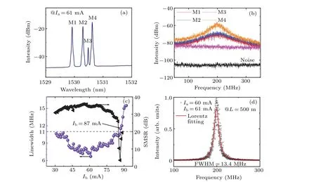
Fig. 7. (a) Optical spectra after amplifier and filter and (b) beating signals for four lasing modes of the COM-A laser with a=15 µm and M=2 at Ia =61 mA.(c)Linewidths and SMSR as functions of Ib at Ia =60 mA.(d)The normalized RF spectrum(circles)and Lorentzian fitting(line)to the measurement data at Ia=60 mA and Ib=61 mA.
The linewidths and the SMSRs versusIbare illustrated in Fig. 7(c) measured by a delay fbier length (L) of 500 m at fxiedIa=60 mA, with the TEC temperature of 286 K. The dominant lasing mode redshifts with SMSRs over 30 dB from 1547.7 to 1550.3 nm, asIbincreases from 31 to 86 mA. AsIbincreases from 31 to 61 mA, the linewidth decreases from 10.6 to 6.7 MHz, with the SMSR growing from 31 to 36 dB.WhenIbincreases from 61 to 86 mA,the linewidth increases from 6.7 to 10.5 MHz, and SMSR varies from 36 to 30 dB.The linewidths less than 11 MHz can be obtained withIbincreasing from 31 to 86 mA. In general, the linewidth is inversely correlated to SMSR, as higher SMSR means higher lasing mode power and lower noise from other modes.[45]Figure 7(d) illustrates the normalized radio frequency (RF) signal of the lasing mode, accompanied by the Lorentz fit curve shown by the red solid line, with the FWHM of 13.4 MHz and linewidth of 6.7 MHz. The linewidth of the single-lasing mode for the TCOM laser is small, compared to the normal microlasers of 20-50 MHz.[45,46]
4. Conclusion
In summary, we have proposed and demonstrated variable-curvature TCOM lasers for manipulating the lasing mode. The simulation results show that the passive TCOM has two types of modes: four-bounce and global modes; and modeQfactor,mode number,and wavelength intervals of different transverse modes of four-bounce mode can be manipulated by adjusting the curvature. Curvature affects slightly the modeQfactor of the stable global mode in variable-curvature TCOMs, with values of 104or 105. At current injection into single microcavity, two-mode, three-mode, three-mode, fivemode,and four-mode lasing are experimentally achieved with deformation from 0 to 2, matching well with the numerical simulation. Stable single mode of the global mode lasing with SMSRs of 30, 32, 32, 31, and 36 dB is realized at the deformation of 0, 0.5, 1, 1.5, and 2, respectively. In addition,the linewidth of 6.7 MHz for the single-lasing mode is measured with the deformation of 2. We believe that the proposed variable-curvature TCOM lasers suitable for planar integration have significant potential as a compact light source for photonic integrated circuits based on the manipulation of modeQfactor and lasing characteristic.
Acknowledgements
Project supported by the Strategic Priority Research Program, Chinese Academy of Sciences (Grant No. XDB43000000), the Key Research Program of Frontier Sciences,Chinese Academy of Sciences(Grant No.QYZDJSSW-JSC002), and the National Natural Science Foundation of China(Grant Nos.61874113,61875188,and 61935018).
- Chinese Physics B的其它文章
- Characterizing entanglement in non-Hermitian chaotic systems via out-of-time ordered correlators
- Steering quantum nonlocalities of quantum dot system suffering from decoherence
- Probabilistic quantum teleportation of shared quantum secret
- Spin–orbit coupling adjusting topological superfluid of mass-imbalanced Fermi gas
- Improvement of a continuous-variable measurement-device-independent quantum key distribution system via quantum scissors
- An overview of quantum error mitigation formulas