
An equivalent model of discharge instability in the discharge chamber of Kaufman ion thruster
2022-11-17 02:59FengTIAN田丰KanXIE谢侃LongMIAO苗龙FuwenLIANG梁福文JiahuiSONG宋家辉SongBAI白松andNingfeiWANG王宁飞
Plasma Science and Technology 2022年11期
关键词:宋家
Feng TIAN(田丰),Kan XIE(谢侃),Long MIAO(苗龙),Fuwen LIANG(梁福文),Jiahui SONG(宋家辉),Song BAI(白松)and Ningfei WANG(王宁飞)
School of Aerospace Engineering,Beijing Institute of Technology,Beijing 100081,People’s Republic of China
Abstract The industrial application of the Kaufman ion thruster in its arc stage is limited owing to the instability of the discharge pulse.Presently,a complete prediction model that can predict the discharge pulse in the high-current stage does not exist.In this study,a complete prediction model for the pulse in the ion thruster is established using the zero-dimensional plasma discharge model and equivalent circuit model.The zero-dimensional plasma discharge model is used to obtain the corresponding plasma parameters by calculating the beam current,discharge current,voltage,and gas flow under actual working conditions.The input parameters of the equivalent circuit model are calculated using empirical formulae to acquire the estimated discharge waveforms.The pulse waveforms obtained using the model are found to be consistent with the experimental results.The model is used to evaluate the process of rapid changes in plasma density.Additionally,this model is employed to predict changes in the pulse waveforms when the volume of the discharge chamber and grid plate transmittance are changed.
Keywords:Kaufman ion thruster,arc discharge,pulse phenomenon,zero-dimensional plasma discharge model,equivalent circuit model
1.Introduction
A hollow cathode discharge is a unique gas discharge form seen in a cathode cavity.Owing to its high working pressure,high electronic density,and low maintenance voltage[1-4],it was first used as a spectral light source for high-resolution spectral analysis.Later,it was used in metal-vapor ion laser systems,electric propulsion,surface treatment,electrodynamic tether,and other applications[5-9].For electric propulsion,it is widely used in ion thrusters and Hall-effect thrusters[10-14].There are usually some discharge instabilities in the discharge process from the discharge chamber of ion thruster,especially under high-current conditions,which significantly affects its industrial application.
When the ion thruster discharge current is a few hundred mA,it enters the arc discharge stage.Domonkos and Williams[15]measured the pulse phenomenon of annular discharge,and found that the pulse of annular discharge is particularly intense under the conditions of high current,low flow,and high voltage.
Subsequently,Goebel[16,17]reported the presence of highenergy ions in a large current pulse.The potential of these highenergy ions was higher than the voltage applied by the circuit.As the spatial and discharge conditions of the discharge chamber of ion thruster were different,the amplitude and frequency of the pulse were also different.Concurrently,in an experiment designed to calculate the beam current and discharge loss,Goebel found that the ion engine also exhibits discharge instability.
Extensive researches have been conducted to determine the cause of high-current discharge instability,and considerable progresses have been made.For example,Williams and Farnell[18]established a probe system to measure the space potential of the discharge chamber of ion thruster under different anode conditions.They found the presence of a visible discharge pulse,which indicates that the discharge pulse is unrelated to the anode condition.Gabriel[19],through an experimental study,suggested that the discharge instability is mainly related to the filling rate of neutral gas.
Furthermore,Jorns[20]used the average frequency quasilinear model and experiments to study the acoustic potential pulse oscillations of discharge chamber of ion thruster at a current of 100 A.It was proposed that the ion-acoustic potential pulse oscillations are affected by abnormal electron Landau damping,ion Landau damping,and ion collision frequency,in which the first two terms are more significant.Shunsuke[21]examined the discharge-pulse oscillations by studying the three discharge forms of the hollow cathode(plume,spot,and diffuse).It was identified that the discharge current pulse is affected by the discharge forms of the ion thruster.The effects of the gas flow rate,discharge current,and different types of anode discharge chambers on the ion thruster potential pulse have also been studied[10,22,23].The ion thruster discharge is affected by different types of anode discharge chambers.It was also confirmed that the instability of ionization causes ionization-like high-amplitude potential pulses.Space ions play a decisive role in this kind of space potential pulse.Nelson[24]studied the potential pulse caused by ion-acoustic waves.It was experimentally confirmed that potential pulse oscillation should be universal in a high-current working condition.
The pulse phenomenon of the discharge chamber of ion thruster in the high-current stage is crucial.It exerts a significant influence in practical engineering,but presently,there are no theories that can accurately predict the discharge instability pulse in the arc stage.In this paper,a complete discharge-pulse prediction model is proposed,which combines the equivalent circuit model and the zero-dimensional plasma discharge model,to investigate the discharge-pulse instability in the arc stage.The plasma density and temperature are obtained by using the zero-dimensional model,and then the obtained parameters are brought into the equivalent discharge model to obtain the discharge oscillation curve.The established model is also used to study the effects of different discharge chambers on the pulse characteristics of high-current ion thruster ionization discharge.
2.Experimental system and calculation model
2.1.Experimental system
The schematic for experimental measurement of the ion thruster pulse is shown in figure 1.A 6 cm Kaufmann ion thruster is used to study,which consists of four parts:the main cathode,the discharge chamber,the optical system and the neutral cathode,and the specific structural parameters are shown in the figure 1.The emission probe is used in this experiment to measure plasma potential.It is a cylindrical tungsten wire with a diameter of 0.127 mm,and the length of the tungsten wire in contact with the plasma is 4 mm.The vacuum chamber has a stainless-steel body with a diameter of 1.8 m and a total length of 4 m.The pumping speed of the diffusion pump is 5000 l s-1,and the ultimate vacuum degree in the chamber is 5×10⁻⁴Pa.
The optical system adopts double grid structure,which is composed of screen grid and acceleration grid.The structural parameters of the discharge chamber and grid are shown in table 1 and table 2.
The diagnostic and measuring systems include an emission probe,high-speed camera,current probe(Tektronix TCP0030A),voltage probe(Tektronix TPP1000),the capacitance tester(YTC720,with the range of 2-2000μF)digital oscilloscope(Tektronix DPO4104B,with a measurement accuracy of±1%)and automatic capacitance tester.The emission probe is used to measure the plasma potential,a high-speed camera is employed to capture the discharge forms,and no filter is used when capturing the discharge form.The current and voltage probes are used to measure discharge current and discharge voltage,respectively,and the sampling rate is 100 MHz.
2.2.Analytical model
2.2.1.Zero-dimensional plasma discharge model.Goebel[16,17]constructed a zero-dimensional plasma discharge model based on the two basic formulae governing neutral gas density and discharge current conservation along with a series of simplifications of ion thruster discharge.The model can beused to solve for plasma density,temperature,primary electron density and neutral gas density.

Table 1.Structure parameters of discharge chamber of ion thruster.
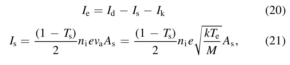
The plasma densityneandTecan be calculated as follows:
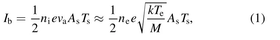
whereIbis the beam current,Asis the screen grid area,Tsis the grid transparency,ni,neare ion and electron densities,respectively,eis electron charge,vais the ion acoustic velocity,kis the Boltzman constant,Teis electron temperature,Mis ion mass.Since the beam current and structural parameters in equation(1)are known,it is only necessary to construct a formula of plasma density and temperature,and then they can be calculated.
For an unmagnetized plasma,the currentIiflowing out of the plasma in any direction can be obtained from the Bohm current:
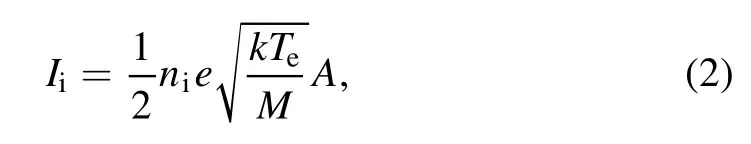
whereAis internal surface area of discharge chamber.Ions in the discharge chamber are produced by both the primary electrons and by the tail of the Maxwellian distribution of the plasma electrons.The total number of ions producedIpin the discharge in particles per second is given by:

whereIpis the number of ions produced per unit time,n0is the neutral atom density,Vis the discharge chamber volume,σiis the ionization cross section,veis the plasma electron velocity,np,vpare the primary electron density and velocity,andvpis considered the same asve.The terms in the brackets are ionization cross section averaged over the distribution of electron energies,which is usually called the reaction rate coefficient.
The total ion production rate is equal to the total ion absorption rate:
Simultaneous equations(1)-(4)can be obtained:
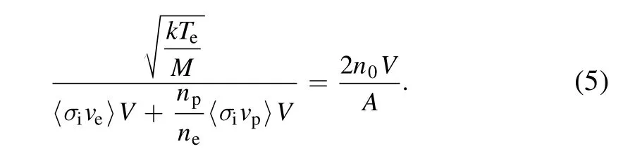
In the equation(5),〈σive〉 and〈σivp〉 are the functions of plasma temperature and density[17].Ifn0andnpcan be found,or they are represented byneandTe,equation(5)will be only related to plasma density and temperature.
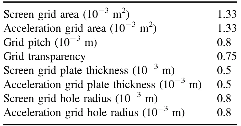
Table 2.Structure parameters of ion thruster grids.
The neutral gas density is calculated as follows:
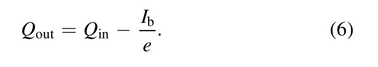
In the equation,Qoutis the flow rate of neutral gas leaving the discharge chamber,Qinis the gas flow into the discharge chamber.The flow rate of neutral gas leaving the discharge chamber is:
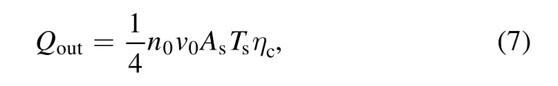
wherev0is the velocity of neutral atoms,ηcis the Clausing coefficient(in general,ion thruster grids will have Clausing factors on the order of 0.5).The propellant utilizationηmdrefers to the propellant that needs to be consumed to generate a unit beam current,and is a key parameter to measure the performance of the discharge chamber,which is defined as:
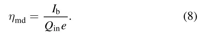
Simultaneous equations(6)-(8)can obtain the expression of neutral gas density as:

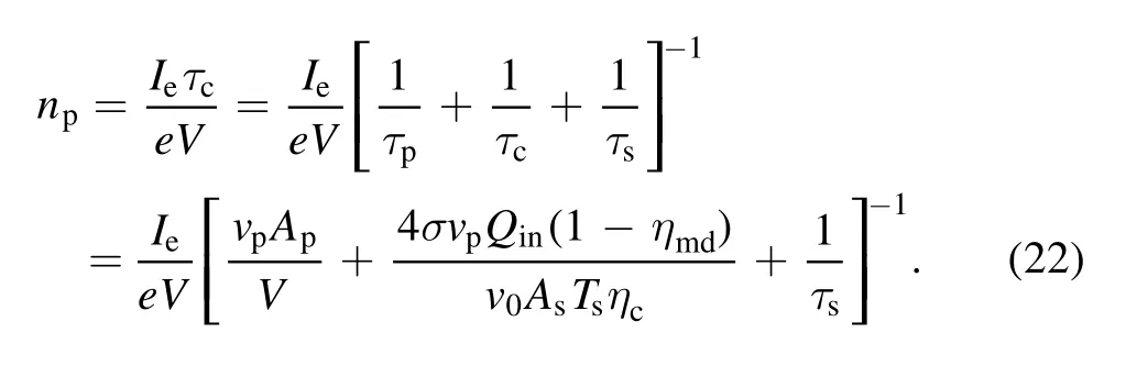
The primary electron density in equation(5)can be evaluated from the total primary electron confinement time in the discharge chamber.The emitted currentIefrom the hollow cathode is:
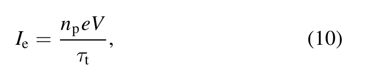
whereτtis the total primary confinement time that addresses all of the primary electron thermalization and loss mechanisms.The ballistic confinement time for direct primary loss to t he anode,τp,was given in the following equations:

whererpis the primary electron Larmor radius,Apis the loss area for the primaries,B0is the magnetic field strength at the tip of the ring,vpis the primary electron velocity,eis the electron charge,andLcis the total length of the magnetic cusps(sum of the length of the cusps).
It is assumed that the primary electrons have undergone an inelastic collision with the neutral gas and have lost sufficient energy such that they are then rapidly thermalized with the plasma electrons.The mean time for a collision between the primary and a neutral gas atom to occur is given by:
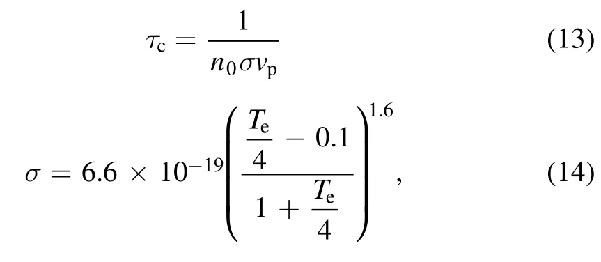
whereσis the inelastic collision cross section of electrons and neutral particles[16,17],n0is substituted into the above formula,the mean collision time for primary electrons is:

Finally,primary electrons can also be thermalized by equilibrating with the plasma electrons.The time for primary electrons to slow into a Maxwellian electron population was derived by Spitzer[25]and is given by:
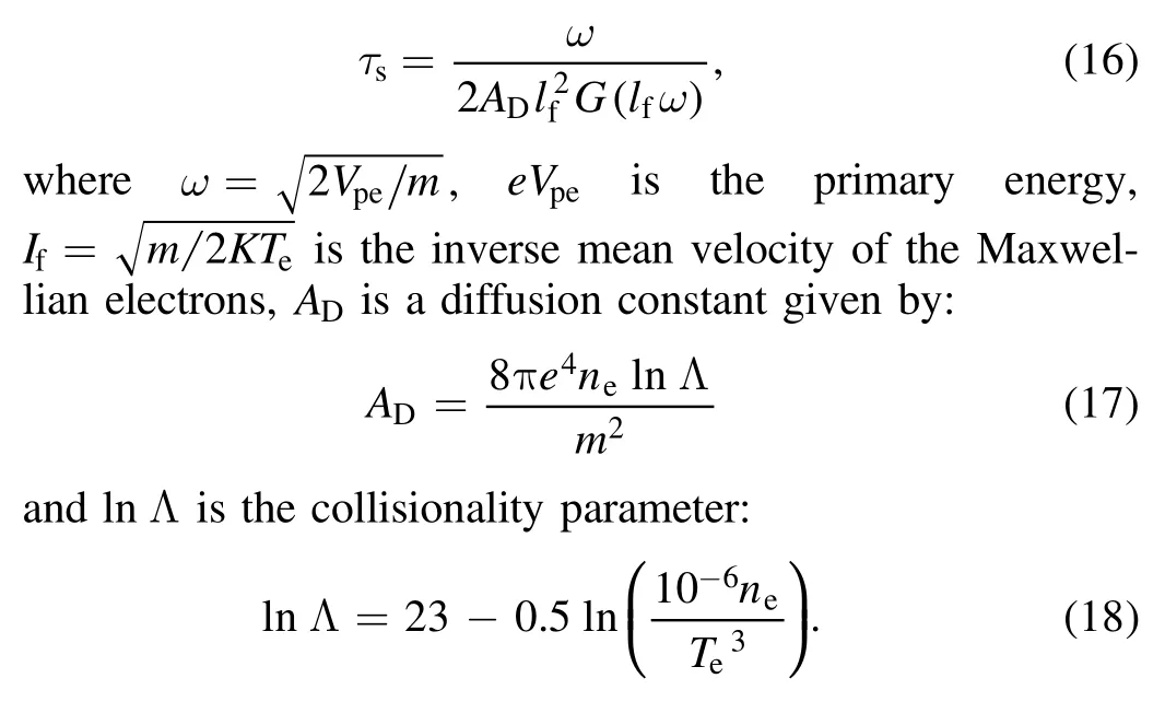
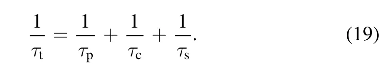
The function()ωG lfis defined in the appendix of[16],and a curve fit to Spitzer’s tabulated values(in CGS units)for this function is provided.The total primary electron confinement time can be found from:
The current emitted from the hollow cathode is:
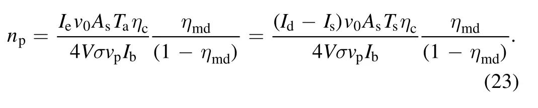
whereIsis the screen current,Idis the discharge current andIkis the ion current back to the cathode,the primary electron density is derived by the above formulae:
Assuming that the primary electron loss directly to the anode is negligible,the electron equilibration time is long,and the ion current flowing back to the cathode is small,then the above equation can be written as:
The plasma density and temperature can be obtained by solving equations(1)and(5).
2.2.2.Equivalent circuit model.Aubertet al[26]made significant contributions to the construction of this equivalentcircuit model in the low-current stage.Based on this model,we propose an equivalent-circuit model of the high-current stage.Figure 2 shows an equivalent circuit model of a highcurrent stage,mainly used to study the ionization-type pulse phenomenon,which is similar to the equivalent model for the low-current stage.The negative electrode of the power supply is at the same potential as ground.The capacitance in the circuit model only depends on the structure of the ion thruster discharge chamber[25],the capacitance tester is used to measure the discharge chamber of ion thruster capacitance,and the measured value is 355 μF.VAis the voltage across the capacitor,V0andRbare the DC power supply voltage and the current limiting resistor,respectively,RP1andRP2are the plasma resistances at different discharge stages,respectively.Since the stray capacitance introduced by the circuit and measurement probe is much smaller than that of the highcurrent hollow cathode,it is ignored.In a discharge pulse,when the voltage is rising,it is regarded as a charging process,and when the voltage is falling,it is regarded as a discharging process.The switchK switches between connecting the charging resistor and the discharging resistor,and the voltage at the switching time is the threshold voltage.When the discharge voltage increases to the maximum(charging process),the switch is connected to RP2,the discharge voltage decreases(discharging process),and when the discharge voltage reaches the minimum,the switch is connected to RP1.The above is one cycle of discharge oscillation.
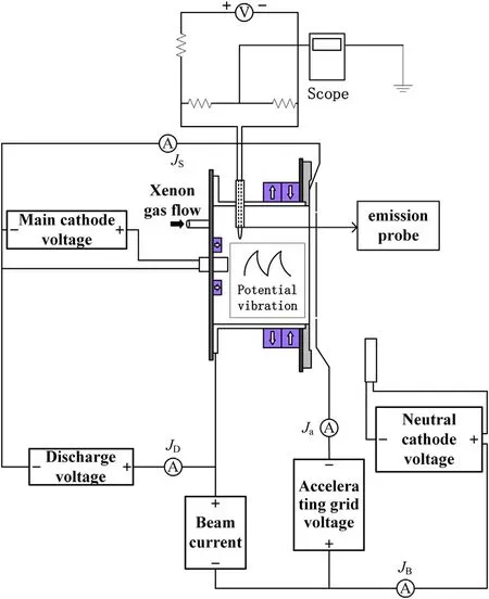
Figure 1.Schematic of an ion thruster.
Figure 2.Charge-discharge model of high-current HCD pulse equivalent circuit.
Figure 3.The simulated process.
Figure 4.Comparison of the anode voltage test waveforms and the simulated sinusoidal waveforms.
Figure 5.Comparison of experimental and simulated anode voltage waveforms.
The basic node current relationship and loop voltage relationship are easy to obtain:
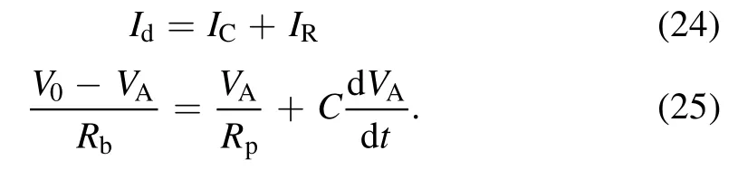
According to these two equations,the equivalent circuit model is constructed.The external power supply is represented by a constant voltage source and a currentlimiting resistor.The pulse of the discharge current-voltage observed in the experiment is equivalent to the charging and discharging process of the capacitor in the circuit.
Scholars initially used a single sinusoidal function to simulate the discharge voltage pulse.The frequency and amplitude of the sinusoidal function were based on the data obtained in the experiment.Thus,the discharge voltage pulse can be represented as the average of discharge voltage plus this sinusoidal function:

where()A Teis the amplitude related to electronic temperature,and α is a frequency coefficient that determines the discharge pulse.The discharge period can be derived from experimental data and can be expressed as:
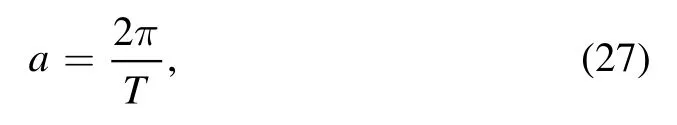
where T is the period of the pulse measured in the experiment.
The amplitude of the anode voltage is mainly related to the electron temperature,due to its influence on the ionization rate and ionic sound waves.When the electron temperature is high,it promotes the excitation of ionization and the growth of ionic sound waves,leading to the increase of the potential pulse amplitude.When the electron temperature is low,the amplitude of the pulse caused by ionization and ionic sound waves decreases,leading to a decrease in the potential pulse amplitude.In practical experiments,when the discharge is in its plume stage with a low plasma density and high electron temperature,the amplitude of the anode pulse will be relatively large.Conversely,when the discharge form is in its spot stage with a high plasma density and a low electron temperature,the relative pulse amplitude is low.There is an essential relationship between the amplitude of discharge voltage pulse and electron temperature.The results show that there is a linear relationship between the pulse amplitude and the ionization rate[26].Reference[25]shows that the ionization rateTherefore,it can be seen that the expression of the potential pulse amplitude is as follows:
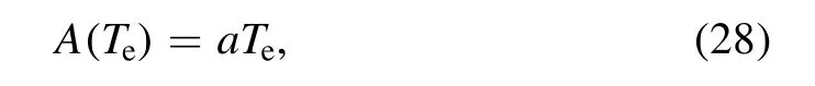
where the electron temperature Teis in eV,the amplitude A(Te)is in V,and according to the experiment[22],it can be seen thata=0.5.
When the structure of the hollow cathode is fixed,the equivalent charge-discharge resistance of the discharge chamber of ion thruster can be expressed as:
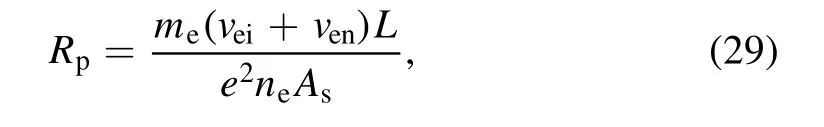
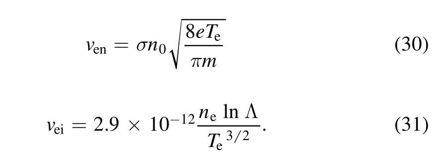
where,meis the electron mass,L is the length of discharge chamber,A is the cross-sectional area of discharge chamber(screen grid area),the Ahhas been corrected as As,veiis the collision frequency of electrons and ions,venis the collision frequency of electrons and neutral particles.They can be calculated as follows[16,17]:
The plasma density is related to the gas flow rate,the discharge current,and the discharge voltage working condition parameters through the zero-dimensional plasma discharge model.Therefore,the equivalent resistance value can be obtained from the working condition parameters.Since the plasma density changes with the changes in discharge voltage,the equivalent plasma resistance can be divided into an equivalent plasma charge resistance and an equivalent plasma discharge resistance.In the specific solution process,for the equivalent charging resistance,the discharge current of the input of the model is taken as the value of the maximum.Contrarily,for the equivalent discharge resistance,we take the value of the minimum.For both,the remaining conditions should be consistent.Thus,we can obtain the equivalent charging and discharging resistances,respectively.
These parameters are closely related to microscopic parameters.However,microscopic parameters are coupled with each other,making it impossible to calculate the microscopic parameters corresponding to working conditions directly.The zero-dimensional plasma discharge model adopts two formulae related to conservation of neutral gas density and discharge current.This can be used to solve for neutral and plasma parameters,corresponding to each specific working condition parameter.The corresponding microscopic parameters are then determined.Thus,the function of obtaining microscopic parameters from working condition data is attained.
The equivalent-circuit model can estimate the waveforms of the discharge pulse of the discharge chamber of ion thruster in the high-current stage,and the zero-dimensional plasma discharge model provides a method for calculating the microparameters,such as the plasma density and the temperature,from the working condition parameters.It is,therefore,possible to estimate the discharge-pulse waveforms of the high-current stage,when the input of the equivalent circuit model is obtained from the microscopic parameters.The simulated process is shown in figure 3.
3.Experimental verification and simulation analysis
3.1.Experimental verification
The following set of experimental data is used:the discharge current changes in the range of 5 A,the average of it is 5 A,the beam current is 0.3 A,the supply voltage is 25 V,the value of the current-limiting resistance in the experiment is 1.14 Ω,the gas flow rate of the cathode is 10 sccm,and the discharge supply gas is 2 sccm.
Figure 4 demonstrates the comparison between the experimental measurement waveforms of the discharge voltage pulse and the sinusoidal simulation waveforms.The charging and discharging processes are the same for the sinusoidal simulation,however,this is not aligned with the actual simulation.The increase and decrease in the voltage correspond to the decrease and increase in the internal average potential,respectively.The corresponding physical mechanism is a process of slow accumulation and rapid dissipation of positive ions.Therefore,the times when the anode voltage rises and falls are not equal.However,the simulation of this sinusoidal pulse is highly dependent on the experimental data,and thus,does not have much significance in practical engineering.
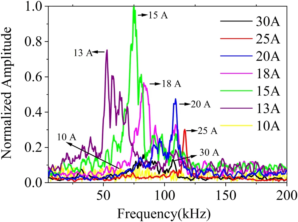
Figure 6.Current frequency variation of the ion thruster.
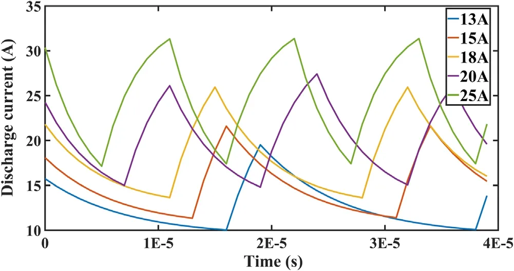
Figure 7.Current pulse diagram for changing charge resistance.
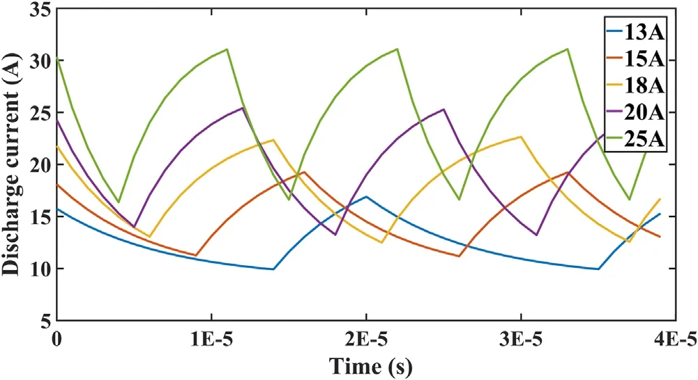
Figure 8.Current pulse diagram for changing discharge resistance.

Figure 9.Current pulse diagram for changing equivalent capacitance.

Figure 10.Charging resistance versus discharge current.
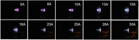
Figure 12.Discharge forms.
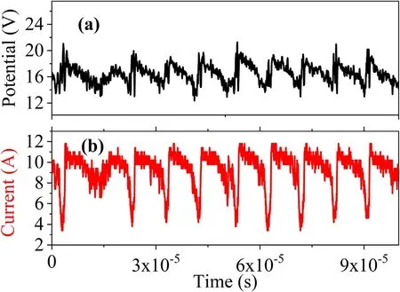
Figure 13.Ion thruster(a)potential and(b)discharge current waveforms.
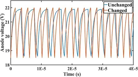
Figure 14.Discharge voltage pulse diagram under different discharge chamber volumes.
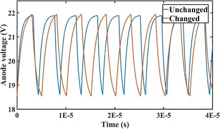
Figure 15.Discharge voltage pulse diagram under varying gate plate transmittance.
The zero-dimensional model and the equivalent circuit model introduced in section 2 are simulated,as a result,the electron temperature is 3 eV,the()A Teis 1.5 V,and the current amplitude can be obtained.Substituting the corresponding current into the resistance prediction formula,the corresponding plasma densities are 5×10¹⁷m-3and 1.4×10¹⁷m-3,thus,the charge and discharge resistances are 6.3 Ω and 17 Ω,and the equivalent capacitance value is 355 μF.
In figure 5,the waveforms of the corresponding experimental measurement are compared with those of theoretical simulation.The experimental simulation results fit well with the actual situation,thus addressing the two limitations in the sinusoidal simulation model.
3.2.Analysis of charge-discharge characteristics
As shown in figure 6,after the application of the fast Fourier transform,the relationship between the discharge current and pulse frequency is obtained at various discharge currents.The five key points are extracted from figure 6 for later simulation,(13 A,60 kHz),(15 A,75 kHz),(18 A,85 kHz),(20 A,110 kHz),and(25 A,120 kHz).
When the discharge voltage pulse amplitude,discharge current,current-limiting resistance,and hollow cathode structure parameters are known,the controlled variable method is used by changing only the charging resistance,discharge resistance,and equivalent capacitance.The waveforms are consistent with the frequency measured in the experiment,thereby,revealing the change in the charging resistance,discharging resistance,and frequency of discharge.The simulated results are shown in figures 7-9.
In three sets of equivalent resistance simulation experiments,figures 7 and 8 illustrate the corresponding frequency by adjusting the charging resistance and the discharging resistance,respectively,while figure 9 shows the same frequency by adjusting the capacitance value.The change in charging resistance and discharging resistance is shown in figure 10.The change in the equivalent capacitance is shown in figure 11.
From figures 10 and 11,it can be observed that,with an increase in the discharge current,the plasma equivalent resistance decreases.The plasma resistance changes slowly with discharge current from 13 to 15 A,and 20 to 25 A,and rapidly from 15 to 20 A.However,the frequency of the current pulse decreases with the increase in capacitance,and this change is uniform.The recorded discharge forms are shown in figure 12.
When the discharge current is low,it is in the form of a purple plume.With the further increase in discharge current,the plasma plume grows,reaching a maximum at approximately 15 A.Upon further increasing the discharge current,the plume shrinks to a point near the cathode exit,which is caused by the radial contraction of plasma.When the plasma plume contracts,as seen in figure 12,a bright region is formed between the anode and the cathode.Subsequently,the plasma becomes more compact because the excited ionization region becomes more compact,and when the discharge current increases,the electron temperature decreases rapidly.
The equivalent resistance is inversely proportional to the plasma density.Therefore,when the discharge current increases,the plasma density increases,and thus,the resistance decreases.When the current is between 15 and 18 A,the plasma plume shrinks radially,the plasma density increases rapidly,and thus the resistance changes rapidly.However,the equivalent capacitance depends only on the hollow cathode structure.The change in equivalent capacitance will not change the discharge current and will not cause any change in potential difference.Therefore,changing only the equivalent capacitance will not change the form of the discharge.The capacitance and discharge-pulse frequency will change evenly.
Some experimental waveforms obtained using the experimental system are shown in figure 13.The spatial potential pulse waveforms are synchronized with the oscillation variation of the cathode current waveforms.This indicates that the discharge oscillation is really related to the change in spatial plasma(ion/electron)density.
3.3.Effect of discharge volume and gate plate transmittances
3.3.1.Effect of discharge volume.When other conditions are known,the volume of the discharge chamber is reduced from 47.7 to 10 cm2,the discharge-pulse curve is calculated using the prediction model,and the change of the discharge-pulse curve is shown in figure 14.
When the volume of the discharge chamber decreases from 4770 to 1000 cm2,the discharge voltage pulse frequency increases from 238 to 463 kHz when other conditions remain unchanged.This is due to the increase in the plasma density when the volume of the discharge chamber decreases.Moreover,when other conditions remain unchanged,the decrease in discharge chamber volume will lead to an increase in the electron temperature and thus an increase in the pulse amplitude of discharge anode voltage.
3.3.2.Effect of gate plate transmittances.When other conditions are satisfied,the transmittance of the grid plate in the discharge chamber increases from 0.7 to 0.8.The dischargepulse curve is calculated using the predictive model.The changes in the discharge-pulse curve are illustrated in figure 15.
When the other conditions remain unchanged,and the transmittance of the gate plate increases from 0.75 to 0.85,the pulse frequency of anode voltage decreases from 238 to 206 kHz.This is due to the decrease in the plasma density.Furthermore,the grid plate transmittance has little effect on the electron temperature,thus,the pulse amplitude of the discharge voltage changes slightly.
4.Conclusion
A theoretical model for predicting the discharge-pulse waveforms is proposed,which aims at addressing the phenomenon of the ionization discharge pulse in the discharge chamber of ion thruster in the arc phase.The effects of plasma density and temperature on the amplitude and frequency of the pulse waveforms are theoretically analyzed.Parameters,such as discharge current,voltage,and gas flow rate,can be used to estimate the amplitude and frequency of the pulse waveforms.
The simulation is performed using the established predictive model,and the waveforms obtained from the simulation are consistent with those obtained from the experiment.It was experimentally found that,when the discharge current is between 15 and 18 A,the plume shrinks radially near the cathode outlet,and the plasma density will increase rapidly in this range.The equivalent resistance in the simulation model showed that the turning point of the resistance change was similar to the current corresponding to the rapid change in plasma density.
The established model is also used to study the effects of different discharge chambers on the pulse characteristics of highcurrent hollow cathode ionization discharge.When the volume of the discharge chamber reduces,while other parameters are unchanged,the plasma density increases,and the temperature rises.Thus,the discharge-pulse frequency and amplitude tend to increase.When the grid plate transmittance increases and other parameters are constant,the plasma density reduces.Thus,the discharge-pulse frequency tends to reduce.
Acknowledgments
The authors acknowledge the financial support from National Natural Science Foundation of China(Nos.11402025,11475019,and 11702123),the National Key Laboratory of Science and Technology on Vacuum Technology &Physics(No.ZWK1608),the Advanced Space Propulsion Laboratory of BICE and Beijing Engineering Research Center of Efficient and Green Aerospace Propulsion Technology(No.LabASP-2018-03).
ORCID iDs
猜你喜欢
今日农业(2022年13期)2022-09-15
中国中医药信息杂志(2022年3期)2022-03-16
扬子江(2019年3期)2019-05-24
民间故事选刊·上(2018年4期)2018-04-19
中国信用(2017年5期)2017-05-25
中外文摘(2014年4期)2014-03-22
故事会(2011年7期)2011-04-14
俪人·蜜糖版(2009年4期)2009-05-12
 Plasma Science and Technology2022年11期
- Plasma Science and Technology的其它文章
- Comparative study of pulsed breakdown processes and mechanisms in self-triggered four-electrode pre-ionized switches
- Wide-range characteristics of beam perveance and saddle point potential of LIPS-200 ion thruster
- Discharge and jet characteristics of gliding arc plasma igniter driven by pressure difference
- Investigation of stimulated growth effect using pulsed cold atmospheric plasma treatment on Ganoderma lucidum
- Nanosecond laser preheating effect on ablation morphology and plasma emission in collinear dual-pulse laser-induced breakdown spectroscopy
- Interaction of an unwetted liquid Li-based capillary porous system with high-density plasma