
In situ calibrated angle between the quantization axis and the propagating direction of the light field for trapping neutral atoms
2024-02-29 09:17RuiJunGuo郭瑞军XiaoDongHe何晓东ChengSheng盛诚KunPengWang王坤鹏PengXu许鹏MinLiu刘敏JinWang王谨XiaoHongSun孙晓红YongZeng曾勇andMingShengZhan詹明生
Chinese Physics B 2024年2期
关键词:刘敏
Rui-Jun Guo(郭瑞军), Xiao-Dong He(何晓东), Cheng Sheng(盛诚),Kun-Peng Wang(王坤鹏), Peng Xu(许鹏), Min Liu(刘敏), Jin Wang(王谨),Xiao-Hong Sun(孙晓红), Yong Zeng(曾勇),†, and Ming-Sheng Zhan(詹明生)
1Henan Key Laboratory of Laser and Optoelectronic Information,National Center for International Joint Research of Electronic Materials and Systems,School of Electrical and Information Engineering,Zhengzhou University,Zhengzhou 450001,China
2State Key Laboratory of Magnetic Resonance and Atomic and Molecular Physics,Innovation Academy for Precision Measurement Science and Technology,Chinese Academy of Sciences,Wuhan 430071,China
Keywords: quantization axis,trapping laser,angle,compensating magnetic fields
1.Introduction
Single neutral atoms in tightly focused optical dipole traps (ODTs) are being intensively developed for studies of quantum simulation[1,2]and quantum computation.[3–6]A practical quantum simulator or computer relies on coherent manipulation of quantum bits (qubits).Moreover, coherence times are of great importance for applications in the fields of quantum metrology[7–9]and precision measurements.[10]Although atomic states have excellent coherence properties in an isolated environment, the inherent differential light shifts(DLSs) of neutral atoms in optical tweezers induced by the trapping laser field cause a strong inhomogeneous dephasing effect.[11–14]To suppress this detrimental effect,a magicintensity trapping technique was developed recently[15]and used extensively.[16–18]
In order to create effective magic-intensity trapping for microwave clock transitions, an external bias magnetic fieldBbiasis arranged to be strictly parallel to the circularly polarized trapping laser field.In this way, the trapping laser field induces a fourth-order hyperpolarizabilityβ4that is expressed in terms of the degree of circular polarization,hyperfine splitting and the vector polarizability of the ground state, which makes the DLS dependence on the trapping laser intensity parabolic.Owing to the parabolic dependence, at a magicintensity trap depth, the first-order sensitivity of the DLS to the trapping laser intensity variations from the whole ODT volume is eliminated so that the coherence time of87Rb qubits is substantially enhanced[15]and the coherence times of the mixed-isotope qubits are substantially enhanced and balanced to be nearly 1 s.[18]Different from the widely used linear polarization trapping laser, for atoms in the circularly or elliptically polarized magic-intensity ODTs,trapping laser fields in general give rise to vector light shifts that are equivalent to the effect of a fictitious magnetic fieldBfict[19–30]scaling linearly with the trap depth.If theBbiasdefined quantization axis is not aligned with the trapping laser, the total magnetic field combined withBfictandBbiaswill vary with the trap depth.During the measurement of the DLS parabolic curve by conventional Ramsey interferometry for the magic-intensity trapping of85Rb qubits,microwave radiation is used to coherently manipulate the clock transitions of the ground states.With a fixed microwave antenna,the projection value of microwave power on the total magnetic field also varies with the trap depths,resulting in an inconsistency of Rabi frequencies between the ground states in ODTs with different trap depths.In turn,the difference in Rabi frequencies leads to imperfect measurements of the conventional Ramsey interferometry, which is detrimental to the accurate measurement of hyperpolarizability.In addition,fluctuations of the microwave power may also cause large errors in the coherent manipulation of single qubits in the magic-intensity ODT array.[16]Therefore,it is crucial to calibrate the angle accurately.
Since it is difficult to accurately measure the magnetic fields in the ODTs by using a traditional magnetometer, researchers have developedin situmeasurement methods to measure the magnetic field vector.In the study of optically parallel readout of multiple qubits with high fidelity,the presence of atoms and their internal states are minimally altered by utilizing a circular polarization probe laser.[31,32]It is required that the propagation direction of the probe laser must be strictly aligned with the quantization axis.A procedure adapted from Ref.[33]was used to minimize the angle,which uses the atoms themselves as probes to optimize the magnetic field vector.The quantization axis is created byBbiasalong theZdirection, further adjustment of the magnetic field by theX–Ycompensating magnetic fields is required.The87Rb qubits are first optically pumped to|F=2,mF=2〉by a circularly polarized beam.One of theσ+-polarized probe lasers is tuned to|2〉↔|2′〉and optically pumps the qubits into the dark state|2,2〉.When the alignment is optimal,the dark state|2,2〉can only couple off-resonantly to|3′,3′〉.If there is any mismatch,the dark state|2,2〉mixes with the bright states and scatters photons,eventually depumping into|1〉,which can be measured by the destructive blow-away measurement.The optimum values for theX–Ycompensating magnetic fields were experimentally optimized by minimizing the survival probability such that only 13% of the qubits are transferred to|1〉.In thisin situmethod they did not quantify the relationship between the angle and theX–Ycompensating magnetic fields for further adjustment of the quantization axis.Herein,we present anin situmethod to quantitatively calibrate the angle between the quantization axis and the trapping laser with the compensating magnetic fields in the other two directions orthogonal to theBbiasdirection.
This paper is organized as follows.We first briefly describe the compensation method.Subsequently,we introduce the experimental setup for building an ODT to confine a single85Rb qubit and show the spatial position of the magnetic fields.Then, we make use of the qubits as sensitive probes to measure the respective resonant frequencies of the atomic qubits in linearly and circularly polarized ODTs via conventional microwave Rabi spectra with different compensating magnetic fields and obtain the corresponding total magnetic fields via the respective resonant frequencies using the Breit–Rabi formula.With known total magnetic fields,the relationship between the angle and the other two compensating magnetic fields is quantitatively obtained.Finally, we perform a comparative experiment to verify the differences between the calibrated and uncalibrated angles and the calibration accuracy of thein situcompensating technique.
2.Experimental methods
As the idea of a fictitious magnetic field will be of great importance to understand the compensating technique,we will discuss this concept in detail.The ODTs rely on the intensitydependent energy shift of the atomic ground state for an atom exposed to a trapping laser field,which is far-detuned with respect to the atomic transitions of D lines.For an alkali-metal atom in the ground state, the interaction Hamiltonian can be approximated as[19,25,27]
whereαsandαvare the scalar and vector polarizabilities,respectively,ε=εuwithεandubeing the field amplitude and the polarization vector,respectively,andFis the quantum number for the total angular momentum.The effect of the vector light shift is equivalent to having an extra magnetic field,which is called a fictitious magnetic fieldBfict.We obtain an induction field by equating the shift to Zeeman shift
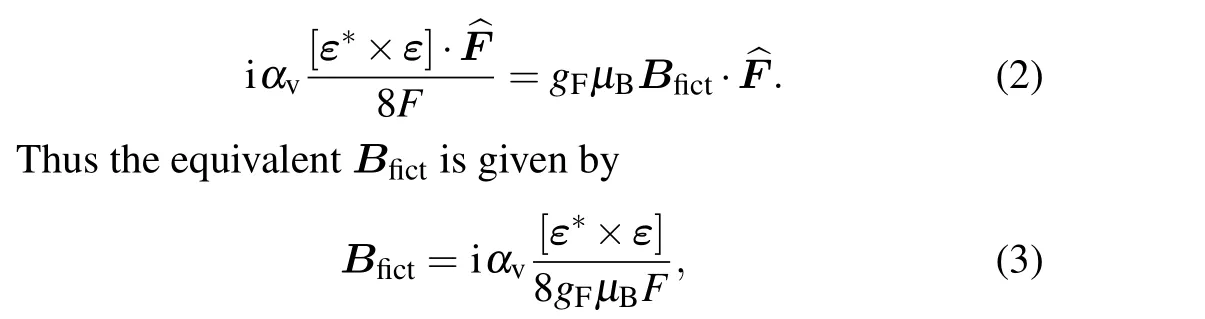
withµBas the Bohr magneton andgFas the hyperfine Lande factor.The direction of theBfictis determined by the light field vector i[ε*×ε],which is a real vector.Similar to a real magnetic field, theBfictflips under time reversal.The maximal magnitude of the term i[ε*×ε] is obtained with a fully circularly polarized ODT and is zero for a linearly polarized trapping field.It is convenient to express the shift in terms of the mean trap depth for ground states asUa=-1/4αs|ε|2.For the ground state of85Rb qubits in an 830 nm circularly polarized ODT,we calculateBfict=-0.10(1)(G/MHz)·Ua.
For an atom in the electronic ground state, the fictitious magnetic field behaves in almost every respect like a real magnetic field.When an atom is in the hybrid real–fictitious field,the total amplitude and direction of the field are under the rule of vector operation.Thus,theBfictcan be vector-added to the real magnetic fieldBreal,such that the atom is in total exposed to the effective magnetic fieldBeff=Bfict+Breal,which has been found in early works.[19,25,26,28,29]This was further supported in various experiments, demonstrating, for example,optically induced spin precession and echoes in an atomic beam,[20,21]an optical Stern–Gerlach effect from Zeeman-like ac Stark shift,[22,30]and an optically induced fictitious magnetic trap on an atom chip.[23]
In our experiment,we define the propagation direction of the circularly polarized trapping laser to beZ-axis, which is also the direction ofBfict.The axis of the Helmholtz coil producingBbiasis not perfectly aligned with the propagation direction of the trapping laser, as shown in Fig.1, so that the quantization axis created by theBbiasis not parallel to the trapping laser.Further adjustment of the quantization axis by the compensating magnetic fieldsBxandByin the other two directions orthogonal to theBbiasdirection created by compensating Helmholtz coils are required.Here, the three-axle magnetic fields created by the Helmholtz coils are collectively referred to as the external magnetic fieldBext.The total magnetic fieldBtotin a circularly polarized trapping light field is given by the expression
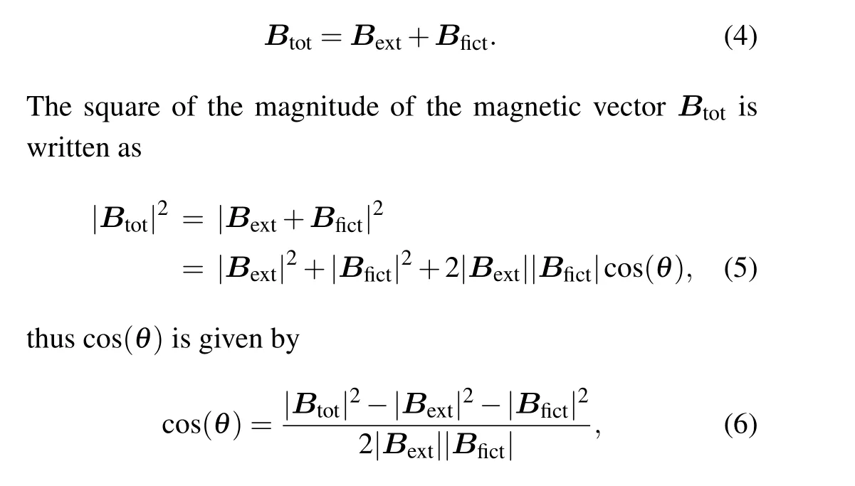
whereθis the angle between theBextandBfict, as shown in Fig.1.Thisθis exactly the angle between the quantization axis and the direction of the trapping laser.Whenϕ=0◦,the projection value ofθon theZ–Xplane is expressed asθx,which can be calibrated by theBx.Similarly,whenϕ=90◦,the projection value ofθon theZ–Yplane is expressed asθy,which can be calibrated by theBy.Equation (6) can be resolved into the following two parts with the parameters
For a given trap depth,theBfictis a constant.Therefore,the angle is stated as a function of theBextandBtot.Experimentally, the qubits serve as sensitive probes for measuring theBextandBtot, which are inherently dependent on the resonance frequencies of Zeeman-sensitive spectral transition.TheBext(Btot)can be accurately extracted from the measured resonance frequency of Zeeman-sensitive spectral transition in the linearly (fully circularly) polarized trap.Different values ofθx(θy)are obtained by varying theBx(By).The relationship betweenθx(θy)andBx(By)is quantitatively obtained.
3.Experimental setup
Figure 1 depicts the experimental setup and the spatial position of the magnetic fields.The trapping laser propagates alongkODT, the long axis of the ODT, which is set to be theZ-axis.In a circularly polarized ODT,thekODTis also the direction of theBfict.TheBext, making a polar angleθfrom theZ-axis and an azimuthal angleϕfrom theX-axis,is combined withBx,ByandBbiasfor shifting the atomic ensemble and defining the quantization axis.The projection value ofθonto theZ–X(Z–Y) plane is expressed asθx(θy) by settingϕ=0◦(90◦).Theθx(θy) can be calibrated by applying theBx(By), which is linear with the compensating Helmholtz coil currentXcurrent(Ycurrent).The85Rb qubits are rotated by microwave radiation, which is sent through a microwave antenna that is placed at a fixed distance of 4 cm away from the ODT.The experimental details on trapping and manipulating a single85Rb qubit have been described in our previous work.[18]In brief, the single atom for encoding quantum logical state is obtained by loading it into an 830 nm ODT directly from a magneto-optical trap(MOT)based on collisional blockade mechanism.[34,35]When a single atom is detected,it is further cooled to about 14µK with the standard optical molasses method in linearly polarized ODT with trap depth of 0.4 mK.We note that the polarization of the trapping laser is actively engineered by incorporating a liquid crystal retarder.Then the trapped atom is initialized into the hyperfine state of|0〉≡|5s1/2,F=2,mF=0〉 with optical pumping.For the state-selective detection after the manipulating, a circularly polarized probe laser beam resonant with the transition between|5s1/2,F=3〉and|5p3/2,F=4〉is applied to push out the atoms in the state|5s1/2,F=3〉.Whereas,the atoms in the state|5s1/2,F=2〉remain in the trap and contribute to the fluorescence, which is collected by a single-photon counting module.
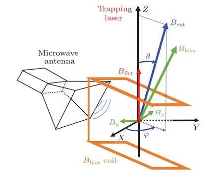
Fig.1.Experimental setup and spatial position of the magnetic fields.The 85Rb atom(red dot)is trapped in an 830 nm ODT and coherently manipulated with microwave radiation from a horn outside the vacuum cell.The bias magnetic field Bbias is created by a leaning Helmholtz coil.The compensating magnetic fields Bx and By are also created by Helmholtz coils, which are not shown here.The direction of the external magnetic field Bext (blue line) can point in any direction by changing the Bx and By.Note that the magnetic field values and the angle shown here are not strictly to scale.
4.Results and discussion
For our compensation experiment,each experimental sequence starts by loading atoms into the MOT and transferring them to the ODTs.Assuming that the trap depth is shallow,the effect ofBfictis not obvious.On the contrary, if the trap depth is deeper, the atoms in the ODTs experience a higher temperature, leading to an inhomogeneous light shift broadening of the microwave spectrum for a ground-state hyperfine transition.Therefore,the typical parameter for our trap depth ish×(-1.2 MHz).
Taking theBbiasto be about 0.60 G with a fixed Helmholtz coil current, we measure the dependence ofθxon the compensating Helmholtz coil currentXcurrent.Firstly,we set 40 mA forYcurrent, which is an estimated value forϕ=0◦,and measure the microwave resonant frequencies between Zeeman-sensitive hyperfine states|0〉and|5s1/2,F=3,mF=1〉 in linearly and circularly polarized ODTs.The microwave spectroscopy is driven by microwave radiation at varying frequencies around 3.036 GHz.With eight different values ofXcurrent, eight sets of microwave resonant frequencies are measured, as shown in Fig.2(a).Then, eight corresponding groups ofBext(Btot) in linearly (fully circularly)polarized ODTs, as shown in Fig.2(b), are extracted from the microwave resonant frequencies by using the Breit–Rabi formula(x=µ0B/∆EHFS))[36,37]for sublevels of the two hyperfine ground states.When the difference betweenBextandBtotreaches the maximum, theBextis parallel to the trapping laser.We obtain that theBfict=Btot-Bextis 0.12(2) G, which is consistent with the theoretical resultBfict=-0.10(1) (G/MHz)×Ua=0.12(1) G.Finally, substituting the fitted values ofBextandBtotunder the sameXcurrentinto Eq.(7) yields the dependence ofθxonXcurrent,which is shown in Fig.2(c) with purple squares.Theθxscales linearly with theXcurrent, and the fitted equation isθx=-0.20(1)(◦/mA)×Xcurrent+23(4)◦.According to this equation, we obtain that the calibrated value ofθxis 23(4)◦.WhenXcurrentis 115 mA,θxis compensated to 0(4)◦, which means that the quantization axis is parallel to the trapping laser.
Accordingly, setting 115 mA forXcurrent, seven sets of microwave resonant frequencies are measured, as shown in Fig.2(d).The fitted values ofBextandBtotunder the sameYcurrent, as shown in Fig.2(e), are collected in the same way as above.The maximum difference betweenBextandBtotis 0.12(0)G,which is also consistent with the theoretical result 0.12(1) G.Then, the dependence ofθyonYcurrent, which is shown in Fig.2(f)with pink circles,is obtained though Eq.(8).Theθyscales linearly withYcurrent, and the fitted equation isθy=-0.28(1)(◦/mA)×Ycurrent+9(2)◦.From this equation,we obtain that the originalθyis 9(2)◦.WhenYcurrentis 32 mA,θyis compensated to 0(4)◦.
In our experimental system, the calculated values ofθxandθyare 23(4)◦and 9(2)◦,respectively.With knownθx(θy),we can obtain the projection value of anyBbiasin the other two directions orthogonal to theBbiasdirection and eliminate theθx(θy) by applying the compensating magnetic fieldBx(By) in the equivalent direction.Naturally, the compensating currentXcurrent(Ycurrent)is obtained based on the linear relationship between the compensating magnetic fieldBx(By)and the compensating Helmholtz coil currentXcurrent(Ycurrent).In addition, an estimation of the angle between the other two compensating magnetic fieldsBxandByis(90±10)◦,which is obtained by comparing theBfictfrom Figs.2(b)and 2(e).
To understand the sources contributing to the aboveaccumulated error ofθx(θy), we examine four main sources of error during the measurement of the magnetic fields in our experiment.
(1)The temperature fluctuation of the atoms As a thermal ensemble with the temperature ofTa,the atoms possess an average potential energy of 3κBTa/2.The average trap depthUaseen by the thermal atoms fulfillsUa=hU0+3κBTa/2,whereU0is the dipole potential at the bottom of the trap.During the experimental sequence, the temperature with a fluctuation of 10% is obtained using the release and recapture method.It introduces a 3% fluctuation in theBfict, which is proportional to the trap depthUa.So the maximum fluctuation of the cos(θ)is 3%,which is the same order of magnitude as the calculated value ofθx(θy).
(2)Fluctuations in the background magnetic field Using a flux-gate magnetometer, we measured a peak-to-peak value of the magnetic field (with fluctuations of∼1.0 mG)dominated by components at 50 Hz.This fluctuation of the background magnetic field in all directions introduces 1%fluctuation ofBfictand 1‰fluctuation ofBext.These parameters introduce the maximal fluctuation of the cos(θ)up to 15‰.
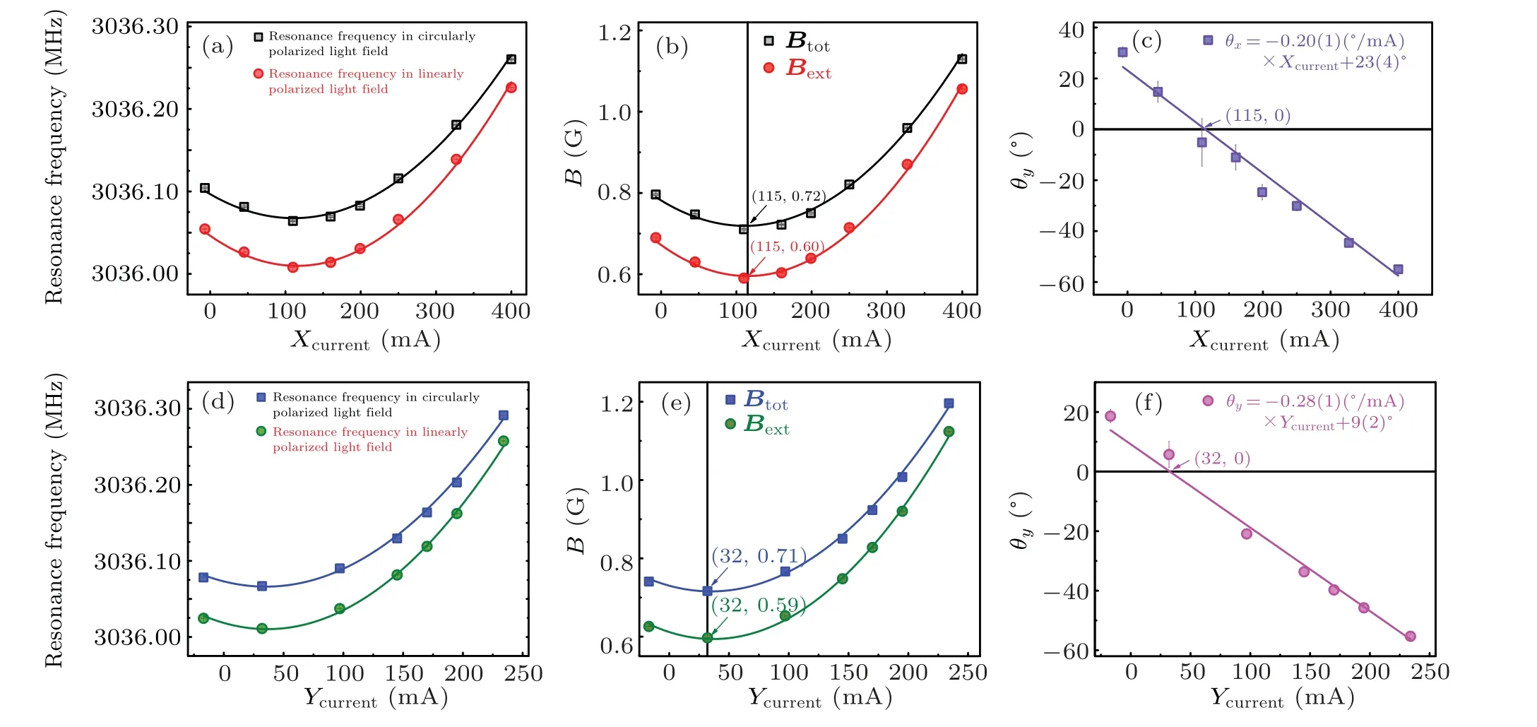
Fig.2.Dependence of magnetic field and angle on the other two compensating Helmholtz coil currents.(a) The dependence of microwave resonant frequencies in linearly polarized ODTs(red circles)and in fully circularly polarized ODTs(black squares)on Xcurrent.(b)The dependence of Bext (red circles)in linearly polarized ODTs and the Btot (black squares)in fully circularly polarized ODTs on Xcurrent.(c)The dependence of θx on Xcurrent.The purple squares are experimental data and the solid line is the fitting curve.(d)The dependence of microwave resonant frequencies in linearly polarized ODTs(green circles)and in fully circularly polarized ODTs(blue squares)on Ycurrent.(e)The dependence of Bext (green circles)in linearly polarized ODTs and the Btot (blue squares)in fully circularly polarized ODTs on Ycurrent.(f)The dependence of θy on Ycurrent.The pink circles are experimental data and the solid line is the fitting curve.The data points in these figures are averaged over 50 experimental runs.
(3)Error introduced by the technical limitations The currents of the three pairs of Helmholtz coils are actively locked by proportional integral and differential controllers with precise resistors(RS:VPR221T)which serve as feedback sensors.We monitor the current feedback loop that the current drifts by∼1‰.The contributions ofBxandByto the fluctuation ofBextare cos(90◦-θ)×∆Bxand cos(90◦-θ)×∆By,which are orders of magnitude smaller than the measurement error and nearly negligible.However,the contribution ofBbiasto the fluctuation ofBextis cos(θ)×∆Bbias,which is not negligible.Thus these parameters introduce the fluctuation of the cos(θ)up to 6‰.
(4)Fitting error of experimental data The inhomogeneous light shift broadening of the microwave spectrum frequency between states|0〉and|5s1/2,F=3,mF=1〉is 1‰,which is linear with Zeeman shiftgFµBmFB.Thus the fitting errors of theBextandBtotare 1‰and the fluctuation of cos(θ) is 6‰.All sources of errors combine to give a∼4%fluctuation of the compensated value ofθx(θy),consistent with the measurement result.
To further verify the differences between the calibrated and uncalibrated angles and the calibration accuracy of the compensating technique,we observe the Rabi oscillations between|0〉and|5s1/2,F=3,mF=0〉states of85Rb qubits in both the linearly and circularly polarized ODTs.Rabi oscillations on Zeeman-insensitive transition are recorded at a trap depth ofh×(-10.0 MHz).TheBfict=-0.10(1)(G/MHz)×Uais about 1.00 G, which is the same order of magnitude as theBext.We fit the experimental data in Fig.3(a) withP(t) =C[1-cos(ΩRt)]/2, which yields Rabi frequencies ofΩR/(2π)=7.2(1) kHz in a linearly polarized ODT andΩR/(2π) = 15.9(1) kHz in a circularly polarized ODT before implementing the compensating magnetic fields.Owing to theBfictinduced by the circularly polarized trapping laser,the direction of the quantization axis is different from that in the linearly polarized ODT.Consequently,the projection value of the microwave antenna on the quantization axis varies in ODTs with different polarizations,which leads to inconsistent Rabi frequencies.In addition, the dephasing of Rabi oscillation in circularly polarized ODTs is due to the impurity of the degree of trapping laser polarization, which is caused by the original angle between theBbiasand the propagating direction of the light field for trapping neutral atoms.After applying the compensating magnetic fields of theX- andY-axis withXcurrent=115 mA andYcurrent=32 mA,the Rabi frequency of the Zeeman-insensitive transition in circularly polarized ODTs is almost the same as that in linearly polarized ODTs,as verified by the experimental data in Fig.3(b);the Rabi frequencies are 5.4(2) kHz and 5.7(1) kHz, respectively.The maximum population detected in state|0〉is 90(5)%in Fig.3.This evident decrement,as observed from 100%,is caused by two reasons.One is that some atoms are lost before the state-selective detection due to atoms heating in the ODTs.The other reason is the imperfect optical pumping process.
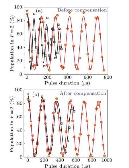
Fig.3.Rabi oscillations in linearly polarized ODTs(red dots)and circularly polarized ODTs (black squares) before and after implementing the compensating magnetic fields in the other two directions orthogonal to Bbias direction.(a)Before applying the compensating magnetic fields,the relative difference of Rabi frequencies in linearly and circularly polarized ODTs is 0.377(7)with θx =23(4)◦and θy =9(2)◦.In addition, the lifetime of the Rabi oscillation in linearly polarized ODTs is about 433µs.(b)After the compensation,the relative difference has been reduced to almost zero with θx =0(4)◦and θy=0(4)◦,which also substantially enhances the lifetime of the Rabi oscillation in linearly polarized ODT to 1464µs.The data points in this figure are averaged over 50 experimental runs.
5.Conclusion
In conclusion,we have presented a novelin situmethod to calibrate the angle between the quantization axis and the propagating direction of a tightly-focused trapping laser.With this method,the projected value of the angle on either of the compensating planes is reduced to 0(4)◦,which is very important for the accurate measurement of hyperpolarizability in magicintensity ODTs.Moreover,when the original angle is reduced to nearly zero, the projected value of the microwave power on the quantization axis is a constant, which is beneficial to the coherent manipulation of single qubits in magic-intensity ODT arrays.Our method can be straightforwardly extended to other similar precision measurements with trapped neutral atoms,e.g.,cancellation of the angle between circularly polarized Rydberg excitation lasers and the quantization axis.[38]
Acknowledgements
Project supported by the National Natural Science Foundation of China(Grant Nos.12104414,12122412,12104464,and 12104413) and the China Postdoctoral Science Foundation(Grant No.2021M702955).
猜你喜欢
Chinese Physics B(2023年12期)2023-12-15
小读者之友(2021年8期)2021-09-10
抗癌之窗(2021年3期)2021-02-12
歌海(2020年5期)2020-11-16
金山(2018年3期)2018-04-12
知音·上半月(2017年4期)2017-04-15
诗选刊(2015年4期)2015-10-26
人生与伴侣·共同关注(2015年31期)2015-05-30

- Chinese Physics B的其它文章
- Unconventional photon blockade in the two-photon Jaynes–Cummings model with two-frequency cavity drivings and atom driving
- Effective dynamics for a spin-1/2 particle constrained to a curved layer with inhomogeneous thickness
- Genuine entanglement under squeezed generalized amplitude damping channels with memory
- Quantum algorithm for minimum dominating set problem with circuit design
- Protected simultaneous quantum remote state preparation scheme by weak and reversal measurements in noisy environments
- Gray code based gradient-free optimization algorithm for parameterized quantum circuit