
Efficient loading of cesium atoms in a magnetic levitated dimple trap
2024-02-29 09:17GuoqingZhang张国庆GuoshengFeng冯国胜YuqingLi李玉清JizhouWu武寄洲andJieMa马杰
Chinese Physics B 2024年2期
Guoqing Zhang(张国庆), Guosheng Feng(冯国胜), Yuqing Li(李玉清),3,†,Jizhou Wu(武寄洲),3,‡, and Jie Ma(马杰),3
1State Key Laboratory of Quantum Optics and Quantum Optics Devices,Institute of Laser Spectroscopy,College of Physics and Electronics Engineering,Shanxi University,Taiyuan 030006,China
2Department of Magnetic Resonance Imaging,The First Hospital of Shanxi Medical University,Taiyuan 030006,China
3Collaborative Innovation Center of Extreme Optics,Shanxi University,Taiyuan 030006,China
Keywords: ultracold atom,magnetic levitation,dimple trap
1.Introduction
Remarkable advances in research of ultracold atoms and molecules are helpful for realization of the laser cooling neutral atoms.Especially, the observation of Bose–Einstein condensation (BEC) in magnetically or optically trapped atomic vapors of alkali metal has opened a new field of research at the intersection of atomic and condensed matter physics.[1–4]From now on, there exist over twenty alkali metal or alkaline earth atoms’ species of BECs obtained.The dimple trap of ultracold atoms,in which adiabatically changing the shape of a potential can locally increase the phase-space density of a trapped atomic gas,[4,5]is widely applied in realizing BEC of different atomic species, such as133Cs,[2]23Na,[6]and87Rb,[7]etc.Recently, it is of particular interest that the one-dimensional BECs by tight dimple potential have made significant progress[8]in quantum tweezers,[9,10]in controlling the interaction between dark solitons and sound,[11,12]and in introducing defects such as atomic quantum dots in optical lattices.[13]In addition, they also have the potential applications[14]in atom lasers,[15,16]atom interferometry,[17]ultra slow light propagation,[18]and analogs of cosmological physics.[19,20]
For realization of BEC of dilute atomic gases in an optical trap,evaporative cooling is often the most important stage.The cooling efficiency is defined as the ratio of the increase in phase space density to the decrease in the number of atoms remaining in the optical trap after evaporative cooling, thus a high phase space density without loss of atoms will lead to an effective evaporative cooling.Usually, the phase space density (Γ) in BECs is required to satisfy the condition ofΓ=nλ3dB=1.202, wherenis the peak number density of a classical gas andλdBis the thermal de Broglie wavelength.[21]The dimple trap, which can be applied to increase the phase space density by modifying the shape of the trapping potentials, was first demonstrated theoretically by Pinkseet al.,[4]and then applied in an experiment for the cesium BEC.[2]The maximum phase space density can be up to more than a factor of 100.[22]Effectively evaporative cooling requires elastic collisions, but the inelastic collisions in many atomic species are avoided less, such as133Cs and85Rb,[21]the two-body and three-body loss is a huge challenge in the related ultracold atomic and molecular experiments.As a result,the quantum degeneracy gas requires a complicated evaporation strategy and induces a small number of the final atoms.Very recently, a noble method was proposed to obtain BEC without evaporative cooling.[23–25]
Over the past decade, many theoretical and experimental kinds of research were based on the dimple trap.However, detailed experimental studies of the effect of magnetic fields on the number of loading and trapping atoms are still lacking.[26–28]The dynamic evolution and quantitative theoretical analysis have not yet been thoroughly understood and studied.Therefore, more precise studies are necessary to determine the effect of magnetic fields on the number of atoms loaded and trapped in dimple traps.[29,30]
In this paper, the loading of cold atoms in a dimple trap is studied in detail.The theoretical loading potentials of various magnetic field gradients and bias fields are presented.The number of trapped atoms under various magnetic gradients and bias fields is measured and the dependence between them is given.The results are in good agreement with the theory.
2.Experimental setup
We start with ultracold133Cs atoms in a vapor vacuumloaded magneto-optical trap(MOT)at a background pressure of 3×10⁻⁸Pa.The experimental setup is shown in Fig.1(a).Following the achievement ofµmust be inside math mod a compressed MOT and optical molasses,3×107atoms are obtained with a peak density of∼1011cm-3.Then, the atoms are transferred to a three-dimensional optical lattice, and degenerated Raman sideband cooling(DRSC)is applied to cool the atoms to a low temperature of∼1.7 µK and to polarize them in the desiredF=3,mF=3 states.A red far-off resonance optical dipole trap, which consists of two crossing laser beams with an angle of 90◦, is employed to load the atoms.The powers for the two laser beams of the crossed dipole trap are 7.0 W and 7.2 W,and the corresponding beam waists are 230µm and 240µm at the trap center,respectively.We used two red long-range resonant lasers (same as dipole lasers)to form the dimple trap generated by a 1070-nm,multifrequency, linearly polarized fiber laser (IPG Photonics), the corresponding beam waists are 45 µm and 43 µm, respectively, crossing horizontally at an angle of 30◦.Switching of the beams is done by external acoustic-optical modulators,dimple 1 is downshifted in frequency by 90 MHz, whereas dimple 2 is upshifted by 90 MHz to prevent any interference.
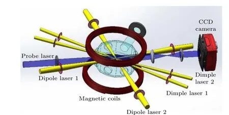
Fig.1.Experimental setup.Dipole lasers 1 and 2 are applied to construct the crossed dipole trap.Dimple lasers 1 and 2 are applied to implement the dimple trap.Magnetic coils are used to produce the magnetic-field gradients and bias field.The probe laser passes through the trapped atoms, and the number and density of atoms are measured using the absorption image.
3.Experimental results and analysis
Figures 2(a) and 2(b) show the absorption image taken in the horizontal direction after 3 ms of expansion from the dimple trap, the corresponding distribution of optical density along the horizontal direction is shown in Figs.2(c)and 2(d).Here the measured atomic number is about 3.8×10⁶of the dimple trap,which is nearly equal to 3.67×10⁶of the dipole trap, while the optical density of atoms in the dimple trap is large than the dipole trap.Figure 2(e)shows the atomic density in the dimple trap of signal laser beam and double laser beams.The atomic density for the double laser is larger than that for the signal laser at the same laser intensity.This difference is mainly attributed to the different dimple trap potentials, which are double laser potentials larger than the signal laser.The atomic density is strongly dependent on the laser intensity and continuously increases with the laser intensity.The observed atomic density varies from 0.364×1011cm-3to 1.759×1011cm-3(from 0.291×1011cm-3to 1.041×1011cm-3)for double laser(signal laser)when the laser intensity increases from 0 to 3×10⁻⁴cm-2.The errors are mainly from the systematic uncertainty induced by the fluctuation of the number of trapped atoms in each experimental cycle, the error in determining the resonance frequency, and the fitting error.The maximum atomic density is increased up to a factor of∼4.8 compared to that atomic density in the dipole trap.Thus the atomic density of ultracold133Cs atoms can be enhanced by using a dimple trap.
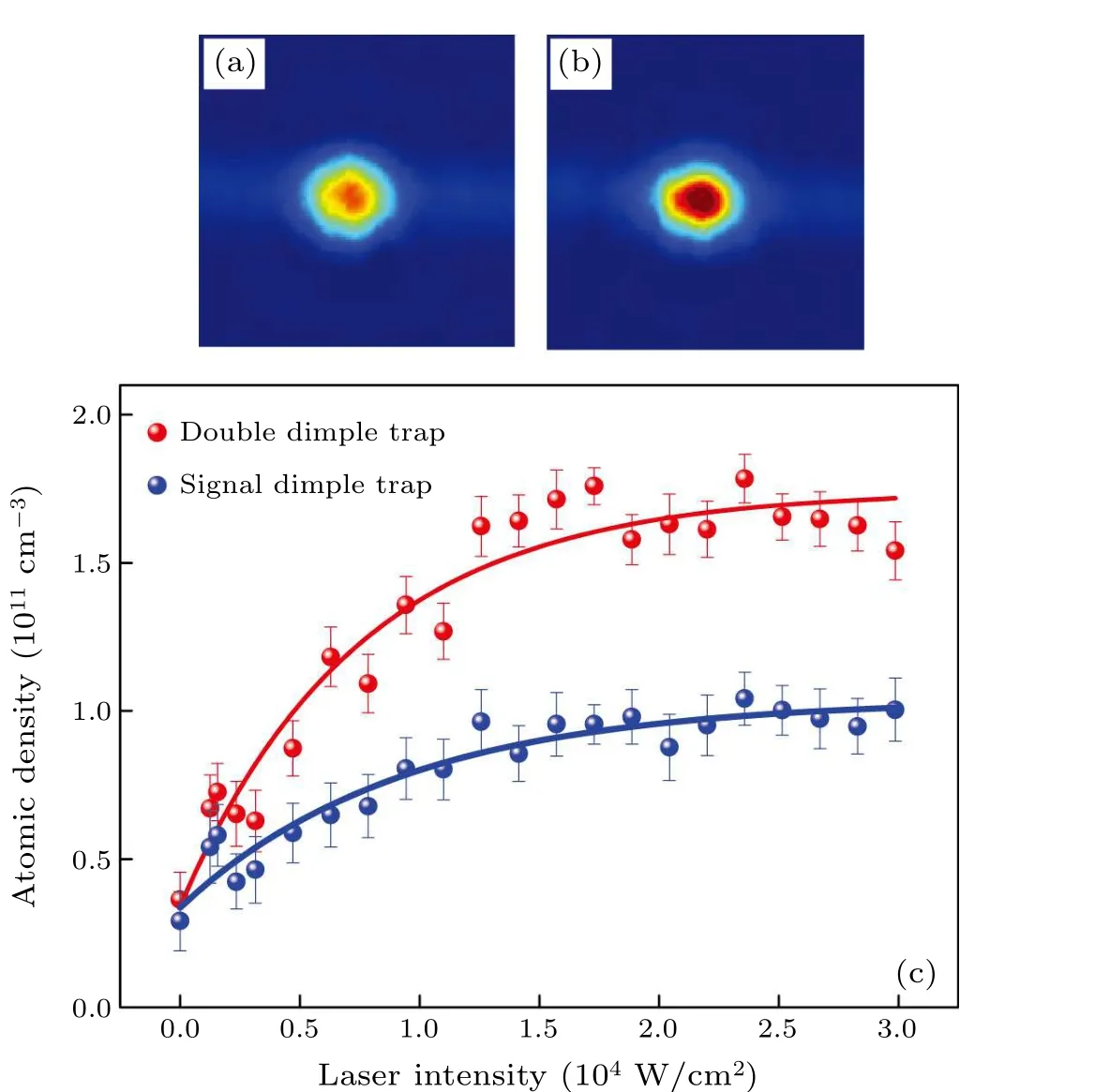
Fig.2.[(a),(b)]Absorption images that represent horizontal shots taken after 3 ms of expansion in the dipole trap and dimple trap,respectively.The corresponding distribution of optical density along the horizontal direction is shown in (c) and (d).(e) Atomic density as a function of laser intensity for the signal laser and double laser.The dots are experimental data.The solid lines are the fits using the exponential function.
Now we give a simple discussion of the loading potential of a typical crossed dimple trap.A Gaussian laser beam induces a trapping potential that is proportional to laser intensity and can be expressed as
wherecis the speed of light,Γthe natural line width,ωthe laser frequency,an effective transition frequency defined by a weighted average of both D lines forcesium atoms,Pthe total laser power,xthe axial coordinate along the beam axis,rthe radial coordinate, andw(x) the laser beam waist.For the dimple trap, the potential is formed by adding two small waist Gaussian laser beams.Considering the magnetically levitated dipole trap,the total vertical potential contains the gravitational force and the magnetic force due to magnetic field gradients,given as
whereU1,U2,U3,andU4represent the potentials of two dipole lasers and two dimple lasers,gis the acceleration due to gravity,µBis the Bohr magneton,gFis the Land´e factor,and∂B/∂zdenotes the magnetic field gradient.The effect of magnetic field gradient on the total potential in the vertical direction is depicted in Fig.3 in accordance with Eq.(2).The destructive potential is so great when the magnetic field gradient is equal to zero, as shown in Fig.3(a), that there is no practical potential to trap atoms.Figure 3(b)depicts the total potential at a magnetic field gradient of 27 G/cm.Figure 3(c) illustrates the theoretical magnetic field gradient required to completely offset the destructive potential brought on by gravity.The destruction potential will reappear if the magnetic field gradient is further increased,as shown in Fig.3(d).
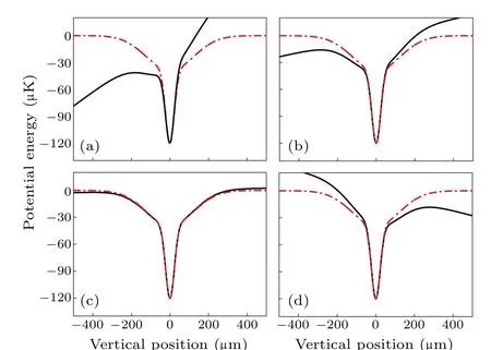
Fig.3.Potentials of the dimple trap in the vertical direction at 0 G/cm(a), 27 G/cm (b), 40.2 G/cm (c), and 47 G/cm (d) magnetic field gradients.The dipole trap potential is shown as a red dashed line, and the total potential consisting of both the dipole trap potential and the destructive potential caused by the 133Cs atoms’ gravitational pull is shown as a black solid.
The gradient of the vertical magnetic field applied to account for the destructive potential,which leads to a horizontal magnetic field∂Bx/∂x=∂By/∂y=(2/3)mg/µBin the case of cylindrical symmetry,is an antitrapping potential in the horizontal direction,to eliminate this antitrapping potential,a bias fieldBbiasmust be applied in the vertical direction.By combining the anti-trapping magnetic potential and the optical potential,the total potential can be given as
whereU0(x,y, 0) is the optical potentials of the dipole laser and dimple laser,xandyare the axial coordinates perpendicular to the beam axis.Figure 4 shows the potential of the dimple trap in the horizontal position with the magnetic field gradients and bias fields.When the bias field is zero, as shown in Fig.4(a) the anti-trapping potential is not an effective potential for trap atoms, when the bias field is 12 G, as shown in Fig.4(b)the anti-trapping potential is completely canceled out and the total potential is nearly equal to the dimple trap potential in the horizontal direction.With the further increase of the bias field, the anti-trapping potential will be close to infinitesimal,but not zero according to Eq.(3).
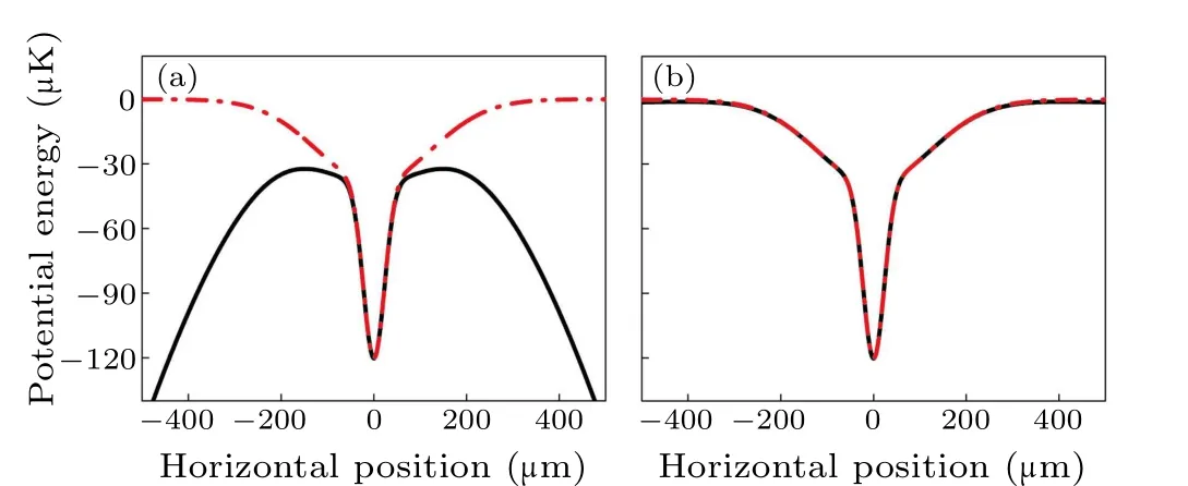
Fig.4.Potentials of the dimple trap at bias fields of 0(a)and 12 G(b)in the horizontal direction.The total potential is represented by the black solid line, while the potential of the dimple trap is represented by the red dashed line.
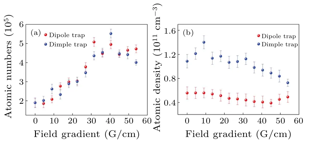
Fig.5.The quantity(a)and density(b)of atoms in the dipole trap and dimple trap versus the magnetic field gradient.
Based on the above theoretical analysis,we examined the correlation between the amount of atoms ensnared in the dimple trap and the magnetic field gradient with a bias field of 12 G, as suggested by the above theoretical analysis.The atomic number was measured after loading 50 ms from the DRSC.Figure 5 shows the atomic numbers and density depending on the dipole trap and dimple trap on themagnetic field gradient.As the magnetic field gradient rises, the number of atoms in both dipole and dimple traps increases linearly.At the beginning, with the increase of the magnetic field gradient, the number of atoms in the dipole trap and the dimple trap increases linearly, and when the magnetic field gradient reaches 31.1 G/cm,the number of atoms in the dipole well decreases with the further increase of the magnetic field gradient.Since the atoms in the dimple trap have the same trend,the different peak value is 41.1 G/cm.It can be understood that the change in the shape of the optical trap influences the loading of the trapped atoms.For the density of the atoms, the rapid decrease from about 10 G/cm in the dimple trap is comparable with the slow trend of the dipole trap.These results are mainly due to the influence of magnetic field gradient on the volume of the optical trap.
To investigate the effect of the horizontal reverse trapped potential caused by the magnetic field gradient on the number of atoms loaded and trapped in the dimple trap, the magnetic field gradient is fixed at 40.2 G/cm to fully compensate for gravity.The dependence of the number of atoms trapped in the dimple trap on the bias field has been studied,as shown in Fig.6.The number of atoms is measured after 50 ms loading from the DRSC.In the initial phase,as the bias field increases,the atomic number in the dipole trap and dimple trap has a large growth rate.However,when the bias field reaches 15 G,the growth rate becomes very low.When the bias field approaches 30 G,the atomic number stops increasing.The density of the atoms in the dipole has a slowly increasing trend when a slowly decreasing trend is accrued in the dimple trap.For each data point, all initial parameters of atomic samples prepared by 3D DRSC, magnetic levitation dipole traps, and atomic samples prepared by magnetic levitation dimple traps remains unchanged during each experimental cycle except for the magnetic field gradient and bias field in Figs.5 and 6.
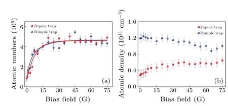
Fig.6.Atomic number(a)and density(b)in the dipole trap and dimple trap versus the bias field.The exponential function’s fits are represented by the solid lines.
We also measured the number and density of atoms in the dipole trap and dimple trap as a function of storage time, as shown in Fig.7.The atoms in the different traps have a marked decrease in the initial 150 ms of evaporation has been noticed,with a nearly uniform trend.This is mainly due to a powerful three-body recombination loss.In Fig.7(b), at the beginning of 150 ms, the density of atoms in the dimple trap presents a linear growth, then a nearly linear decrease with a long storage time.Compared to the dipole trap,the density of atoms is almost invariable with the time increase except tilted slightly to the downside.As we finishing the current work, we have recalled the earlier accomplishment of the similar works using magnetic field regulation or other efficient mechanisms from groups of Grimm and Chin.Weberet al.realized133Cs BEC in a magnetic levitated dimple trap for the first time by adjusting the external magnetic field and evaporating cooling in an optical potential trap.[31]Based on an improved trap loading and evaporation scheme, Kaemeret al.realized the atomic number of 105in the condensed phase.To test the tunability of the interaction in the condensate,the expansion of condensates is studied as a function of scattering length.[32]Detailed experimental results are demonstrated in Table 1.Compared to the previous achievements, the loaded133Cs number and density in our scheme have a good improvement.
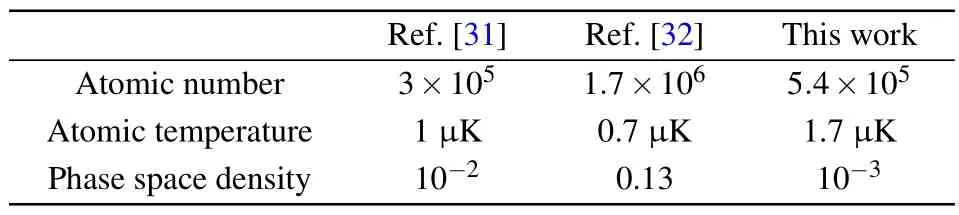
Table 1.Comparison of atomic loading.
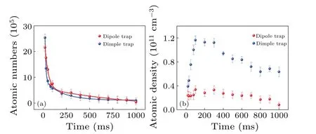
Fig.7.Atoms still present in the dipole trap and the dimple trap, as measured by their number (a) and density (b), as a function of time.The exponential function’s fits are represented by the solid lines.
4.Conclusion
We have carefully examined the loading of cold Cs atoms into a magnetically levitated dipole trap-based dimple trap.When compared to the dipole trap, the atomic density in the dimple trap has increased significantly.The number of trapped atoms is found to depend differently from atomic density on the magnetic field gradient and bias field.The sample theoretical analysis has explained the experimental result qualitatively.The dimple trap in the external magnetic field is expected to increase the atomic density for further validation of the quantum kinetic model of condensate formation.
Acknowledgments
This work was financially supported by the National Natural Science Foundation of China (Grant Nos.62020106014,62175140, 12034012, and 92165106), and the Natural Science Young Foundation of Shanxi Province (Grant No.202203021212376).
- Chinese Physics B的其它文章
- Unconventional photon blockade in the two-photon Jaynes–Cummings model with two-frequency cavity drivings and atom driving
- Effective dynamics for a spin-1/2 particle constrained to a curved layer with inhomogeneous thickness
- Genuine entanglement under squeezed generalized amplitude damping channels with memory
- Quantum algorithm for minimum dominating set problem with circuit design
- Protected simultaneous quantum remote state preparation scheme by weak and reversal measurements in noisy environments
- Gray code based gradient-free optimization algorithm for parameterized quantum circuit