
Design and fabrication of compound varifocal lens driven by polydimethylsiloxane film elastic deformation
2024-02-29 09:17WenHaoMiao缪文浩ZeFengHan韩泽峰RuiZhao赵瑞ZhongChengLiang梁忠诚SongFengKou寇松峰andRongQingXu徐荣青
Chinese Physics B 2024年2期
Wen-Hao Miao(缪文浩), Ze-Feng Han(韩泽峰), Rui Zhao(赵瑞),†, Zhong-Cheng Liang(梁忠诚),Song-Feng Kou(寇松峰), and Rong-Qing Xu(徐荣青)
1Center of Optofluidic Technology,College of Optoelectronic Engineering,Nanjing University of Posts and Telecommunications,Nanjing 210023,China
2Astronomical Observatories/Nanjing Institute of Astronomical Optics&Technology,Chinese Academy of Sciences(CAS),Nanjing 210042,China
3CAS Key Laboratory of Astronomical Optics&Technology,Nanjing Institute of Astronomical Optics&Technology,Nanjing 210042,China
Keywords: compound varifocal lens, PDMS film, elastic deformation, focal length, electromagnetic force,zoom ability
1.Introduction
Varifocal lens plays an important role in optical imaging, optical communication, bionic optics, medicine, micromanufacturing,optical scanning,etc.[1–7]In the traditional optical imaging system,the movable lens is moved by the moveable mechanical equipment, i.e., stepper motors to image objects at different locations, and consequently the focal length of the optical system is changed.[8–11]However, these lenses mentioned above have problems such as complex structures,bulky volume, mechanical movement, easily worn, seriously limiting its scope of application and fields.[12,13]
In recent years,the varifocal lens controlled by magnetic field or electric field has received much attention.The surface shape of varifocal lens is changed by applying pressure to realize zooming,and the commonly used filling material is generally transparent liquid.[14–20]In 2012, Li and Jiang proposed an electrowetting-based variable-focus lens, whose focal length changes from-15 mm to 28 mm.[21]In 2015, Ohet al.reported an electromagnetic driving liquid lens, whose focal length changes from-10 mm to 10 mm.[22]In 2018,Liet al.demonstrated an electrowetting-based focal-tunable lens,which reaches∼1.31 zoom ratio.[23]In 2019, Van Grinsvenet al.presented a liquid lens actuated by the Lorentz force,whose corresponding focal length can vary with the working current.[24]In 2020, Jamaliet al.developed a liquid crystal lens for presbyopia correction, and its diopter successfully changes from 1.5 D to 0 D.[25]These electrically or magnetically actuated variable focus liquid lens have advantages of no mechanical movement, simple structure, low cost, and high compatibility.[21–25]However, these liquid-filled lenses are prone to leakage,evaporation and fluidity,resulting in unstable lens performance.A nonmechanical varifocal lens with better stability,fast response,high modulation accuracy is urgently desirable for high-performance optical systems.
In this work, a varifocal compound lens driven by the(PDMS) film elastic deformation is designed and fabricated.It mainly consists of PDMS elastic film, PDMS lens, planeconcave lens, driving coil and annular magnet.The annular magnet surrounding the PDMS lens is fixed on the elastic film,while the plane-concave lens equipped with driving coils is installed directly above the PDMS lens to form a compound lens system.When different currents are applied,the electromagnetic force generated by the driving coil drives the annular magnet to move along the optical axis, which leads to elastic deformation of the PDMS film and further drives the PDMS lens to move axially.Since the distance between the PDMS lens and plane-concave lens changes, the focal length of the compound lens system changes as well.We depict the compound lens working mechanism and analyze its zoom ability in detail.When the current ranges from-0.20 A to 0.21 A,the focal length of the compound lens changes from 29.82 mm to 39.10 mm,and its relative focal length modulation achieves about 9.28 mm.According to experimental results, our compound lens exerts the zoom ability of varifocal optical system.The zoom ability of the compound lens can be further improved by optimizing the structure design.
2.Design and manufacture
2.1.Structure design
The schematic exploded diagram of our PDMS compound lens is depicted in Fig.1, where a PDMS lens and a plane-concave lens form a compound lens system.The plane-concave lens is embedded into an inner cavity of the first support frame, then a toroidal copper coil is mounted on the upper surface of the first support frame.The PDMS lens is attached in the center hole of an elastic film, and a ring-type neodymium magnet surrounding the PDMS lens is fixed on the elastic film.The elastic film ring is bonded to the second ring support while its other side is adhered to the bottom cavity.Finally,an upper cover is employed to encapsulate the system,and the aperture diameter of the upper cover is somewhat larger than that of the plane-concave lens.To maintain a high axiality,it is necessary to make sure that the planeconcave lens and the PDMS lens have the same center symmetrical axes.
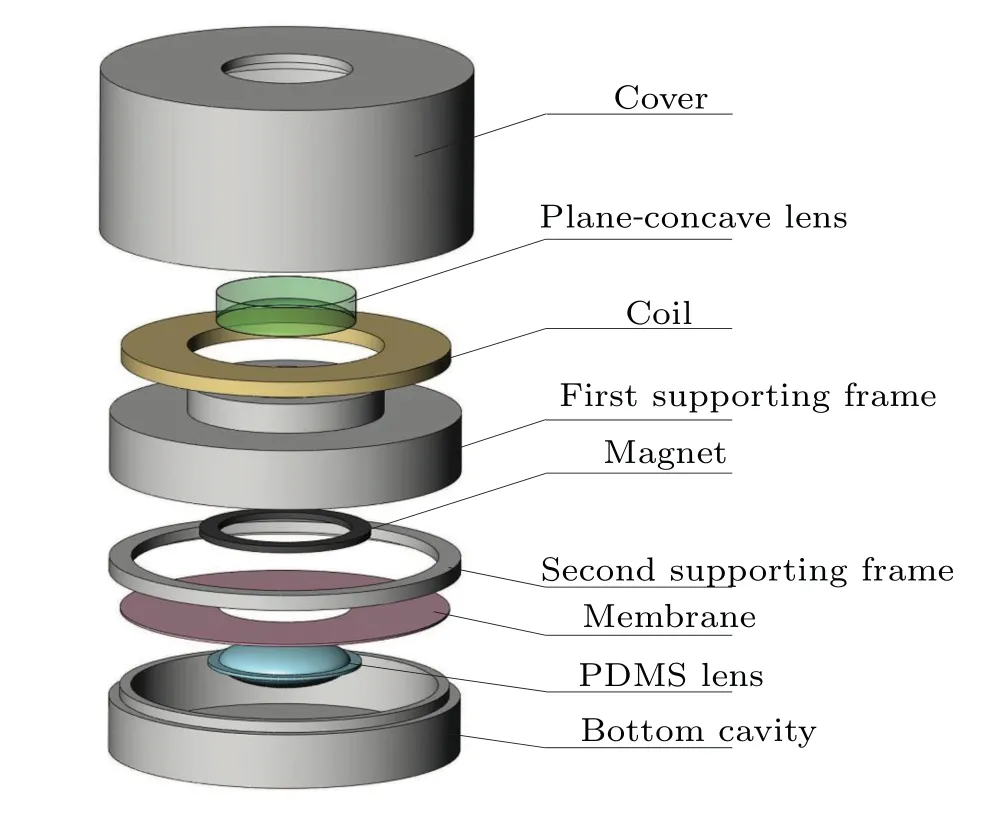
Fig.1.Schematic diagram of exploded diagram of varifocal compound lens.
2.2.Working principle
The working mechanism of the proposed compound lens is depicted in Fig.2.In this work, the current in the driving coil is assumed to be forward when the magnet receives an upward electromagnetic force.When the electromagnetic force is downward, the current in the driving coils is defined as reverse current.
In Fig.2(a),the current in the driving coils is zero corresponding to the initial state of the compound lens.
In Fig.2(b), the elastic film deforms upward, resulting in the longitudinal movement of PDMS lens when an upward electromagnetic force is loaded on the magnet.Since the distance between the PDMS lens and plane-concave lens decreases, the focal length of our compound lens tends to increase.
Similarly, when reverse current is applied to the drive coils,the magnet receives a downward electromagnetic force,thus the PDMS lens following the magnet is downward.Consequently, the distance between the PDMS lens and planeconcave lens increases, making the focal length of the compound lens smaller as shown in Fig.2(c).
According to the geometric optics theory,the focal length of our proposed compound lens system can be given as[26]
wheref1is the focal length of the plane-concave lens,f2is the focal length of the PDMS lens,anddis the distance between the optical centers of the two lenses.
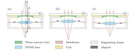
Fig.2.Working principle diagram of compound lens in(a)initial state,(b)operating state at forward current,and(c)operating state at reverse current.
2.3.Device fabrication
In this work,the upper cover,bottom cavity,the first and second supporting frames are printed by three-dimensional(3D) epoxy material.A circular PDMS film with a central hole(11.7 mm in diameter)is used as the elastic film, whose diameter is 30 mm and Young’s modulus is about 1.7.Here,the PDMS film connects PDMS lens (∼0.7 g) and magnet(∼0.9 g) together by the PDMS prepolymer (ratio 10:1).In order to facilitate passage and observation of light,high transparency materials are used.
The fabrication processes of our compound lens are generally described as follows:the first step is to embed the planeconcave lens(-25 mm in focal length,12.7 mm in diameter)into the inner cavity of the first support frame,and then place a toroidal copper coil on the first support frame, and the second step is to fabricate the PDMS lens,whose detailed process is summarized as follows.First,a chemical mixture(Sylgard 184 silicone elastomer base and curing agent at a radio of 10:1)is evacuated in a vacuum pump until no bubbles appears;then,the degassed mixture is poured into a prepared mold(diameter 11.7 mm and thickness 4.8 mm in the middle part, thickness 0.5 mm in the edge parts,width 1.5 mm)and cured in the baking oven at 55◦C.After drying , the PDMS lens is carefully removed from the mold,which is strong enough to be detached from the mold and touched by tweezers.To smooth the surfaces of the PDMS lens,PDMS prepolymer is spin-coated on the lens by a spin coater (low speed 800, high speed 1000);finally, the PDMS lens is baked in the baking oven at 80◦C for 40 min.
The PDMS prepolymer (ratio 10:1) is coated on the brim of the PDMS lens to join the PDMS lens and elastic film together.Similarly, the annular magnet (inner diameter 12.2 mm, outer diameter 15.6 mm, NdFeB, 1970 Gs,1 Gs=10-4T) surrounding the PDMS lens is stuck on the elastic film by the PDMS prepolymer,and the bonded PDMS lens component is put into baking oven and treated at 70◦C for 1.5 h.
The elastic film equipped with PDMS lens and annular magnet is fixed between the second ring support and the bottom annular cavity.
The PDMS lens component and the plane-concave lens component are combined together to form a coaxial compound lens.
Finally, the compound lens is encapsulated by an upper cover.To avoid the influence of external electromagnetic interference,an additional magnetism-insulator shell can be used to make an effective magnetic shield of the proposed compound lens.
3.Results and discussion
The schematic diagram of experimental setup is shown in Fig.3.The setup consists of a bottom light source, DC voltage with a current stabilizer control unit,our compound lens,and charged coupled device(CCD)camera and personal computer.A USAF resolution target is imaged by our compound lens and then recorded by a CCD camera.
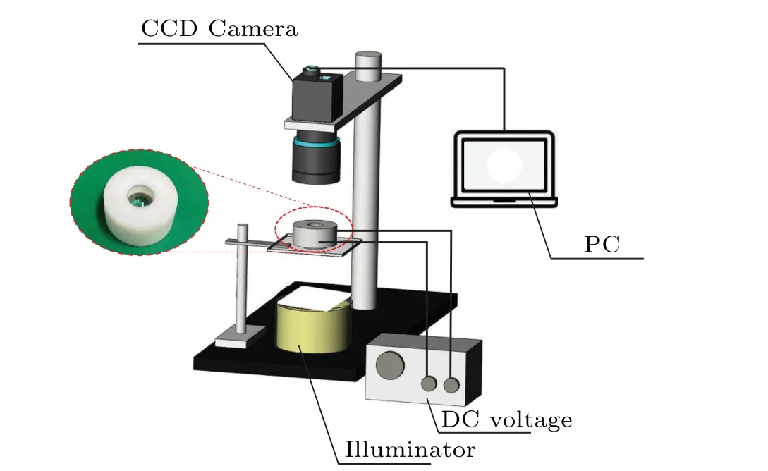
Fig.3.Schematic diagram of the experimental setup.
Figure 4 describes the imaging ability of our compound lens at different currents.In Fig.4(c), the photo is imaged in the focal plane of the compound lens corresponding to zero current.Modulate the working current from-0.2 A to 0.21 A,the image magnification as well as the focal length of our compound lens tends to increase gradually with the currents.Its relative change of image magnification is about 1.25.Once the current is removed, the compound lens will recover to its original state.
From Figs.4(c)to 4(a),we can find that when the reverse current is in the range from 0 A to-0.20 A,the line of element 4 in group 5 changes from clear at first to fuzzy when reverse current ranges from 0 A to-0.20 A.Similarly,when the forward current ranges from 0 A to 0.21 A,the image of pattern at element 1 of group 5 in resolution chart is getting fuzzy as shown in Figs.4(c)–4(f).It indicates that our compound lens has zoom ability and imaging ability.Finite change in imaging definition,the authors think,is attributed to limited movement distance of PDMS lens.By choosing high elastic film and optimizing device structure,the zoom ability and imaging ability of our compound lens can be improved significantly.
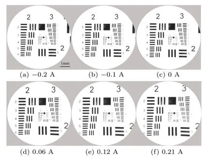
Fig.4.Photos imaged by compound lens at different currents.
Figure 5 shows focusing ability of the compound lens to distinguish between two objects positioned at different distances,where letters“N”and“J”are located 9 mm and 5 mm away from the proposed compound lens, respectively.When-0.2 A is applied to the driving coil,letter“J”is just focused shown in Fig.5(a),while the letter“N”achieves focusing effect shown in Fig.5(b)as the current is increased up to 0.18 A.The response time of the proposed compound lens is about 45 ms.The experimental results indicate that our proposed compound lens has excellent focusing ability.
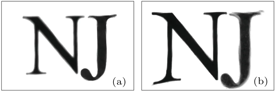
Fig.5.Focusing ability test of compound lens by using letters“N”and“J”located at different distances, showing (a) I =-0.2 A focusing letter “J”and(b)I=0.18 A focusing“N”.
When it works in a vibration environment,the PDMS lens will jump up and down,while the annular magnet fixed on the diaphragm will aggravate the displacement of PDMS lens.By optimizing the structural design and choosing the best elastic film, the proposed compound lens will possess certain antivibration ability and stability.Additionally, the spring plates can be added to absorb and buffer external shock.

Fig.6.Longitudinal displacement of PDMS lens versus applied current.
Figure 6 shows the longitudinal displacement versus the applied current for the PDMS lens driven by the electromagnetic force.Here the initial displacement of the PDMS lens is set to be zero when the current is zero.When the forward current ranges from 0 A to 0.21 A,the displacement of the PDMS lens increases with the working current increasing,whose increment reaches 2.74 mm.When the reverse current is applied to the driving coils,the displacement of the PDMS lens changes slowly and its displacement variation is only 0.9 mm.The displacement increment of the PDMS lens in the forward current is larger than that in the reverse current,and the authors suggest that this might be because the distance between magnet and driving coil produces significant effects on the electromagnetic force.
Figure 7 illustrates the variation of focal length with applied current for our compound lens.In this work, the initial distance between the PDMS lens and the plane-concave lens is about 7.7 mm,their corresponding focal lengths are 18.3 mm and-25 mm,so the initial focal length of the compound lens is 31.62 mm.From Fig.7 it can follow that the focal length increases from 31.62 mm to 39.10 mm when forward current ranges from 0 A to 0.21 A, while the focal length decreases from 31.62 mm to 29.82 mm as the reverse current changes from 0 A to-0.20 A.

Fig.7.Variation of focal length with applied current.
4.Conclusions
In this work, a varifocal compound lens is designed and fabricated.It mainly composed of PDMS lens,plane-concave lens, elastic membrane, driving coils, annular magnet, where PDMS lens and plane-concave lens form a compound lens system, the elastic membrane serves as the driving component.When different currents are applied to the driving coils, the annular magnet moves upward or downward, resulting in the elastic deformation of the PDMS film and then the longitudinal movement of PDMS lens.Due to the change of the distance between the PDMS lens and plane-concave lens, the compound lens exerts the zoom ability.The relative focal length varies from 29.82 mm to 39.10 mm when the current is in the range from-0.2 A to 0.21 A.
- Chinese Physics B的其它文章
- Unconventional photon blockade in the two-photon Jaynes–Cummings model with two-frequency cavity drivings and atom driving
- Effective dynamics for a spin-1/2 particle constrained to a curved layer with inhomogeneous thickness
- Genuine entanglement under squeezed generalized amplitude damping channels with memory
- Quantum algorithm for minimum dominating set problem with circuit design
- Protected simultaneous quantum remote state preparation scheme by weak and reversal measurements in noisy environments
- Gray code based gradient-free optimization algorithm for parameterized quantum circuit