
Coherent optical frequency transfer via 972-km fiber link
2024-02-29 09:17XueDeng邓雪XiangZhang张翔QiZang臧琦DongDongJiao焦东东DanWang王丹JieLiu刘杰JingGao高静GuanJunXu许冠军RuiFangDong董瑞芳TaoLiu刘涛andShouGangZhang张首刚
Chinese Physics B 2024年2期
Xue Deng(邓雪), Xiang Zhang(张翔), Qi Zang(臧琦), Dong-Dong Jiao(焦东东),Dan Wang(王丹), Jie Liu(刘杰), Jing Gao(高静), Guan-Jun Xu(许冠军),†,Rui-Fang Dong(董瑞芳),‡, Tao Liu(刘涛),§, and Shou-Gang Zhang(张首刚)
1National Time Service Centre,Chinese Academy of Sciences,Xi’an 710600,China
2Key Laboratory of Time Reference and Application,Chinese Academy of Sciences,Xi’an 710600,China
3School of Communications and Information Engineering and School of Artificial Intelligence,Xi’an University of Posts and Telecommunications,Xi’an 710121,China
Keywords: optical frequency transfer,fiber link,phase noise cancellation
1.Introduction
The development of optical clocks urgently needs highprecision optical frequency transfer, which plays an important role in various scientific applications.[1–5]Fiber links have shown great performance in optical frequency distribution with instability at 10-20level for hundreds or even thousands of kilometers,[6–8]enabling numerous scientific researches such as atomic clock comparison, fundamental physics,geodesy,and astronomy.[5,9–11]In 2022,the comparison of two transnational ultra-stable lasers was demonstrated based on coherent optical frequency transmission.Two links added a total distance of 2220 km, allowing the lasers to be transferred to an intermediate node for comparison.[11]Utilizing fiber links for optical frequency dissemination offers advantages such as low loss at communication channels, immunity to electromagnetic interference,and access to a global telecommunication network.However, a challenge of optical frequency transmission through fiber is the inherent Doppler frequency shift,which is caused by the change of fiber length and refractive index introduced by environmental disturbances(such as temperature changes and vibrations), which will reduce the stability and accuracy of the transferred signal.[12,13]A phase locking loop(PLL)is typically used in the system to actively reduce Doppler noise by applying a fiber interferometer configuration to detect and compensate for round-trip phase noise of the link.[14–17]Nevertheless,the propagation delay of the signal constrains the feedback bandwidth and noise cancellation.Particularly, for long-distance noisy fiber links, the phase noise is substantial and variable,and the signal-to-noise ratio(SNR)is greatly worsened due to power attenuation,amplifier noises and fiber nonlinear effects.As the phase noise detection is obtained by the demodulation of round-trip beatnote after signal amplification, filtering, and frequency dividing, and all these signal processing units require an SNR not less than 20 dB–30 dB.Therefore, a poor SNR could lead to inaccurate phase detection, which in turn leads to sudden interruption of PLL and limits the long-term performance of transmission system.As an alternative approach,passive phase correction has a more compact and straightforward structure,[18,19]which directly feeds the acousto–optic modulator(AOM)with the negative and half frequency value of the beat-note between the round-trip light and reference signal.As a result,the phase noise brought by environmental disturbances is compensated for without PLL,which greatly simplifies the configuration and improves the device reliability.Proof-of-principle experiments of passive phase noise cancellation in optical frequency transfer have been demonstrated,and instability of 10-19had been shown in a 145-km spooled fiber link and 490-km urban link.[18,20]For the applications in the intercontinental optical clocks,it is necessary to deliver optical frequency in very long-distance fiber links, which requires transmission devices to have high reliability and robustness.Hence,with a simpler and stabler structure,the passive phase suppression provides a promising method for realizing long-haul optical frequency dissemination.Cascaded transfer configuration is a common choice for long-distance frequency distribution,[7,8]accordingly,we conduct the research on cascaded optical frequency transport adopting passive phase noise cancellation.
In this work, we perform optical frequency transfer in a distance of 972 km by using a passive phase noise cancellation scheme,with two AOMs at the local site,the free-running signal detection and phase stabilization are accomplished respectively.In the first section, the passive phase correction scheme is illustrated.Then we introduce the organization of the 972-km cascaded link and the optical regeneration technique.Finally, the results are given, showing a transmission instability of 1.1×10⁻¹⁹at 104s.
2.Passive phase noise cancellation scheme
Figure 1 shows the schematic diagram of the passive phase correction configuration.The ultra-stable laser (f0)is launched into x-type single mode coupler 1 (SMC1) for double-trip phase noise detection.The SMC1 sends half of the signal to Faraday mirror 1 (FM1) and another half to SMC2.The SMC2 splits the optical signal into two parts with a ratio of 50:50.One part is injected into acoustic optical modulator (AOM) 2 for transfer, while another part passes through AOM1(f1)for free-running noise detection.The beams separated by SMC2 join together passing through SMC3,and then are launched to the fiber link.At the end of the fiber link,the beams pass through AOM3(f3)and are divided by SMC4 into 90% and 10% parts.The 90% of the transferred beam is reflected to the sender by FM2, which interferes with the reference reflected from FM1.Therefore, the photon diode(PD) at the local site detects the round-trip beat-note with a radio frequency(RF)of 2(f1+f3),which possesses both forward phase noise and backward phase noise.Assuming that the phase noise in the outgoing direction and the return direction are roughly equal,dividing the frequency of the round-trip beat-note by 2 results in an RF signal of one-way phase noise with a frequency of(f1+f3).By setting the drive frequency of AOM2 to nearly-(f1+f3)and feeding the divided RF signal to AOM2, the fiber noise is passively compensated for.The polarization states of the reference signal and return signal are kept consistent by using Faraday mirrors at the sender site and the receiver site.In our case,f1=110 MHz,f3=50 MHz,andf2=-160 MHz.With two output signals at the receiver,the free-running signal with a shifted frequency of 160 MHz and the stabilized signal with a shifted frequency of-110 MHz,unstabilized phase noise and stabilized phase noise can be measured simultaneously.To reduce the effects of backscatter noise on the signal detection of PD,the fiber components are mainly connected through fiber fusion,and the few connectors used in the link are angle polished connectors(APC).
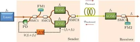
Fig.1.Schematic diagram of passive phase correction setup,with FM denoting Faraday mirror,SMC representing single mode coupler,and PD referring to photon diode.
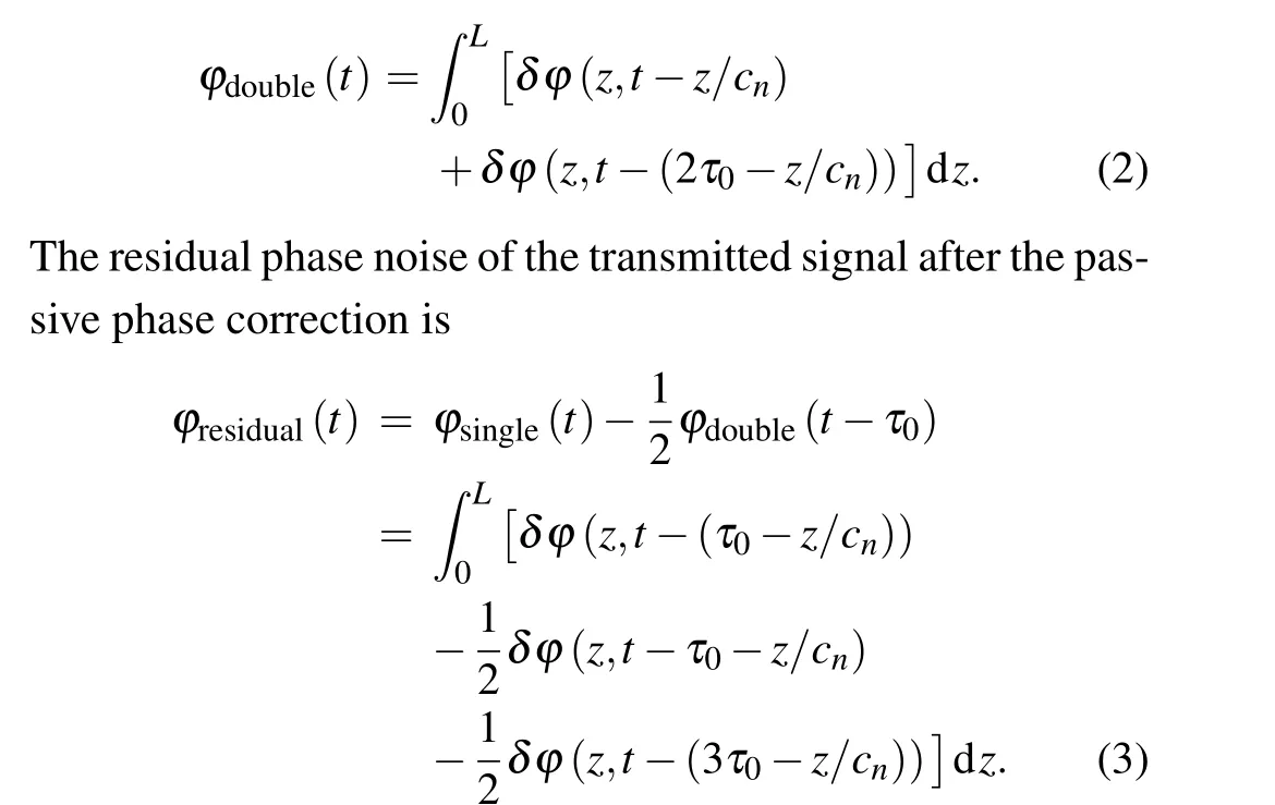
Due to transmission delay,the phase noise of forward signal and backward signal are not totally correlated,which sets a limitation to the noise suppression.[12,19]The phase noise of the fiber is accumulated from the beginning to the end of the fiber,and it is given by
whereδϕ(z,t)represents the phase shift introduced when the signal passes through positionzat the timet,τ0is the time for the signal to travel one-way trip,cnis the speed of light in the fiber,andLis the length of the fiber link.The phase noise for the double-trip signal is displayed as follows:
Using the Fourier transform, the above equations are both transformed into the frequency domain, and equation (3) becomes
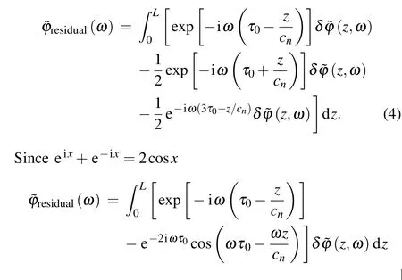
The phase noise spectral density is defined asS(ω) =〈|˜ϕ(ω)|2〉.The total phase noise spectral density integrates all the elements in the fiber since the phase noise of the light inside the fiber is uncorrelated in position.[21]Then,
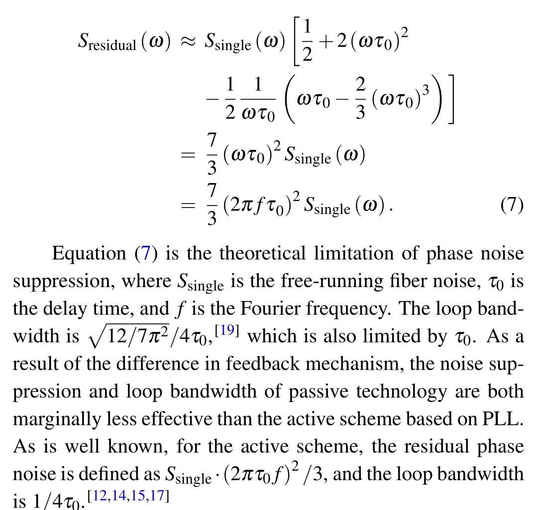
At low frequencies,ωτ0≪1,then equation(6)approximates
To verify the behavior of passive phase noise compensation, 500-km-long optical frequency dissemination via spooled fiber link is investigated.By comparing the transferred signal at the receiver site with the reference signal at the local site,the unstabilized phase noise and the stabilized phase noise are detected simultaneously.Figure 2 shows the phase noise power spectral density(PSD)of the 500-km link.It indicates that the phase noise is effectively canceled within the loop bandwidth by feeding the half of frequency of round-trip beat-note to the AOM at the local site.The feedback bandwidth is about 40 Hz, and the stabilized phase noise exhibits good agreement with the theoretical prediction.For comparison, the theoretical calculation with active method is also shown in Fig.2.At lower frequencies,the active residual noise is lower than that generated from the passive method, but it should be noted that the PSD also has a loop bump at 100 Hz.
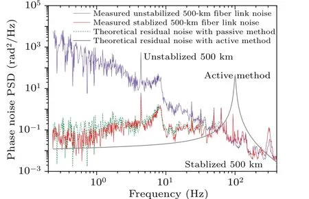
Fig.2.Phase noise of 500-km-long spooled fiber, with violet line denoting unstabilized phase noise, red line representing stabilized phase noise, green dash line referring to theoretical residual noise with passive method,and gray line assigning to theoretical residual noise with active method.
3.The 972-km-long optical frequency transfer link
To examine the performance of long-distance optical frequency distribution by using passive phase noise cancellation,two-cascade coherent optical frequency transmission via 972-km-long fiber is demonstrated.As shown in Fig.3,the transfer link consists of two spans: a 500-km-long spooled fiber link and a 472-km urban fiber link.The entire setup is made up of two similar phase noise compensation devices for the two links and a regenerative amplification devise between the two spans.
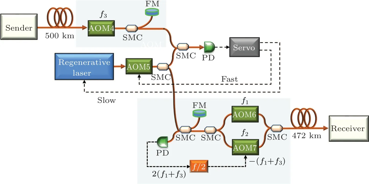
Fig.3.Schematic diagram of 972 km transfer link.
Ten 50-km-long spooled fibers constitute the 500-kmlong link with attenuation of 0.2 dB/km,and five bi-directional erbium-doped fiber amplifiers (Bi-EDFAs) are used to compensate for the optical loss.Bi-EDFA’s gain is restricted to below 18 dB in order to prevent lasting effects,thus,only tens ofµW of the transmitted signal are received at the end of the 500-km-long link.Hence,to achieve enough optical signal power for the second cascaded transmission,a high-gain optical amplification is required.We use optical regeneration to amplify the transmitted signal with a gain of up to 50 dB, by phaselocking a fiber laser(linewidth∼1 kHz)to the upcoming signal from the previous transfer cascade.The optical regeneration is realized by using both slow frequency correction and fast phase locking.[15,22]The slow frequency control is demonstrated by the piezo-electric transducer(PZT)with a response rate of 1 kHz,and the fast phase locking is achieved via AOM with a response rate of tens of kHz.Then the regenerative laser is injected into the second transfer span,which is made up of a 472-km-long urban link.The transmitted signal through the first span is phase-stabilized by a passive phase compensation scheme,so as to realize the second cascade.The power of the signal injected into the second link is about 1 mW, which is equal to the power of the input signal for the first span.
The second link is a 472-km-long urban telecommunication fiber that is comprised of three urban fiber links located in Shaanxi Province, China with average attenuation of 0.28 dB/km.Eight Bi-EDFAs are used in the link to balance the optical loss.For each span, there is an optical monitor for estimating the transfer performance.Through setting the frequency difference between the regeneration laser and the transmitted signal after AOM4 to be 110 MHz and the frequency shift of the repeater station to zero, the effect of different time bases can be eliminated.By dividing a long link into multiple shorter ones,the loop bandwidth and phase noise compensation depend on the length of each span,thus,the entire cascaded transfer link has wider loop bandwidth and larger phase noise cancellation ratio,therefore,it exhibits potential in very-long-distance transmission links.
4.Results and discussion
Phase noise of the link is investigated by measuring the beat-note between the transferred signal at the end of the link and the original signal, which is feasible, for the senders and receivers are located in the same laboratory.The free-running phase noise of the 500-km-long fiber link and 472-km-long fiber link are displayed in the insert of Fig.4.As can be observed, the phase noise of an urban link is much larger than that of a spooled link with the same length, which is mainly due to the different ambient factors.

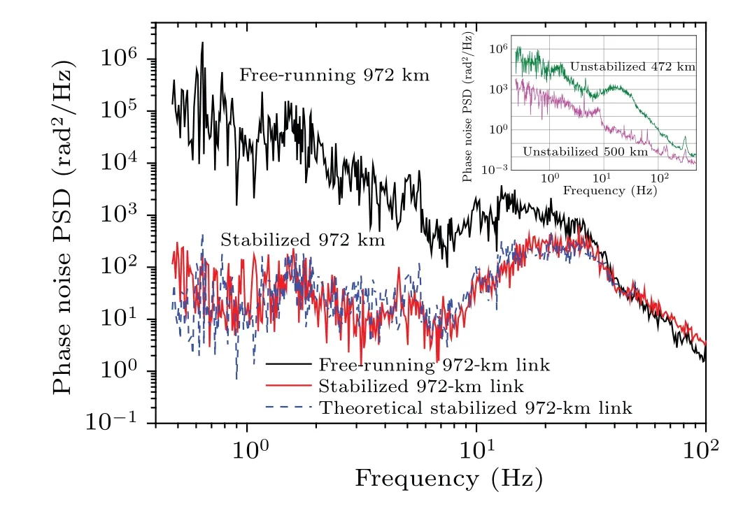
Fig.4.Phase noise PSD of unstabilized 972-km-long link(black line),stabilized 972-km-long cascaded link(red line),and theoretical residual noise of stabilized 972 km(blue line);phase noise PSD of unstabilized 500-km-long link(pink line),and unstabilized 472-km-long link(green line).
To investigate the long-term performance of the 972-kmlong link,the out-loop beat-note between the reference signal and the output signal of the entire cascaded link is measured by using a frequency counter(K+K)working in Λ-type mode with 1-s gate time,because the sender and receiver are located in the same laboratory.Transfer instabilityversustime is evaluated by calculating the modified Allan deviation of the frequency data,and the results are shown in Fig.5.
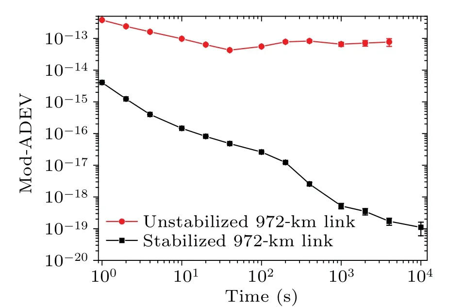
Fig.5.Transmission instability of (500 km+472 km)-long link, with red line denoting modified Allan deviation of the unstabilized 972-km-long link,and black line referring to stabilized 972-km-long link.
The unstabilized 972-km-long link shows an instability of 3.7×10⁻¹³at an averaging time of 1 s.With phase control, the transfer instability of the 972-km-long link reaches 3×10-15at an averaging time of 1 s, 1.7×10⁻¹⁹at 4000 s,and 1.1×10⁻¹⁹at 104s,which verifies the reliability of passive phase noise cancellation in long-distance transfer of optical frequency.The asymmetry between AOM1 and AOM2 of the setup has an influence on the transmission instability,because the phase noise it introduced cannot be compensated for.To reduce the effects of the asymmetry, the length of the connection fiber of the setup is shortened by fusing the fiber,and the optical setup is placed in a sound-insulation box,which reduces the influence of vibration.In addition,for further stabilization of the optical length,the box is temperaturecontrolled to a range of about 10 mK.However,the slow temperature variation in the laboratory still causes a tiny bump at an averaging time of two hundred seconds,and high-precision temperature-control will reduce the influence.
5.Conclusions
In conclusion,we demonstrated a 972-km-long cascaded optical frequency transfer by using passive phase noise cancellation, reaching a transmission instability of 1.1×10⁻¹⁹at 104s.Two AOMs are used at the sender site for the passive phase control technology: one is for phase noise cancellation and the other is for phase noise detection.Without using any PLL electronic circuits,the phase noise is suppressed by feeding the radio beat-note frequency to the AOM at the sender site, preventing a servo bump in the transferred signal while also making the system more compact and robust.The advantage of the passive phase compensation technology is its suitability for long-distance transfer link and noise transfer link without sudden interruptions introduced by over phasecorrections from the servo loop.Future comparisons of optical clocks over very long distances may be able to benefit from these efforts.
Acknowledgements
Project supported by the National Natural Science Foundation of China(Grant Nos.12103059,12033007,12303077,and 12303076),the Fund from the Xi’an Science and Technology Bureau, China (Grant No.E019XK1S04), and the Fund from the Youth Innovation Promotion Association of the Chinese Academy of Sciences(Grant No.1188000XGJ).
猜你喜欢
Chinese Physics B(2023年12期)2023-12-15
初中生学习指导·提升版(2022年4期)2022-05-11
美与时代·美术学刊(2022年3期)2022-04-27
湛江文学(2020年7期)2020-11-19
艺术家(2019年8期)2019-12-16
校园英语·下旬(2018年1期)2018-05-15
河北书画研究(2018年2期)2018-03-07
美与时代·美术学刊(2018年10期)2018-01-25
汉语世界(2017年5期)2017-09-21
校园英语·中旬(2015年12期)2016-01-07
- Chinese Physics B的其它文章
- Unconventional photon blockade in the two-photon Jaynes–Cummings model with two-frequency cavity drivings and atom driving
- Effective dynamics for a spin-1/2 particle constrained to a curved layer with inhomogeneous thickness
- Genuine entanglement under squeezed generalized amplitude damping channels with memory
- Quantum algorithm for minimum dominating set problem with circuit design
- Protected simultaneous quantum remote state preparation scheme by weak and reversal measurements in noisy environments
- Gray code based gradient-free optimization algorithm for parameterized quantum circuit