
Robust free-space optical frequency transfer in time-varying link distances conditions
2024-02-29 09:17ZhouTong童周LeiLiu刘雷JiaLiangWang王家亮QianCao操前ZhiChengJin金志成KangYing应康ShenShengHan韩申生ZhengFuHan韩正甫andYouZhenGui桂有珍
Chinese Physics B 2024年2期
Zhou Tong(童周), Lei Liu(刘雷), Jia-Liang Wang(王家亮), Qian Cao(操前), Zhi-Cheng Jin(金志成),Kang Ying(应康), Shen-Sheng Han(韩申生),3,5, Zheng-Fu Han(韩正甫), and You-Zhen Gui(桂有珍),3,†
1School of Physical Sciences,University of Science and Technology of China,Hefei 230000,China
2Key Laboratory for Quantum Optics,Shanghai Institute of Optics and Fine Mechanics,Chinese Academy of Sciences,Shanghai 201800,China
3Center of Materials Science and Optoelectronics Engineering,University of Chinese Academy of Sciences,Beijing 100049,China
4Key Laboratory of Space Laser Communication and Detection Technology,Shanghai Institute of Optics and Fine Mechanics,Chinese Academy of Sciences,Shanghai 201800,China
5Hangzhou Institute for Advanced Study,University of Chinese Academy of Sciences,Hangzhou 310024,China
Keywords: free-space,optical frequency transfer,variable link distance
1.Introduction
Free-space transmission and comparison of highprecision frequency signals from optical atomic clocks are of great importance in studying the inter-satellite coherent communication systems, satellite navigation, geodesy, very long baseline interferometry, deep space exploration, and gravitational wave detection.[1–5]State-of-art optical atomic clocks can reach fractional frequency stabilities as low as 10-18.[6]While optical fibers can be used to realize remote clock comparison over several hundred kilometers, they are impossible to be applied to the comparison of ground-to-satellite or satellite-to-satellite based optical frequency clocks.This requirement emphasizes the importance of developing new techniques for free-space optical frequency transfer, which can provide higher precision and stability.However, atmospheric turbulence will cause both phase noise and amplitude noise.[7]The former can lead to the phase instability of optical links and the latter will result in reduction of the signal-to-noise ratio.[8–10]
Sprengeret al.first carried out an experiment on atmospheric optical frequency transfer combined with 80-MHz radio frequency(RF)frequency.The relative frequency stability of optical signals achieved was 1.68×10⁻¹³at 1 s.[11]After that, many groups[12–15]also concentrate on free-space optical frequency transfer for higher precision along with longer distance.Notably, in 2022, Gozzardet al.demonstrated a 2.4 km atmospheric optical frequency transfer achieving residual instabilities of 6.1×10⁻²¹at 300 s of integration in fractional frequency.[16]Active optics,namely tip-tilt mirror,was used to suppress amplitude noise and beam wander.For future satellite-to-ground optical clocks’ comparisons, Shen et al.performed a 16-km free-space optical time and frequency transmission and achieved an instability of 4×10-18at 3000 s.[17]The link loss, 72 dB, is comparable to the loss between the ground station and the geostationary orbit(GEO)satellite.Recently,they have also achieved time and frequency propagation as long as 113 km on the free space link, with instability less than 4×10-19at 104s.[18]High power optical frequency combs and large aperture Cassegrain reflectors were used to reduce large link loss.This work has been perceived not only to be used for ground-based applications, but for future satellite time and frequency transmission.
Optical frequency transfer has primarily focused on constant link distance scenarios.However,frequency transfer between moving objects is also of great interest.The National Institute of Standards and Technology(NIST)has studied the clock comparison off an unmanned aerial vehicle (UAV) to address this need.The experiments were based on optical two-way time and frequency transfer technology using frequency comb, and achieved timescale synchronization with a time deviation of less than 1 fs.Frequency stabilities are below 10-15at 1 s and 10-18at 200 s of integration time, for free-space links of 0 km,2 km,and 4 km when the UAV flew at±24 m/s.[19]Reference[20]also gave a solution for optical frequency transfer via a flying drone with a speed of approximately 0.3 m/s, increasing the flexibility of comparisons between free-space optical clocks.The statistical uncertainty of optical frequency is 2.5×10⁻¹⁸after 3 s of integration time.
In this study, we present a simulation of two satellites with a mean anomaly of 160◦separated on the same orbit at an altitude of 5×10⁴km.We calculate the Doppler frequency shifts in one orbital period, and our results demonstrate that the Doppler shifts are highly consistent throughout the entire period,on a scale of approximately 19 MHz with a variation of less than 350 Hz.Given that similar or larger variations may occur in free-space laser links,we suggest that traditional optical frequency transfer technology could potentially compensate for or suppress such variations.It is difficult and complex to allow the remote and local sites of the optical frequency transfer system to move simultaneously, so we employ a single telescope as both transmitter and receiver and use a cornercube reflector(CCR)installed on a sliding guide to reflect the beam.With the active phase noise suppression technology,the fractional frequency stabilities achieved are 1.9×10⁻¹⁶at 1 s and 7.4×10⁻¹⁹at 1000 s while the CCR moves at a maximum velocity of±20 cm/s and an acceleration of 20 cm/s2.That is to say, the equivalent variation of Doppler frequency shift is approximately 0.516 MHz in theory, which is much greater than the frequency fluctuation observed in our simulation results.Our work is to investigate the ability to suppress the optical frequency noise at different motion speeds by using a variable-speed motion platform.This scheme can be used to preliminarily investigate the development of an inter-satellite optical clock network.
2.Simulation and experimental setup
2.1.Simulation and analysis of inter-satellite optical links
The study in Ref.[21]showed that the amount of Doppler shift is approximately±7 GHz for optical links between GEO and low earth orbit (LEO) satellites.After compensation,the residual Doppler frequency fluctuations remain as high as 35 MHz.For traditional optical frequency transfer systems,it is very challenging to compensate for such a large Doppler frequency shift.Therefore, the selection of satellite orbits must ensure that the Doppler frequency shift resulting from the relative motion of two satellites is within the pulling range of typical phase locked loop.
We expect that placing both satellites in the same orbit and increasing the orbital altitude may significantly reduce the Doppler frequency,allowing it to fall within the typical bandwidth of a phase-locked loop (PLL) for compensation.Figure 1 shows the graphics of our model.The distance between the two satellites keeps almost the same, which is∼9.8×10⁴km with variations of only a few centimeters during a whole circle.The right ascension of ascending nodes(RAANs) of both satellites are 102◦.Orbital inclination is zero degrees.Mean anomaly values of the two satellites are specially set to ensure that signals will not be hindered by the earth when it passes through space.
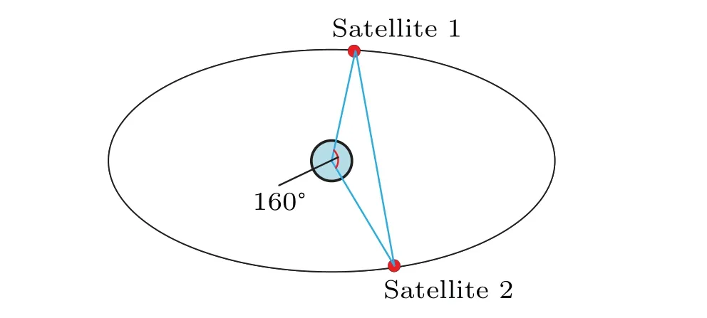
Fig.1.Models of two satellites established.Properties setting are as follows: altitudes of satellites are both 5×10⁴ km; orbital inclination is also the same, equivalent to zero degrees; mean anomaly values for satellite 1 and satellite 2 are 0◦and 160◦,respectively.
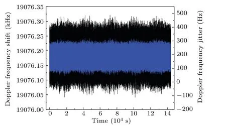
Fig.2.Doppler frequency shift (black lines, outer) and residual frequency jitter(blue lines,inner)calculated due to relative motion of two satellites in one orbital period.
The method to calculate Doppler frequency shifts is detailed in Ref.[22].As shown in Fig.2,the frequency shifts are all near 19 MHz.Although the simulated results are relatively large,we observe that if we subtract 19.076 MHz from all the computed results,then the residual frequency jitter is no more than 350 Hz.The 350-Hz jitter occurs because the relative velocity of the two satellites changes by about a few millimeters per second.Hence the Doppler frequency shift can be written as
wherefDopplerandfδrepresent real Doppler shift and frequency jitter, respectively, andfconstant= 19.076 MHz is a constant.Considering a real system, this constant frequency shift can be compensated for by using an acousto–optic modulator to generate the opposite frequency with the same value,and the residual variations are also able to be suppressed as indicated in the following experimental section,the maximum relative velocity of our terminals reaches close to one meter per second and the compensation for this Doppler frequency also reaches the level of sub-Hertz.
In the design of an inter-satellite optical frequency transmission system, various factors should be considered in addition to the Doppler effect.On one hand, because satellites are in a high-speed motion state, the acquisition tracking positioning (ATP) technology is required.The ATP technology is mainly based on the use of fast steering mirrors(FSMs)and has been extensively studied.[23,24]The FSM serves as a core component of the precision tacking unit in the ATP system.It should have high accuracy,i.e.,a high angular resolution typically in the range of micro-radians or even sub-micro-radians,and high bandwidth(up to hundreds of Hertz or even higher),which is essential to withstand disturbances and jitter caused by the satellite platform, thermal effects, and other environmental factors.
On the other hand, reference [18] realized stable freespace optical frequency transfer under the link loss of up to 89 dB,which is equivalent to the loss of optical signals transfer over a 3.2×10⁵-km-long vacuum on condition that we choose a wavelength of 1550 nm along with a laser beam divergence angle of 22 µrad and a receiving aperture of 250 mm.To demonstrate the feasibility of atmospheric optical frequency transfer in motion,our study focuses on the suppression of the Doppler frequency shift in one-dimensional motion between the transmitting and receiving apertures.This allows us to investigate the potential of atmospheric optical frequency transfer in practical scenarios where the satellite and/or the ground station may be in motion.
2.2.Experimental setup
The experiments were conducted both in laboratory and in corridor.In laboratory, the telescope was set near the end of the sliding guide,while in the corridor,it was placed 70 m away from the guide.Figure 3 shows the location of the corridor.In out-of-laboratory experiments, the telescope, the reflector,and the moving platform are installed in corridor,while other equipment remained in laboratory.
The principle of our compensation system is based on the Doppler noise suppression technique.[25]The schematic diagram of our free-space optical frequency transfer system is shown in Fig.4.The time-varying optical link was formed by transmitting optical signals from the telescope(60FC-T-4-M200-37).The telescope is a small-aperture optical fiber collimator with an integrated tilt adjustment to prevent the aberration caused by vignetting or clipping,and it is reflected from CCR installed on the electric-controlled sliding rail.The maximum moving distance is 80 cm,and it is received by the same telescope.
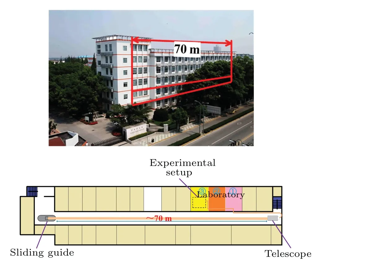
Fig.3.Location of corridor and structure of the second floor.The spatial part of our experiment passed through the corridor of the second floor in building 2 of Shanghai Institute of Optics and Fine Mechanics(SIOM).The laboratory is composed of three rooms.The experimental setup was in the third room and connected with the telescope using a 20-m-long single mode optical fiber.
At the local site, the optical signal was generated by an NKT narrow-linewidth (<0.1 kHz) laser with a 1550.12-nm wavelength and transmitted into the compensation system.The optical signal passed through a 60(up):40(down) optical fiber coupler(OC)and was injected into telescope.The laser beam is transmitted to the CCR through a time-varying freespace optical link,where it was then reflected back to a single telescope.The maximum clean aperture of the telescope was 48 mm and the diameter of parallel beam was 37 mm.The optical power entering the telescope was 1.5 dBm.The optical loss induced by coupling the fiber with the telescope was about 4.5 dB.In the corridor,the optical power jitter caused by turbulence in the telescope is about 1 dBm,while in the laboratory it is within 0.5 dBm.A bidirectional erbium-doped fiber amplifier(EDFA)was placed at the entrance to AOM2 to improve signal-to-noise ratio.Due to the reciprocal atmospheric turbulence, the phase noise of the round-trip is twice higher than that of one-way transmission.At the local site, the optical frequency signal generated from NKT can be expressed as(regardless of its intensity)
whereωis angular frequency.The AOM1, driven by voltage-controlled oscillator under the superior control of a proportional–integral–derivative(PID)controller,namely liquid instruments Moku: Lab,provides a modulation frequency ofω1and phase compensation ofϕc.Then the optical frequency signal emitted from AOM1 is
As the CCR was moving back and forth on the sliding guide,optical signals passed through air space, with its frequency shifting a variable value denoted asfD.To avoid ambiguity,parameterfDis defined as Doppler shift observed from the view of the telescope or the CCR.Afterwards,signals entered into AOM2.Optical signals will fall into endless round trip among the reflector,telescope,and the Faraday mirror,resulting in asymmetrical phase noise between the local site and the remote site.As a single AOM cannot distinguish the forward signal and the backward signal, we use the second AOM to separate them.
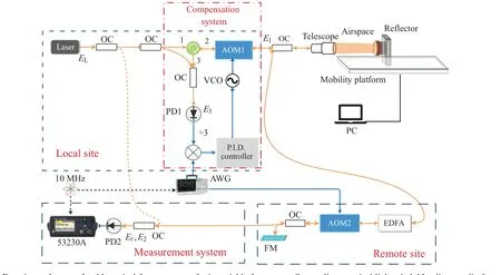
Fig.4.Experimental setup of stable optical frequency transfer in variable free-space.Orange lines: optical links; dark blue lines: radio frequency links.Two AOMs can shift frequency by 80 MHz and-110 MHz,respectively.The sliding guide is 1-m long,and moving range is 80 cm.
At the remote site,one signal beat with the reference signal(orange dashed line)and was detected by a photodetector(PD2).The optical frequency signal arriving at the remote site was as follows:
whereω2is the modulation frequency of AOM2 andϕlis oneway link fluctuation from telescope to CCR.These data were recorded by using a Keysight 53230A frequency counter.The other signal would be reflected off a Faraday mirror (FM),then returned along its original way and the path was AOM2–EDFA–telescope–reflector–telescope–AOM1–PD1.The returning signal also beat with the reference signal.As it is transmitted twice through AOM1 and AOM2,the optical frequency signals into PD1 is
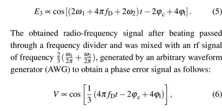
where 1/3 means that the frequency was divided by three in the frequency divider.With compensation system on,ϕc=2ϕl+4π fDt,the output optical frequency signal at the remote site is expressed as the phase independent time-varying link:
3.Results and discussion
In our experiments, free running link refers to the frequency transfer without compensation system but with sliding guide working.Under this condition, the whole system is close to a Doppler velocimeter.Therefore, data shown in frequency counter at the remote site reflects the Doppler frequency shifts due to the relative motion of the telescope to the reflector.
Blue lines in Fig.5 shows both positive and negative Doppler frequency shift as the reflector moves back and forth on the sliding guide.In addition,the real frequency shift when the reflector moves at velocity of 20 cm/s in one direction is nearly 200 kHz, which is two orders of magnitude lager than the simulation result (<1 kHz).Nevertheless, such big Doppler shifts are narrowed within 0.5 Hz(orange line)when the compensation system works.Figure 6 shows the corresponding modified Allan deviation (MDEV) of free-running link(blue)and its compensation link(red).All the data are acquired from 53230A frequency counter(λcounting)[26]under a gate time of 0.1 s and sample time over 4 h, except for the data of system noise floor,which are under a gate time of 1 s and sample time over 12 hours.
The noise floor of the frequency transmission system can reach 2.3×10⁻¹⁸for 1 s and 5.3×10⁻²⁰for 2000 s.In the laboratory,the MDEV of compensated link(red)shown in Fig.6 reaches 1.9×10⁻¹⁶at 1 s and 7.4×10⁻¹⁹at 1000 s with the phase compensation on,for the case of free-running link,it is 3.9×10⁻¹⁰at 1 s and 5×10-15at 1000 s when the phase compensation is off (light blue).It can be observed that with the phase compensation on, the Doppler frequency shift is well suppressed when the reflector moves at a uniform speed, and worse suppressed when the reflector moves during the acceleration or deceleration process.
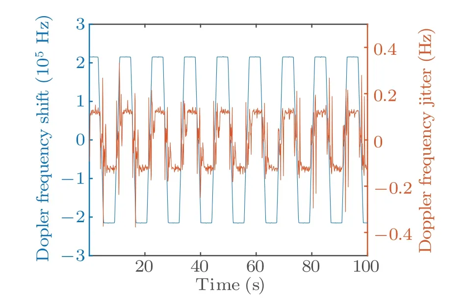
Fig.5.Frequency data of free-running link (blue, outer) and its compensation results(orange,inner)recorded in 53230A.

Fig.6.Variations of modified Allan deviation of optical frequency transfer with averaging time in laboratory.In inset,v denotes maximum speed that sliding guide can reach when CCR moves,symbol“+”represents reflector far away from telescope,while symbol“-”is opposite,and ADT refers to acceleration time or deceleration time.
Due to the relatively low speed of the guide, the waveform of Doppler shift in Fig.5 is trapezium-like.The top of the trapezium illustrates a uniform motion of the sliding guide.Also,the wave form of its compensated link is trapezium-like.If the guide is long enough and the reflector keeps moving away from telescope at a constant velocity, the compensated frequency data will be equivalent to the results of splicing the top part of orange curve in Fig.5.However,the performance of compensated system deteriorates,and even collapses,as we increase the speed of sliding guide,or reduce the acceleration or deceleration time (ADT).The green line in Fig.6 shows the worst performance of the compensation system in laboratory experiment and the MDEV is 5.6×10⁻¹⁶at 1 s and 3.7×10⁻¹⁸at 1000 s under a velocity of 50 cm/s and an acceleration of 33 cm/s2.Meanwhile, the fractional frequency stability is 4.9×10⁻¹⁶at 1 s and 1.2×10⁻¹⁸at 1000 s (violet, diamond) with a higher speed of 70 cm/s and a lower acceleration of 28 cm/s2.Due to the limit of moving range(∼80 cm), for violet curve, the sliding guide does not reach its pre-set maximum speed of∼70 cm/s.The whole round trip just includes the acceleration process and the deceleration process,resulting in a lower maximum speed of 47.3 cm/s and higher frequency stability than the green curve.Meanwhile,a bit higher movement also leads to subtle vibration of the CCR and the sliding guide,we speculate that it is one of the factors affecting the instability of the experiment.
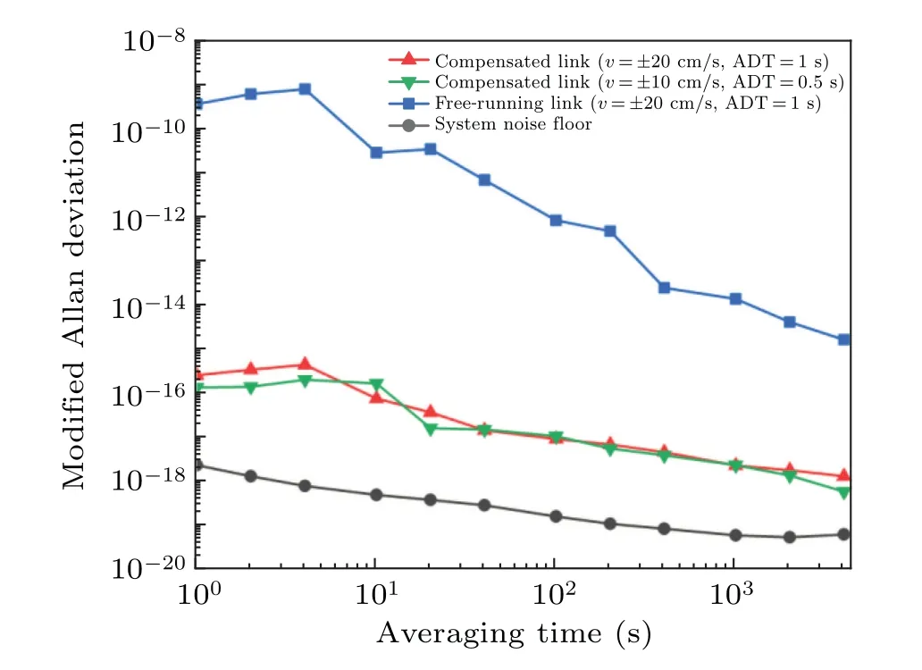
Fig.7.Variations of modified Allan deviation of optical frequency transfer with averaging time in corridor.
We also attempt to connect the free space in the corridor and conduct experiments with the remaining measurement equipment in the laboratory, and results are shown in Fig.7.As the CCR moves at a speed of 20 cm/s, which is the same as the counterpart in compensated link (red curve in Fig.6),and with ADT of 1 s, the frequency stability is 2.5×10⁻¹⁶at 1 s of integration time and 1.3×10⁻¹⁸at 4000 s of integration time (red line in Fig.7).Another experiment (green line in Fig.7)achieves an MDEV of 1.3×10⁻¹⁶at 1 s and 5.8×10⁻¹⁹at 4000 s with a lower moving speed of the CCR.These two results illustrate that the performance of our phase compensation in the corridor experiment is worse than that in the laboratory.In the corridor,although it is not worth mentioning compared with the Doppler effect-induced frequency vibration when the system is under free-running link,the influence of atmospheric turbulence becomes nonnegligible with phase compensation on.Because of the presence of gentle breeze in the corridor,the optical power fluctuations received by the telescope in the corridor are approximately 0.5-dB higher than that in the laboratory.Without active optics,the telescope is unable to correct the wavefront distortions caused by slightly strong turbulence.Therefore,it is necessary to adopt active optical techniques to weaken this limitation in future work.
4.Conclusions
We have demonstrated a method that can realize robust free-space optical frequency transfer in variable link distance conditions.The variable link distance is realized via relative motion of the transmitter to receiver.A PID controlled AOM is used to compensate for the noise caused by atmospheric turbulence and motion of the reflector.The frequency instability obtained at the remote site can reach 1.9×10⁻¹⁶at 1 s and 7.4×10⁻¹⁹at 1000 s under a bandwidth of Doppler shifts of 516 kHz.Another experiment with the same Doppler shifts under the 140-m-long free-space condition achieves frequency instability of 2.5×10⁻¹⁶at 1 s of integration time and 1.3×10⁻¹⁸at 4000 s of integration time.It is worth noting that the experiment in our laboratory achieves a frequency instability of 3.7×10⁻¹⁸at 1000 s even with a reflector speed of 50 cm/s.This speed corresponds to a relative velocity of 1 m/s between the transmitter and the receiver.In addition,the distance between two satellites in simulation part is nearly one hundred thousand kilometers, which corresponds to light attenuation of∼79 dB.Reference[17]simulated the GEO-toground station optical link with a loss of 72 dB and a radial velocity of about 1 m/s for GEO satellite.The frequency instability obtained is 4×10-18at 3000 s.In view of this, we predict that for a satellite-to-satellite optical link with a radial velocity of 1 m/s and a link distance of 105km,the instability of frequency transfer may reach 10-19at 104s.Future work will concentrate on large-scale Doppler shifts compensation.
Acknowledgements
The authors would like to thank Nan Cheng and Zhan Lu for their technical support.
Project supported by the National Key Research and Development Program of China(Grant No.2020YFB0408300),the National Natural Science Foundation of China (Grant No.62175246),the Natural Science Foundation of Shanghai,China (Grant No.22ZR1471100), the Youth Innovation Promotion Association of Chinese Academy of Sciences (Grant No.YIPA2021244),and the Innovation Program for Quantum Science and Technology(Grant No.2021ZD0300701).
猜你喜欢
中国火炬(2023年8期)2023-08-16
Chinese Physics B(2022年11期)2022-11-21
中国生态农业学报(中英文)(2021年8期)2021-07-28
作品(2020年9期)2020-12-09
当代陕西(2019年20期)2019-11-25
中老年保健(2017年7期)2017-05-30
中老年保健(2017年9期)2017-05-30
中老年保健(2017年2期)2017-05-30
中老年保健(2017年3期)2017-05-30
幼儿智力世界(2004年7期)2004-08-29
- Chinese Physics B的其它文章
- Unconventional photon blockade in the two-photon Jaynes–Cummings model with two-frequency cavity drivings and atom driving
- Effective dynamics for a spin-1/2 particle constrained to a curved layer with inhomogeneous thickness
- Genuine entanglement under squeezed generalized amplitude damping channels with memory
- Quantum algorithm for minimum dominating set problem with circuit design
- Protected simultaneous quantum remote state preparation scheme by weak and reversal measurements in noisy environments
- Gray code based gradient-free optimization algorithm for parameterized quantum circuit