
Development of a monochromatic crystal backlight imager for the recent double-cone ignition experiments
2024-02-29 09:18ChenglongZhang张成龙YihangZhang张翌航XiaohuiYuan远晓辉ZheZhang张喆MiaohuaXu徐妙华YuDai戴羽YufengDong董玉峰HaochenGu谷昊琛ZhengdongLiu刘正东XuZhao赵旭YutongLi李玉同YingjunLi李英骏JianqiangZhu朱健强andJieZhang张杰
Chinese Physics B 2024年2期
Chenglong Zhang(张成龙), Yihang Zhang(张翌航), Xiaohui Yuan(远晓辉), Zhe Zhang(张喆),4,5,†,Miaohua Xu(徐妙华), Yu Dai(戴羽),7, Yufeng Dong(董玉峰),7, Haochen Gu(谷昊琛),7, Zhengdong Liu(刘正东),Xu Zhao(赵旭), Yutong Li(李玉同),4,5, Yingjun Li(李英骏), Jianqiang Zhu(朱健强), and Jie Zhang(张杰),
1State Key Laboratory for Geomechanics and Deep Underground Engineering,China University of Mining and Technology,Beijing 100083,China
2Beijing National Laboratory for Condensed Matter Physics,Institute of Physics,Chinese Academy of Sciences,Beijing 100190,China
3Key Laboratory for Laser Plasmas(MoE)and School of Physics and Astronomy,Shanghai Jiao Tong University,Shanghai 200240,China
4Collaborative Innovation Center of IFSA(CICIFSA),Shanghai Jiao Tong University,Shanghai 200240,China
5Songshan Lake Materials Laboratory,Dongguan 523808,China
6School of Science,China University of Mining and Technology(Beijing),Beijing 100089,China
7School of Physical Sciences,University of Chinese Academy of Sciences,Beijing 100049,China
8Department of Astronomy,Beijing Normal University,Beijing 100875,China
9Institute for Frontiers in Astronomy and Astrophysics,Beijing Normal University,Beijing 102206,China
10Key Laboratory of High Power Laser and Physics,Chinese Academy of Sciences,Shanghai 201800,China
Keywords: double-cone ignition(DCI),spatial resolution,x-ray radiography
1.Introduction
The double-cone ignition(DCI)is a new ignition scheme for inertial confinement fusion proposed by Zhanget al.,[1]in which two open–end head-on gold cones filled with segmented target shells are used to confine the imploding by highpower laser beams.Compared to other fusion ignition schemes,[2–5]the DCI scheme can significantly reduce the energy requirements of the driver laser, improve the robustness of the compression and heating processes,and achieve high energy gain with relatively small laser energy.For the DCI target geometry, the gap between the two compression cones is about 100 µm, the radius of the open cone tips is 50 µm, and the plasma stagnation time is about 300 ps.[6,7]Diagnosing the density distribution of the plasma between the cones with high spatial and temporal resolutions is challenging.This facilitates the understanding of the compression,acceleration,and headon collision processes in the double-cone ignition scheme.
Typical approaches to investigate the density of the imploding core include neutron activation,[8,9]neutron recoil-reactions,[10,11]the ratio of secondary yields to primary yields,[12]Compton radiography,[13,14]and x-ray radiography.[15–17]The first three methods primarily rely on neutron production through the fusion process to infer the areal density.Consequently,they are suitable for experiments involving high-yield neutron production.X-ray radiography can be used in experiments without or with less neutron production.It can provide a two-dimensional spatial mapping of the areal density, making it a routine diagnostic in fusion experiments.Among the x-ray radiographic schemes, spherically bent crystal imaging[18–20]stands out due to its unique capabilities,including high flux(large acceptance angle),high spatial resolution,and quasi-monochromatic backlight source.Therefore, it has attracted broad interest in high-energy density physics and inertial confinement fusion experiments.
This paper describes in detail the monochromatic crystal backlight imaging (MCBI) system using CuKαline xray emission designed for the Shenguang-II upgrade facility and its application in the DCI experiments.We investigate the backlighter x-ray intensity under various laser conditions and evaluate the spatial resolution of the imaging system, which established the optimal conditions for the backlighting experiments.We report the application of this MCBI system in the DCI experiments, obtaining the areal density, shape, spatial distribution,and uniformity.
2.Design of the MCBI system
Two typical approaches are usually employed to achieve high temporal resolution with MCBI systems.The first is to use a gated x-ray camera,having a time resolution of less than one hundred picoseconds.[21]The second approach is to utilize an ultrashortKαsource generated by picosecond-duration laser-foil interactions,giving rise to a time resolution of a few to tens of picoseconds.[22]By controlling the delay time between the compression and backlighter-driver lasers,the time evolution of the plasma can be measured with high temporal resolutions.
Figure 1(a) is the schematic of MCBI with ultrashort xray backlighter.The shell material currently employed in the experiments is chlorine-doped plastic(C16H14Cl2)with an initial density of 1.1 g/cm3–1.2 g/cm3.The mass-absorption coefficient of C16H14Cl2is a function of plasma temperature and density.The plasma temperature around the cone tip is below 400 eV at the current Shenguang-II upgrade nanosecond laser capability.Figure 1(b)shows the x-ray transmission as a function of plasma areal density around 10 eV–400 eV for two types of backlighter sources, namely CuKα(8048 eV) and TiKα(4511 eV), respectively.Assuming that the measurable transmission of the x-ray backlight system is in the range of 5%–80%[18](as indicated by the yellow area in Fig.1(b)),the feasible detection range of plasma areal densities accordingly is 7 mg/cm2–118 mg/cm2for CuKαbacklighter and 1.5 mg/cm2–23 mg/cm2for TiKαbacklighter, respectively.When the areal density of the plasma exceeds 23 mg/cm2(for TiKαbacklighter, and 118 mg/cm2in the case of CuKαbacklighter), the transmission of the backlighter would be lower than 5%,which in turn leads to inaccurate measurements.Consequently,the backlight system has been designed to utilize the CuKαbacklight to ensure a more accurate diagnostic of high-density plasma generated around the cone tips.
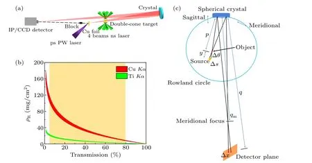
Fig.1.(a)A schematic of the MCBI system in the experiment.(b)Relationship between backlighter transmission and plasma areal density(ρR)around 10 eV–400 eV temperature,where the red area is for Cu Kα (8048 eV)and the green area is for Ti Kα (4511 eV)and the yellow area is for the x-ray transmission of 5%to 80%.(c)A schematic of the optical path of the spherical crystal imaging systems.
For high spatial resolution imaging, a near-normal incidence between 80◦and 90◦is commonly employed in MCBI imaging to minimize the aberration.A quartz (2131) crystal was selected as the Bragg crystal to focus the x-ray with an energy of approximately 8048 eV at a Bragg angle of 88.7◦.The spherically bent quartz crystal,with a radius of curvature of 400 mm,was positioned 225 mm away from the plasma(or grid),while the detector was located 1804 mm away from the crystal,resulting in a magnification factor of 8.02.To enhance the signal-to-noise ratio,a 3 mm thick tungsten block was used to prevent direct incidence of radiations from the picosecond laser onto the detector.The MCBI system was designed to fit the target chamber of the Shenguang-II upgrade facility,[23]located at the Joint Laboratory of High Power Lasers,Shanghai Institute of Optics and Fine Mechanics,Chinese Academy of Sciences.Through the XOP/Shadow simulations,[24]it had been demonstrated that the crystal can image x-rays within the energy range of 8048±5 eV.
3.Investigation of backlighter intensity and spatial resolution of the MCBI system
To optimize the MCBI system, an experiment was conducted to investigate the impact of different laser parameters on the intensity of the backlighter x-ray source and the spatial resolution of the system.The experimental setup has been depicted in Fig.1(a).To generate the x-ray source, an ultraintense picosecond-duration laser beam was employed to irradiate a 20 µm-thick copper foil positioned at 5 mm from the target chamber center(TCC).The four-quadrant gold grid with a bar width of 10 µm and mesh sizes of 60–80–120–160 mesh/cm was positioned at TCC.The x-ray source projected the grid target onto the detector, facilitating the measurement of the spatial resolution of the MCBI system.An Andor iKon-L type charge-coupled device(CCD)and Fujifilm MS type imaging plates(IP)[25,26]were utilized to record the x-ray images.The energy spectrum of the x-ray backlighter was measured using a highly oriented graphite spectrometer(HOPG)[27]with a spectral resolution better than 400, covering an energy range from 7950 eV to 8450 eV.Table 1 displays the parameters of the picosecond laser utilized in the experiment,providing essential details for reference.
Based on the aforementioned laser conditions, the x-ray energy spectra measured with IP detectors are compared in Fig.2(a).The relationship between backlighter intensity and laser energy is presented in Fig.2(b).The red triangles in Fig.2(b)represent the integrated intensity of the images from MCBI,while the black dots indicate the integrated intensity of the backlighter measured by the HOPG spectrometer(Fig.2(a)within the energy range of 8048±5 eV).It shows a positive correlation between the laser energy and the backlighter intensity.

Table 1.Picosecond laser parameters.

Fig.2.(a)X-ray energy spectra measured by HOPG spectrometer under different laser energies.(b)The relative intensity of the x-ray backlighter with different laser energies,where the black dots are from HOPG measurements,and the red triangles are from MCBI measurements.
The backlight images on the IP and CCD detectors are presented in Figs.3(a)–3(d), respectively.Figures 3(a)–3(c)show the results of the grid target imaged on the IP detector under different laser parameters,and Fig.3(d)shows the results imaged on the CCD detector.The knife-edge spread function of the grid is measured at different positions on the images and subsequently differentiated to obtain the line spread function(LSF).The spatial resolution of the imaging system is determined by defining the full width half maximum (FWHM) of the LSF curve and fitting it with a Gaussian function.Figure 4(a)shows the spatial resolutions of the MCBI system for the x-ray sources of different driving laser intensities, where the black dots are for the IP detector and the red dots are for the CCD detector.The figure clearly demonstrates that the CCD has a better spatial resolution of up to 10µm in comparison with the IP detector.This difference is mainly attributed to the resolving capability of the two detectors.The pixel size of the CCD detector is 13.5µm,while for the BAS-MS IP,the actual spatial resolution was measured to be 53 µm[26]when using the Amersham TyphoonTMscanner,even with a 25µm scan parameter.It means that the CCD detector can provide backlight images with higher quality, which is favorable for the MCBI system.Furthermore,Fig.4(a)illustrates a gradual decrease in spatial resolution with laser intensity for the IP detector.This phenomenon can be attributed to the increase in the x-ray source size resulting from the lateral transport of fast electrons at higher laser intensities.[28–30]Other researchers have also found that the size of theKαsource increases with the laser intensity.[31–33]
The spatial resolution of the backlight system depends on the imaging crystal, the x-ray detectors, and the backlight source, etc.Using the XOP/Shadow program,[24]the spatial resolution determined by the imaging crystal is calculated to be 1.0 µm (assuming the crystal is perfectly manufactured),which only plays a subtle role.By taking into account the magnification of the MCBI system, the resolution of the detector is 6.6µm for the case of MS IP and 1.7µm for the case of the CCD camera.
The size of the backlight source also has an influence on the resolution, since different incidence angles will lead

Fig.3.Backlight images of the grid on the IP/CCD detector.(a)Laser energy 19 J,pulse width 1.0 ps,IP detector.(b)Laser energy 96 J,pulse width 3.2 ps,IP detector.(c)Laser energy 444 J,pulse width 10.0 ps,IP detector.(d)Laser energy 281 J,pulse width 10.0 ps,CCD detector.

Fig.4.Spatial resolution of the MCBI system.(a) The spatial resolution with different laser intensities, where the black dots are for the IP detector and the red dots are for the CCD detector.(b)The spatial resolution of the system with different source radii(IPs as detectors),where the black dots are simulation results,and the red triangles are from experimental measurements.
4.Application and experimental results
The developed MCBI system is utilized in the DCI experiments to investigate the spatial distribution and time evolution of the head-on colliding plasma between the cone tips.The nanosecond laser has a wavelength of 0.351µm and an output energy of 1250 J for each beam.Eight beams are focused and overlapped on the shell,driving the shell compression and acceleration,as shown in Fig.1(a).The plasma between the cone tips is imaged by CuKαx-rays generated by the picosecond laser.The evolution of the plasma can be obtained by varying the delay time between the compression laser and the driving laser of the backlighter.
Two-dimensionalKαimages of the collision plasma are presented in Fig.5,where the dashed lines mark the shape of a double-cone target and the dashed circle marks the effective region of x-ray imaging.Note that the bright spots at the top and bottom of each figure are due to bremsstrahlung emission of exploding C16H14Cl2plasma,and the bright spot at the center is the CuKαbacklight image.As shown in Fig.5(b),at 1.2 ns after the end of the compression laser,the C16H14Cl2plasma has been accelerated out of the cone tips with a head-on collision,which formed a clear pattern with reduced intensity at the center due to the absorption of x-rays by the head-on colliding plasma.
Figure 5 compares three x-ray radiographys obtained in similar plasma conditions except probing with differentKαsources driven by different picosecond laser parameters.It shows that an image of the highest contrast and quality was achieved with a large driving energy (493 J), leading to a brightest backlight source, and with a relatively low laser intensity, leading to a relatively small source size, as displayed in Fig.5(b).By analyzing the intensity distribution across the cone wall, we can also conclude that the spatial resolution in the case of Fig.5(b)is superior to that in Figs.5(a)and 5(c),since the backlight intensity across the cone wall increases from 10%to 90%over the shortest distance.This conclusion is consistent with that from Fig.4(a).The spatial distribution of the colliding plasma between the cone tips is clearly demonstrated in this case.With a higher signal-to-noise ratio,it is possible to accurately measure the areal density and provide more precise information about the size and distribution of the plasma.It shows that at the beginning of the head-on colliding process, the plasma still exhibits a symmetrical distribution.The transverse dimension is approximately 150µm(FWHM).
To further explore the dynamic imaging, an analysis is conducted on the background noise level.As can be seen,with an energy of 493 J and a pulse duration of 10 ps for the backlighter laser, the background noise is significantly lower than in other cases.This can be attributed to the fact that the focused laser intensity has a minimum despite its highest energy,resulting in a reduced high-energy x-ray and gamma-ray background.It demonstrates that the highest spatial resolution and the best contrast ratio were achieved with the picosecond laser having a large energy and a relatively long duration.
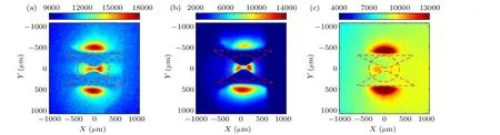
Fig.5.Two-dimensional Kα images of the collision plasma obtained with different Kα sources driven by different picosecond lasers at different delay time.(a)Laser energy of 355 J,pulse width of 2.4 ps,and at 1.1 ns after the end of the compression laser.(b)Laser energy of 493 J,pulse width of 10.0 ps,and at 1.2 ns after the end of the compression laser.(c)Laser energy of 94 J,pulse width of 1.0 ps,and at 1.4 ns after the end of the compression laser.
5.Conclusion
We developed a monochromatic crystal backlight imaging system employing spherically bent crystals for the recent double-cone ignition experiments.The system performance was optimized by comparing the results of varying picosecond laser parameters and the recording detectors.The spatial distribution and time evolution of the colliding plasma between the head-on tips were measured with this system.High quality image was obtained with a higher-energy and longer-duration picosecond laser driver.This system would play an important role in understanding colliding plasma dynamics in the DCI scheme.
Acknowledgments
Project supported by the staff of the Shenguang-II upgrade Laser facility.This study was supported by the Strategic Priority Research Program of the Chinese Academy of Sciences (Grant Nos.XDA25010100, XDA25010300,XDA25030100, XDA25030200, and XDA25051000), the National Natural Science Foundation of China (Grant Nos.11827807 and 12105359), the Open Foundation of Key Laboratory of High Power Laser and Physics of Chinese Academy of Sciences (Grant No.SGKF202105), and the Chinese Academy of Sciences Youth Interdisciplinary Team(Grant No.JCTD-2022-05).
猜你喜欢
戏曲研究(2023年1期)2023-06-27
Chinese Physics B(2022年10期)2022-10-26
Chinese Physics B(2022年5期)2022-05-16
知音·上半月(2020年9期)2020-09-23
婚姻与家庭·性情读本(2019年11期)2019-11-18
青年歌声(2019年2期)2019-02-21
艺术评论(2017年5期)2017-06-14
红蜻蜓·低年级(2015年10期)2016-01-26
电影新作(2014年4期)2014-02-27
红蜻蜓·低年级(2014年2期)2014-02-19
- Chinese Physics B的其它文章
- Unconventional photon blockade in the two-photon Jaynes–Cummings model with two-frequency cavity drivings and atom driving
- Effective dynamics for a spin-1/2 particle constrained to a curved layer with inhomogeneous thickness
- Genuine entanglement under squeezed generalized amplitude damping channels with memory
- Quantum algorithm for minimum dominating set problem with circuit design
- Protected simultaneous quantum remote state preparation scheme by weak and reversal measurements in noisy environments
- Gray code based gradient-free optimization algorithm for parameterized quantum circuit