
Theory and applications of coupled fluid-structure interactions of ships in waves and ocean acoustic environment*
2016-12-26 06:51YoushengWU吴有生MingsongZOU邹明松ChaoTIAN田超CanSIMA司马灿LiboQI祁立波JunDING丁军ZhiweiLI李志伟YeLU陆晔
水动力学研究与进展 B辑 2016年6期
关键词:司马
You-sheng WU (吴有生), Ming-song ZOU (邹明松), Chao TIAN (田超), Can SIMA (司马灿), Li-bo QI (祁立波), Jun DING (丁军), Zhi-wei LI (李志伟), Ye LU (陆晔)
China Ship Scientific Research Center, Wuxi 214082, China, E-mail: wuys@cssrc.com.cn
Theory and applications of coupled fluid-structure interactions of ships in waves and ocean acoustic environment*
You-sheng WU (吴有生), Ming-song ZOU (邹明松), Chao TIAN (田超), Can SIMA (司马灿), Li-bo QI (祁立波), Jun DING (丁军), Zhi-wei LI (李志伟), Ye LU (陆晔)
China Ship Scientific Research Center, Wuxi 214082, China, E-mail: wuys@cssrc.com.cn
Wave induced motions and structural distortions, and machinery or propeller excited vibrations and acoustic radiations of a ship are two kinds of important fluid-structure interaction problems. The branch of ship science that describes the coupled wave induced dynamic behavior of fluid-structure interaction system is referred to as hydroelasticity. During the past three decades the development of three-dimensional hydroelasticity theories and applications gained great progress. Recently the 3-D hydroelasticity theory was further extended to account for the fluid compressibility and the effect of the ocean acoustic environment with finite water depth. A three-dimensional sono-elasticity theory was then produced. In this paper, the 3-D hydroelasticity theory and the 3-D sono-elasticity theory of ships are briefly described. To illustrate the applicability and feasibility of these theories and the corresponding numerical approaches, several examples are presented including the predictions of wave loads, rigid-body and flexiblebody responses, springing and fatigue behaviors, machinery or propeller excited coupled structural vibrations and acoustic radiations, as well as design optimizations for improving safety and acoustic behaviors of ships.
hydroelasticity, sono-elasticity, wave load, structural strength, springing, vibration, acoustic radiation
Introduction
A ship structure continually flexes in a seaway. The loading acting on it actually is neither static nor quasi-static. Hence there continuously exists dynamic interaction between the hull responses and the actions of the surrounding fluid, the so called fluid-structure interaction. To catalog the fluid-structure interaction problems of ships according to the excitation sources, the first kind relate to the fluid action (surface waves, slamming, wet deck impacting, sloshing, vortices disturbance, under-water explosion and acoustic waves etc.) induced steady-state, transient and random motions and structural dynamic responses, as well as the scattered surface wave or acoustic waves, the second kind are the non-fluid action (for example, the onboard machinery and propeller excitations) induced structural vibrations and acoustic radiations. According to different fluid wave properties involved in these two kinds of comprehensive fluid-structure interactionproblems, the fluid surrounding the structure can be treated as the incompressible medium or the compressible medium in the analyses.
When the focus of observation is on the dynamic responses of ships and local structures induced by steady-state or transient-state surface gravity-wave excitations, the change of the fluid density is very small and the influence of the fluid compressibility on the hydrodynamic forces acting on ship structure may be neglected. The reason is that the acoustic wave lengths in the frequency region same as the gravity-wave frequencies are much longer than the characteristic dimensions and the motion-distortion amplitudes of a ship. The theory developed up to now to investigate this kind of fluid-structure interaction problems is referred to as the hydroelasticity theory.
Provided the focus of observation is on the structural responses excited by the under-water explosion shock wave or the incident acoustic wave etc., or on the acoustic radiations produced by structural vibrations, the fluid compressibility must be considered in the analyses. For different situations of intense or weak compressive waves involved in the fluid-structure interaction problems, the theoretical expressions are different. When only the weak compressive wave, i.e.the acoustic wave is concerned the theory describing this kind of fluid-structure interaction problems is called the sono-elasticity theory.
The research of these two kinds of fluid-structure interaction problems closely related to various engineering applications, including the improvement of motion performance and serviceability, insurance of structural safety, control of vibration and noise, enhancement of underwater acoustic stealthy of a ship etc..
In the late 1970s, the 2-D hydroelsticity theory of ships was established as a new branch of ship science[1]. The concept and basic principle to embody the structure and the surrounding fluid as a coupled entirety was further employed and extended in the establishment of the general linear 3-D hydroelasticity theory for an arbitrary shaped flexible marine structure travelling with a forward speed in a seaway in the middle of 1980s[2-4]. Since then, great progress has been achieved in the development and application of 3-D hydroelasticity theories[5]. These include the more rigorous methods of frequency-domain linear analysis accounting for the forward speed effect and the steady flow effect[6], the time-domain linear 3-D theory[5], the non-linear 3-D theory and the numerical methods for a floating structure travelling in rough seas with large motions[7-9], experimental techniques of 3-D flexible ship models[5,10], the hydroelasticity-based design and safety assessment[5]etc.. When a floating structure is placed near islands and reefs, the complicated geographic environment including the varied seabed topography and the inhomogeneous wave statistics may greatly influence its hydroelastic responses. This was also investigated[11,12].
During the last decade, the 3-D hydroelasticity theory[2-4]was extended to include the effect of fluid compressibility by replacing the Green’s function for incompressible fluid with that for uniformly distributed ideal compressible fluid in semi-infinite domain[13]. This enables the acoustic responses and radiations of ship structures to be predicted with the free surface and the forward speed effects being included[14]. Later on it was further incorporated with the Green’s function of the Pekeris ocean hydro-acoustic waveguide model[15]to produce an approach for prediction of ship acoustics in shallow sea. The seabed condition is then represented by a penetrable boundary of prescribed density and sound speed. A 3-D sono-elasticity theory of ships in shallow sea hydro-acoustic environment was then created together with the corresponding numerical methods[16,17]. This has provided an efficient new approach to predict both the machinery excited structural vibrations and the radiated noise in the near or far field surrounding the ship in shallow or deep sea.
Based on the 3-D hydroelasticity theory, the software 3-D Hydroelastic Analysis of Floating and Translating Structures[18](THAFTS) and the acoustic module THAFTS-Acoustic[19]with a user friendly interface for pre-processing and post-processing were developed by China Ship Science Research Center. Since 1980s, THAFTS has been validated by model tests and full scale measurements and improved based on feedback from engineering applications.
In this paper, the 3-D hydroelasticity theory and the 3-D sono-elasticity theory of ships are briefly described. Several examples are presented to illustrate the applicatins of the theories and numerical approaches in the predictions of wave loads, rigid-body and flexible-body responses, springing and fatigue behaviors, machinery excited structural vibrations and acoustic radiations, propeller-shaft-hull coupled vibrations and acoustic radiations and also in design optimizations for improving safety and acoustic behaviors of ships and other marine structures.
1. Brief description of the 3D hydroelasticity and sono-elasticity theories of ships
1.1 The 3-D Hydroelasticity theories of ships and other floating structures
1.1.1 The linear theory[2-4]
The hydroelastic and sono-elastic behaviors of a ship are observed in an equilibrium coordinate system Oxyz , with x -axis pointing from stern to bow,x-y plane on the undisturbed water surface,z-axis pointing upwards and passing through the equilibrium position of the gravity center of the ship. By introducing the principal coordinates, the displacementof the structure is expressed as the aggregation of the principal modesof the structure in vacuum:

The generalized equations of motion may be represented in terms of qrin the matrix form
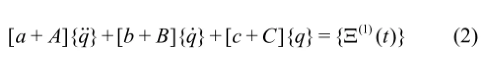
where [a],[b]and[c]are matrices of generalized modal intertial, modal damping and modal stiffness of the dry structure.{q}andare the principal coordinate vector and the first-order (linear) generalized wave exciting force vector respectively.[A],[B] and [C]are the matrices of generalized hydrodynamic inertia, damping and restoring coefficients respectively.and[B]are defined by the integrals ofincident, diffraction and radiation wave potentialsandover the mean wetted surface S. For a ship traveling in a regular sinusoidal wave with encounter frequencyωe, the components of hydrodynamic coefficients[A],[B], [C]and the wave exciting forcesmay be expressed in the form

It is essential that the radiation flow must satisfy the fluid-structure interface boundary condition over the wetted surface. It was proved that the interface boundarycondition on the wetted surface of a flexible body is ofthe following form[2-4].
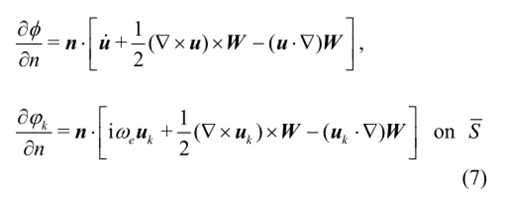
The boundary condition for the diffraction potential is
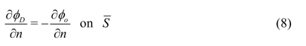
Equation (7) for solving the source strength σkand Eq.(2) for solving the principal coordinates qr( t)provide the coupled equations of the linear hydroelasticity theory.
1.1.2 The non-linear theory[7-9]
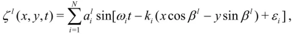
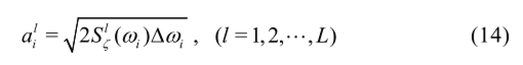
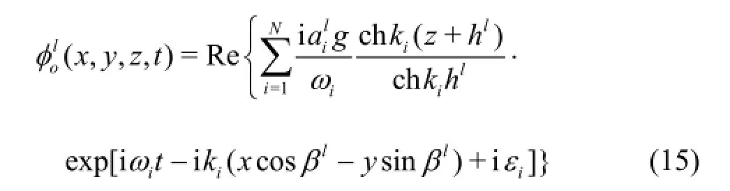
To account for the non-linear hydrodynamic excitations in the fluid-structural interactions of a ship in rough seas, a 3-D non-linear hydroelasticity theory was proposed, where the contributions of the first-order (linear) wave potentials and responses to the second order hydrodynamic actions on a flexible body were included. This theory is especially for prediction of nonlinear hydroelastic responses of a ship traveling with a constant forward speedU in irregular wave of the amplitude ς(t)and energy spectrum Sς(ω):
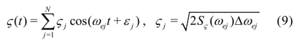
The first-order linear wave potential and wave exciting force in irregular waves have the forms
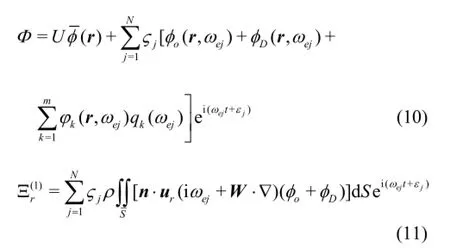
To take into account the nonlinear hydrodynamic actions, two nonlinear generalized force termsandare added on the right side of Eq.(2) to achieve
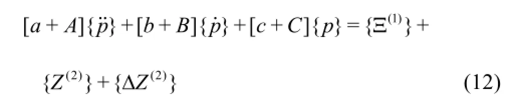
where{p}is the total non-linear principal coordinate. {Z(2)}comes from the effect of the rigid body rotations on the variations of the normal vectors of the body’s wettedsurface between its steady-state position and thedisturbed position to the secondorder[7],is resultant from the hydrodynamic pressure acting on the varied area of the instantaneous wetted surface with regard to the mean wetted surface∆S= S( t)-S. It was verified that this force may be represented by a line integral along the water lineCwof the body at its mean position[7].
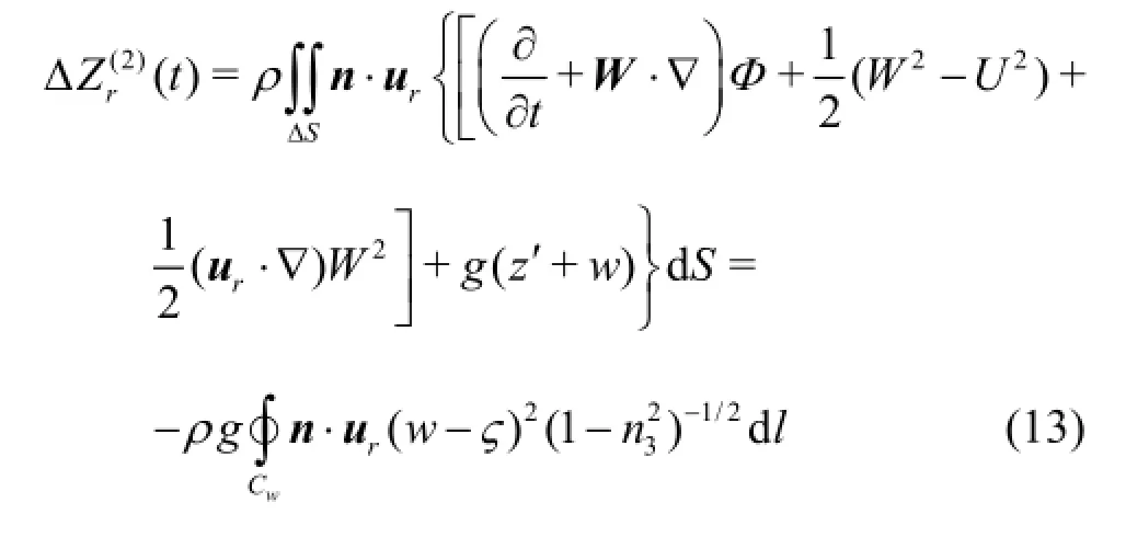
wherez′is the vertical coordinate of the body-fixed axes system.(w- ς)is the relative vertical displacement of the structure with regard to the local wave elevationς.n3is the vertical component of the normal vector of the body’s wetted surface. These nonlinear exciting forces produce the wave frequency components, difference- frequency and sum-frequency components, of which the expressions may be found in Refs.[7] and [8]. Thus the total non-linear principal coordinate{p}may also be decomposed to wave frequency components, difference-frequency and sumfrequency components. The corresponding numerical scheme was developed and the code was produced as a partof THAFTS[19].
1.1.3 The analysis method of VLFS in complicated geographic environment
When a small- or medium-size floating structure is deployed near islands and reefs in shallow water, the encountered wave conditions and the structural responses may be greatly influenced by the varied seabed topography. On the other hand, when a very large floating structure (VLFS) of the length up to several kilometers is placed in a lagoon, although its dimension makes it unlikely to be close to islands and the seabed underneath may approximately be even, the wave statistics along its length may usually vary with locations due to wave scattering from the islands and reefs. In such a complicated geographic environment, the characteristics of wave evolution have to be clarified, and the corresponding hydroelastic analysis approaches have to be developed[11].
To this regard, the wave propagating area is divided into three zones[12]as shown in Fig.1. In the Mega-scale Zone the waves grow and propagate for several hundred kilometers. The wave calculation software such as SWAN and WW3 (Wave Watch III) may be used. In the Middle-scale Zone, the Boussinesq equation[21], mild-slope equation[22]and Green-Naghdi equation[23]can be employed to simulate the wave refraction, diffraction, and dispersion near shore or islands, as well as to provide the incident wave elevation at the site of the floating structure. To convert the Middle-scale Zone wave elevation to the incident wave velocity and pressure over the wetted surface of the structure, and to solve the diffraction potential φD, the radiation potential ϕk(k =1,2,… ,m)and the hydroelastic responses, a Local-scale Zone surrounding the structure is introduced[12]to account for the uneven seabed effect and the inhomogeneous incident wave effect.

Fig.1 Sketch of the mega-, middle- and local-scale zones
In the Local-scale Zone two approaches of hydroelastic analysis of a medium size floating structure or a VLFS may be used:
(1) The simple approach

(2) The Rankin source approach
The second approach is to introduce an imaginary vertical closed boundary from the free surface to the seabed surrounding the Local-scale Zone with the floating body inside. In this local-scale inner region the Rankin sources are distributed over the whole boundaries including the wetted surface of the floating structure, free surface and seabed. On the imaginary boundary the continuity relation is used to link the Middle-scale Zone solutions of wave elevation and vertical distribution of fluid velocity with the potential solutions of the inner-region fluid motions.
1.2 The 3-D sono-elasticity theory of ships in pekeris acoustic waveguide environment[16,17]
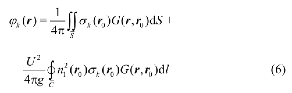
Equations (1)-(4) and Eqs.(6)-(8) are still valid in description of the coupled interaction between the structural vibrations and the acoustic radiations of a ship in an acoustic fluid field, except that the velocity potential φnow satisfies the Helmholtz equation in frequency domain[24]
where k=ω/c is the wave number,ωandcare the acoustic wave frequency and the wave speed respectively. The corresponding Green functionG( r, r0)is a solution of the inhomogeneous Helmholtz equation for waves of harmonictime dependence, andsatisfies the free surface and thesea bed boundary conditions[24]

where δ(r-r0)is the 3-D Dirac delta function. This Green function represents the hydro-acoustic field produced by a point source at r0.
The forward speed of a ship is much smaller than the sound speed cin water. Hence in acoustic analysis the influence of forward speed on the free surface boundary condition may be neglected, the Green function of zero forward speed is acceptable in Eq.(6), hence the Pekeris waveguide Green function[24]may be employed to describe the shallow sea acoustic environments in the 3-D sono-elastic analyses. The Pekeris waveguide assumes that the free surface is a plane pressure-release boundary of the sea water, the seabed is a plane penetrable boundary represented by a half space medium with known density and sound speed.
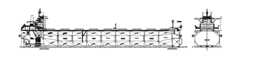
Fig.2 A 180 000 DWT bulk carrier
The mechanical excitations acting on ship structure are usually described by concentrative forces Fj(xj,yj,zj)(j =1,2,… ,N). The mechanical excitations need to be added to the generalized wave exciting force vector previously expressed by Eq.(5), leading to
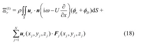
Based on the software THAFTS, the acoustic module THAFTS-Acoustic was developed. It may be used to a floating structure traveling on or under water surface, to solve the source strengths by employing Eqs.(6), (7) and the Pekeris waveguide Green function, obtain the solutions of the principal coordinates from Eqs.(2)-(4) and (18) for prescribed machinery excitations, calculate the structural vibrations and the acoustic radiation potentials based on Eqs.(1) and (6), and finally predict the radiated sound field in water surrounding the ship, which are represented by the acoustic pressure and the sound power respectively as follows:
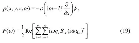

Fig.3 Time histories of the linear and non-linear midship vertical bending moment of the bulker in head irregular waves of sea state H1/3=4.0 mand T01=7.1s, with the design speed of 15 kn
where the superscript∗denotes complex conjugate. The acoustic radiation pressure level is defined as
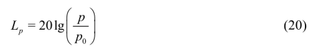
p0=1µ Pa, is the reference pressure.
2. Application examples
2.1 Linear and nonlinear hydroelastic analyses of marin structures
2.1.1 Wave loads of a large bulk carrier[25]
The linear and non-linear methods were employed to predict the motions, wave loads, springing responses and the forward speed effect of a 180 000 DWT bulk carrier (length 285.0 m, breadth 46.0 m, depth 24.8 m and draught 18.0 m, Fig.2) in full load condition traveling in regular and irregular head waves with the forward speed 15 kn.
The predicted time histories of the linear and nonlinear midship vertical bending moment (VBM) of the bulker in head irregular waves of the sea state H1/3= 4.0 m and T01=7.1s, with the design speed of 15 kn are illustrated in Fig.3. It shows that when the magnitudes of the midship VBM are examined, the waveand rigid-body-motion induced component (Fig.3(a)) is lower than the combined linear prediction including the springing component (Fig.3(c)) for about 14%, and lower than the combined nonlinear prediction (Fig.3(e)) for about 30%, the second-order component (Fig.3(d)) contributes about 28% in magnitude of the total springing bending moment.
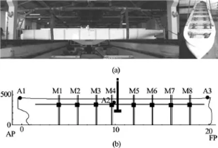
Fig.4 The segmented model of the 500 000 DWT ultra large ore carrier
2.1.2 Springing and fatigue behaviors of an ultra large ore carrier in waves[26]
When an ultra large ship as the 500 000 DWT ore carrier (length 410 m, breadth 68 m and draught 23.3 m) is traveling in irregular waves with relativelysmall characteristic wave period, the two-node bending response appears frequently. It is then difficult to distinguish, based on the traditional concept, the waveinduced and springing-induced loads. The hydroelastic analysis may clearly describe the contributions of different response components, yet it is not easy to do so in model or full scale tests. Both the hydroelastic analysis and the model tests of this ship were performed[26]. Figure 4 shows the segmented model with the scale of 1:73.5, and the positions of the strain gauges M1-M8 along two longitudinal back bones and the acceleration transducers A1-A3.
Figure 5 exhibits the comparison of the predicted and measured response amplitude operators (RAOs) of the pitch motion and the VBM at the midship section. Evidently good agreement is achieved. In the sea states with shorter characteristic wave periods (6.45 s and 7.69 s for example) the linear and non-linear predictions of the significant values of midship VBMs are only about 1.8%-13.6% higher than the model test results.

Fig.5 RAOs of the rigid body motions and the vertical bending moment (β =180o)
The resonant frequency of the 2-node vertical banding mode of such a large ship in water is around 0.3 Hz, or 2 rad/s. This is just in the wave frequency range of usual sea states, and induces the springing responses. For example when the characteristic wave period is 8.5 s, the springing induced significant value of the midship VBM can be about 20.8% higher than that only induced by wave and rigid body motions at any significant wave height.
The hydroelastic analysis provides a direct fatigue assessment approach. The procedures of short and long term fatigue damage assessment of the ship structure was described in Ref.[26]. When this ultra large ship is traveling in full load condition in three possible shipping course lines as shown in Fig.6, the long term fatigue damage assessment shows that the springing induced fatigue damage of the deck stiffener A and that of a bottom stiffener B (Fig.7) could reach about 52% to 78% of the total fatigue damage in its life cycle[26].
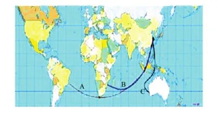
Fig.6 The three shipping lines (A: China-Brazil, B: China-Africa, C: China-Australia)

Fig.7 The midship cross sections of the ship showing the stiffeners where the fatigue damage was examined
2.1.3 Hydroelastic analysis of floating bodies in complicated geographic environment
To illustrate the influence of complicated seabed bathymetry on the hydroelastic responses of a small or medium-size floating body deployed near an island, and the influence of inhomogeneous distribution of wave statistics on the hydroelastic responses of a VLFS in the center part of a lagoon with relatively even seabed, a single semisubmersible-type module and a VLFS consisting of three longitudinally connected modules were taken as examples to be investigated numerically and experimentally[12]. Each module is of the length 300m, breadth 100 m, depth 27 m and draft 12 m with five pontoons and ten columns.
(1) The effect of inhomogeneous incident waves
The three-module VLFS is shown in Fig.8. There are two connectors at each conjunction. The uneven sea bottom topography is shown in Fig.9.
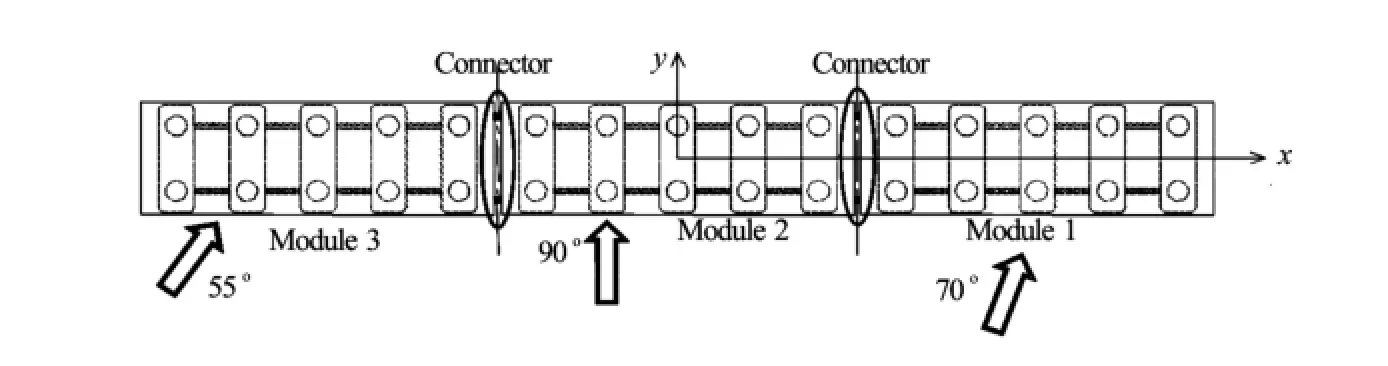
Fig.8 The three-module VLFS and the schematic of inhomogeneous directional regular waves

Fig.9 Bathymetrical contour of the uneven seabed of middlescale zone

Fig.10 The field wave measurement

Table 1 Wave characteristics observed by the field measurement
A wave radar station on an island shown in Fig.10(a) was used to measure the wave characteristics at three quadrilateral regions (Fig.10(b)) where the three-module VLFS is imaginarily deployed with water depth 40 m in a lagoon and about 2 700 m away from the island. The recorded averaged wave characteristics in the three regions are listed in Table 1. It clearly shows that even in the three tiny regions the wave statistics are inhomogeneous.
At first, “the simple approach” with even seabed was employed to predict the responses of the VLFS in one inhomogeneous regular wave condition (regular waves of same amplitudes but different directionso70, 90oand 55ofor the three modules as shown in Fig.8) and three homogeneous regular wave conditions (regular waves in three directions of 70o,90oand 55oindividually for whole modules). The predicted connector forces are shown in Fig.11. It illustrates that the waves of inhomogeneous directions produced much higher results.
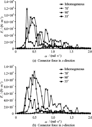
Fig.11 Predicted connector forces in regular waves of homogeneous and inhomogeneous directions
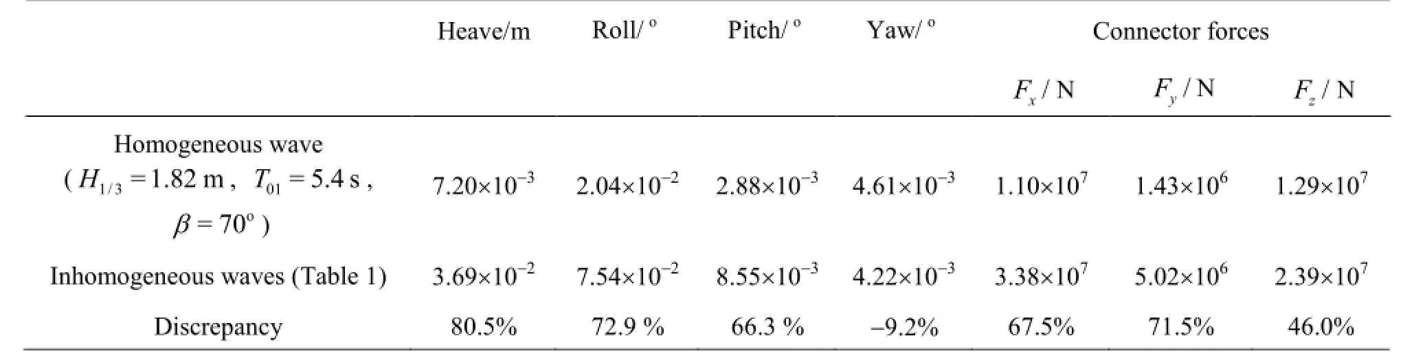
Table 2 Significant values of the VLFS responses in inhomogeneous and homogeneous direction waves
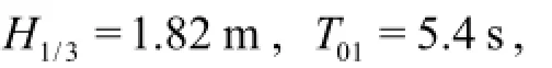
Figure 12 shows the comparisons of the predictions and the test results of RAOs of roll motions and vertical bending moments of a single module in the sea of uneven and even seabed. The incident wave angle is 45o. It shows that the uneven seabed effect is evident in the low frequency region, and makes the responses decreased, particularly at the resonant frequency regime. The results with uneven seabed agree with the test results quite well.
2.2 Sono-elastic analyses of ships
2.2.1 Radiation noise assessment of a large LNG ship[16]
It was reported that the noise of frequencies lower than 100 Hz is particularly harmful to marine fishes by altering their life habits, reproduction and survival abilities. A large portion of noise energy radiated by propeller or machinery excited ship structure is in the frequency range below 100 Hz. The structural radiation noise of a membrane-type LNG ship of storage 147 km3(Fig.13(a)) excited by the propeller-produced pressure fluctuations is predicted. The seabed condition is described by the density 3 000 kg/m3and sound speed 2 050 m/s.
Due to the interference of multi-reflection waves between the water surface and the seabed, the curves of added-mass coefficients fluctuate with regard to frequencies as shown in Fig.13(b). The difference frequencies between two adjacent hills of each curve are the same. Its half wave length exactly equals to the corresponding water depth.
When the excitation is a unit pulsating force of frequency 22 Hz acting vertically at the stern wet-deck, the distribution of the sound pressure radiated by the ship in the sea of water depth 120 m is exhibited in Fig.13(c). The model test results of the propeller-pro-
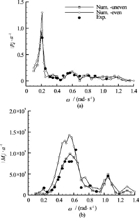
Fig.12 RAOs of roll motions and vertical bending moments of a single module
(2) The effect of uneven seabed
The model tests of a single module in the scale 1:100 were carried out in Ocean Engineering Basin of Dalian University of Technology to investigate theduced pulsating forces are used to predict the propeller-excited radiation noise of the ship traveling at 19.5 kn. The predicted 1/3 octave radiation sound source levels of the 4 bandwidths are shown in Table 3. The total radiation sound source level reaches as high as 182 dB.
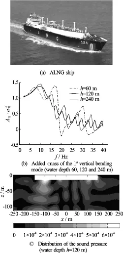
Fig.13 A LNG ship (length 292.00 m, breadth 43.35 m, depth 26.25 m, draught 11.00 m) and its acoustic behavior
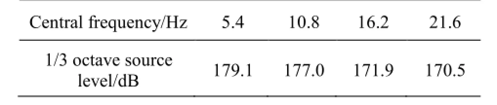
Table 3 The predicted radiation source level of the ship at 19.5 kn excited by the propeller

Fig.14 A 1 500 t ocean-survey SWATH ship
2.2.2 Vibration and noise analysis and optimal design of a SWATH Ship
The coupled fluid-structure vibrations and acoustic radiations of a 1 500 t SWATH ship (length 65.8 m, beam 23 m, draught 5 m, distance between the centerlines of the struts 18 m) as shown in Fig.14 were analyzed using the software THAFTS-Acoustic[19], and also measured in the open sea of water depth 30 m and 65 m with the seabed reflection coefficient 0.429 respectively.
(1) Analysis of vibration and radiation noise
To calculate the RAOs of vibrations and underwater sound radiations of the twin hulls excited by two driving motors in the rear cabins of two lower hulls, a vertical harmonic force of unit amplitude and frequency 25 Hz is applied on the foundation of each motor. 25 Hz is its peak excitation frequency when the ship is traveling at 12 kn. Fig.15 and Fig.16 illustrate the distribution of the predicted vibration acceleration level over the ship hull and the distribution of the predicted sound pressure levels over a cylindrical surface at a radial distance 15 m from the longitudinal axis of the equilibrium coordinate system respectively.
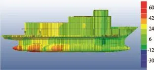
Fig.15 The contour of vibration acceleration level of ship hull at frequency 25 Hz (Reference acceleration 1 µm/s2)

Fig.16 The contour of sound pressure level at the radial distance 15 m at frequency 25 Hz
(2) Comparison of predictions and sea trial results[27]
When the SWATH ship was traveling at 6kn, the major machinery excitations were the two driving electric motors, two main electric generators and two subsidiary electric generators on the deck of the upper box. If a harmonic exciting force of unit amplitude is applied at the base of a machine, the sono-elastic analysismay provide the velocity at the excitation position and the far field acoustic pressure. The former actually provides the effective mechanical impedance at this position, and the later is the RAO between the exciting force of the machine and the acoustic radiation pressure. The actual exciting force spectrum of each machine may be obtained from the measured acceleration spectrum at its foundation, and the predicted effective mechanical impedance. Multiplication of the exciting force spectrum with the corresponding RAO of the acoustic radiation pressure provides the component of radiation noise contributed by this machine. The resultant acoustic pressure is the superposition of all components.
In the sea trial at 6kn the radiation noise was measured by a hydrophone located 7.5 m beneath the water surface at a distance 65 m from the longitudinal central plane of the ship to starboard. Figure 17 illustrates the comparison of the predicted and measured“radiation sound source levels” expressed by the decibel (dB) with the reference pressure 1 µPa. These were obtained from the predicted and measured results at a field point (x, y, z) =(0 m,65 m,-7.5 m). The comparison exhibits similar tendency and fairly good agreement in magnitudes. One cause of the discrepancies at the frequency region lower than 40 Hz is that the foundation accelerations were measured when the ship was stationary by the wharf, while the radiation noise was measured in an open-sea trial.
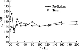
Fig.17 Comparison of radiation sound source levels obtained from the predicted and measured results at (0, 65 m, -7.5 m)
(3) Optimization of the low-noise strut structure
When the SWATH ship was moored in waves and laying down the instruments for ocean survey, it was observed that the waves moving between the two struts continuously hit and excited the vertical side walls of the struts, resulting in vibrations and acoustic radiations in the frequency band below 100 Hz. This is the phenomenon of local-structure hydroelastic response that disturbs the ocean survey performance. To depress this disturbance, the software THAFTS-Acoustic was used to investigate the vibration and sound radiation behaviours of a typical stiffened plate of the struts as shown in Fig.18 (referred to Design-1) and the whole SWATH structure to find the optimized design of the local structure. In this analysis, the water depth is 65 m.
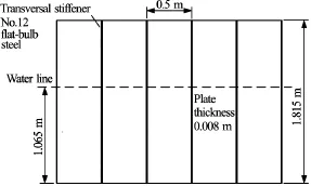
Fig.18 A piece of the side wall stiffened plate of the strut (Design-1)
To examine the dynamic behavior of the plate acted by wave actins, a uniformly distributed harmonic exciting pressure was imposed over the wetted surface below the water line. The acoustic radiation pressure levels for different designs of the stiffened plate were calculated. The predictions revealed that the most important mode with the wet resonant frequency 60.1 Hz gave the largest contribution to the first peak on the curve of the acoustic radiation source level. Based on the predictions it was proposed to add three longitudinal stiffeners with 10% of weight increase, referred to as “Design-5”. Figure 19 shows the radiation sound source levels corresponding to the Design-1, Design-5 and Design-6. where Design-6 is the one that laid the damping layer on the wetted surface of Design-5 and increased the structural damping factor from 0.016 to 0.16. Evidently, compared with Design-1, the radiation sound source levels of Design-5 and Design-6 are reduced bout 5.8 dB and 7.5 dB respectively.

Fig.19 The radiation sound source levels for three structure designs
When the acoustic radiation of the whole ship is investigated, the corresponding local wave excitingforces may be represented by Finand Foutas shown in Fig.20(a). Along the longitudinal direction the exciting forces are distributed on 5 regions. It is assumed that the magnitude of the wave exciting pressure is 0.022 N/m2, and the resultant wave exciting force on the 5 regions is 1 N. The phase angles of the exciting forces among different regions are uncorrelated random.
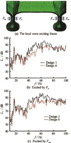
Fig.20 The local wave excitations and the radiation sound source levels corresponding to two designs of the strut plate
Responding to the local wave excitations as expressed by Fig.20(a), the acoustic radiations of the ship with the original and the optimized strut structures (Design-1 and Design-6) are illustrated in Figs.20(b) and 20(c) respectively. The acoustic radiation source level of the optimized design is apparently lower than the original design. The averaged reduction is about 3.8 dB in the frequency range from 10 Hz to 100 Hz.
2.2.3 Propeller-shaft-hull coupled vibration and acoustic radiation[28,29]
The propeller induced exciting force usually transmits along the shaft, acts on the thrust bearing base (TBB), and generates the propeller-shaft-hull coupled vibrations and acoustic radiations of a submerged floating vehicle. The mechanism and control technique of this kind of radiation noise is one of the most complicated problems in the field of theoretical and applied dynamics and acoustics of submerged vehicles.
To investigate how the location and the supporting structure of the TBB influence the acoustic radiation level, the vibrations and acoustic radiations of a small steel model of radius 1.2 m and total length 11.5 m, mounted with propeller-shaft system as shown in Fig.21(a) was calculated[29]by employing THAFTSAcoustic. The plate thickness of the cylindrical hull is 6 mm, and the plate thickness of other part of the hull is 4 mm. The Finite element model of the dry hull and the mesh of the wetted surface of the model are shown in Figs.21(b), 21(c).
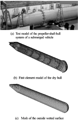
Fig.21 The experimental and numerical models of a submerged vehicle
Case 5 in Fig.22(a) illustrates the traditional TBB on the foundation welded downward to the cylindrical hull and is referred to as the “asymmetric TBB”. Case 6 and Case 7 in Figs.22(b), 22(c) are the two alternative installations of the TBB. The first is supported on an axially symmetric foundation surrounding the water tight bearing at the pole of the hemispheric hull. The second is supported on a symmetric frame that is connected in the radial direction to the intersection of the cylindrical hull and the tail hemispheric hull. These are called the “symmetric TBB”.
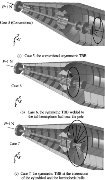
Fig.22 Different locations and the supporting structures of the thrust bearing base
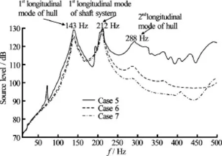
Fig.23 RAOs of the radiation sound source levels of the propeller-shaft-hull coupled system with different installations of the TBB
When the propeller induced axial exciting force Fis assumed sinusoidal with magnitude 1 N, the predicted radiation sound source levels of the hull (RAOs) for these three cases are exhibited in Fig.23. The peak values appear at the frequencies of 143 Hz, 288 Hz and 212 Hz. These are the resonant frequencies of the 1stand 2ndlongitudinal vibration modes of the hull, and the 1stlongitudinal vibration mode of the shaft system respectively. Evidently, in the three cases the major contributions to the radiation noise are attributed to the responses of the 1stlongitudinal vibration modes of the hull and the 1stlongitudinal vibration mode of the shaft system. Due to asymmetric installation, more lateral bending modes of the hull are excited in Case 5, resulting in the higher radiation sound source levels than the cases of the symmetric TBB. The total radiation sound source levels in two frequency ranges 10 Hz-500 Hz and 250 Hz-500 Hz for the three cases are listed in Table 4. It indicates that a symmetric thrust bearing base supported on the intersection of the cylindrical hull and the tail hemispheric hull would produce the lowest propeller-shaft-hull coupled acoustic radiation.

Table 4 RAOs of the total source levels of the propellershaft-hull coupled acoustic radiation (dB)
3. Conclusions
Great progress has been made in the field of hydroelasticity and sono-elasticity theories and the corresponding numerical approaches to better meet the increasing requirements of analyzing the global and local wave induced structural responses, as well as the machinery or propeller excited vibrations and acoustic radiations of ships. Some theoretical creations and application results of the progress are roughly summarized in this paper, focusing on those made by the research group of the authors. Other works in this field, although not mentioned in this paper, are by no means unimportant. More information about the hydroelastcity theories and applications may be found in literatures, for example[5]etc..
Hydroelastic analysis methods are required to be further developed, especially in the following areas: the accurate predictions of structural responses of a ship interacting with severe waves and governed by non-linear boundary conditions, the hydroelastic analysis based design approaches and structural optimization, validations with full scale measurements, the slamming and green water actions in the 3-D hydroelastic analysis, the uncertainties or errors of predictions and test results. The above described sono-elastic analysis method has been attractive in predictions of near and far field acoustic radiations of a ship in shallow or deep sea with free surface and seabed effect being included. It is obviously needed to further incorporate the analysis with the ocean hydro-acoustic environment with layered or slow varying water density. More precise sea trial measurements are especially required for validation and further improvement.
Acknowledgements
The work was supported by the Ministry of Scie-nce and Technology with the research project (Grant No. 2013CB36102) and the Ministry of Industry and Information Technology with the research project in the fields of high-tech ships.
[1] Bishop R. E. D., Price W. G. Hydroelasticity of ships [M]. Cambridge, UK: Cambridge University Press, 1979.
[2] Wu Y. S. Hydroelasticity of floating bodies [D]. Doctoral Thesis, London, UK: Brunel University, 1984.
[3] Price W. G., Wu Y. S. Hydroelasticity of marine structure [C]. The 16th International Congress of Theoretical and Applied Mechanics (IUTAM). Lyngby, Denmark, 1984.
[4] Bishop R. E. D., Price W. G., Wu Y. S. A general linear hydroelasticity theory of floating structures moving in a seaway [J]. Philosophical Transactions of the Royal Society London, 1986, 316(1538): 375-426.
[5] Wu Y. S., Cui W. C. Advances in the Three-dimensional hydroelasticity of ships [J]. Proceedings of the Institution of Mechanical Engineers Part M Journal of Engineering for the Maritime Environment, 2009, 223(3): 331-348.
[6] Du S. X. Perfect frequency domain analysis method of linear three-dimensional hydroelasticity of ships with forward speed [D]. Doctoral Thesis, Wuxi, China: China Ship Scientific Research Center, 1996(in Chinese).
[7] Wu Y. S., Maeda H., Kinoshita T. The second order hydrodynamic actions on a flexible body [J]. SEISANKENKYU, Institute of Industrial Science of University of Tokyo, 1997, 49(4): 8-19.
[8] Tian C. Study on the theory and applications of nonlinear hydroelasticity of ships with forward speed [D]. Doctoral Thesis, Shanghai, China: Shanghai Jiao Tong University, 2007(in Chinese).
[9] Tian C., Wu Y. S. The non-linear hydroelastic responses of a ship traveling in waves [C]. Proceedings of the 4th International Conference on Hydroelasticity. Wuxi, China, 2006, 14-24.
[10] Wu Y. S., Chen R. Z., Lin J. R. Experimental technique of hydroelastic ship model [C]. Proceedings of the 3rd International Conference on Hydroelasticity. Oxford, UK, 2003, 131-142.
[11] Tian C., Ni X. Y., Ye Y. L. et al. Hydroelastic responses of very large floating structures near islands and reefs [C]. The 11th International Conference on Hydrodynamics. Singapore, 2014, 19-24.
[12] Yang P., Liu X. L., Ding J. et al. Hydroelastic responses of a VLFS in the waves influenced by complicated geographic environment [C]. The 7th International Conference on Hydroelasticity in Marine Technology. Split, Croatia, 2015, 16-19.
[13] Zou M. S., Wu Y. S., Ye Y. L. Three-dimensional hydroelasticity analysis of acoustic responses of ship structures [J]. Journal of Hydrodynamics, 2010, 22(5Suppl.): 844-851.
[14] Zou M. S., Wu Y. S., Shen S. G. et al. Three-dimensional hydroelasticity with forward speed and free surface in acoustic medium [J]. Journal of Ship Mechanics, 2010, 14(11): 1304-1311.
[15] Jensen F. B., Kuperman W. A., Porter M. B. et al. Computational ocean acoustics [M]. Second Edition, Berlin, Germany: Springer, 2011.
[16] Zou M. S., Wu Y. S., Wu W. W. et al. The three-dimensional hydroelasticity theory of ship structures in acoustic fluid of shallow sea [C]. Proceedings of the 6th International Conference on Hydroelasticity in Marine Technology, Tokyo, Japan, 2012, 125-134.
[17] Zou M. S. Three-dimensional sono-elasticity of ships [D]. Doctoral Thesis, Wuxi, China: China Ship Scientific Research Center, China, 2014(in Chinese).
[18] CSSRC Manual. The software of three-dimensional hydroelastic analyses of ships THAFTS and NTHAFTS-theories and user’s manual [R]. Wuxi, China: China Ship Scientific Research Center, 2011.
[19] CSSRC Manual. The software of three-dimensional hydroelastic analyses of ships THAFTS-Acoustic-theories and user’s manual [R]. Wuxi, China: China Ship Scientific Research Center, 2015.
[20] Brard R. The representation of a given ship form by singularity distribution when the boundary condition on the free surface is linearised [J]. Journal of Ship Research, 1972, 16(1): 79-92.
[21] Madsen P. A., Murray R., Sorensen O. R. A new form of Boussinesq equations with improved linear dispersion characteristics [J]. Costal Engineering, 1991, 15(4): 371-388.
[22] Berkhoff J. C. W. Computation of combined refractiondiffraction [C]. Proceedings 13th International Conference on Coastal Engineering, ASCE. New York, USA, 1972, 471-490.
[23] Zhao B. B. Numerical simulations method of three-dimensional nonlinear waves based on G-N theory [D]. Doctoral Thesis, Harbin, China: Harbin Engineering University, 2010(in Chinese).
[24] Yang S. E. Fundamentals of hydro-acoustic transmission [M]. Harbin, China: Harbin Engineering University Press, 1994, 1-23 (in Chinese).
[25] Tian C., Wu Y. S., Chen Y. Q. Numerical predictions on the hydroelastic responses of a large bulker in waves [C]. Proceedings of the 5th International Conference on Hydroelasticity in Marine Technology. Southampton, UK: University of Southampton, 2009, 333-346.
[26] Hu J. J., Wu Y. S., Tian C. et al. Hydroelastic analysis and model test of structural responses and fatigue behaviors of an ultra large ore carrier in waves [J]. Journal of Engineering for the Maritime Environment, 2012, 226(2): 135-155.
[27] Zou M. S., Wu Y. S., Sima C. et al. The application of three-dimensional hydroelastic analysis of ship structures in shallow sea acoustic environment [C]. Proceedings of the 10th International Conference on Hydrodynamics. Petersburg, Russia, 2012, 227-234.
[28] Qi L. B. Three-dimensional sono-elastic analysis method of propeller-shaft-hull coupled vibration and acoustic radiation of a ship [D]. Doctoral Thesis, Wuxi, China: China Ship Scientific Research Center, 2015(in Chinese).
[29] Qi L. B., Wu Y. S., Zou M. S. et al. Acoustic and vibrational characteristics of propeller-shaft-hull coupled system based on sono-elasticity theory [J]. Journal of Vibration and Control, 2016, DOI: 10.1177/1077546316668061 (to be published).
(Received July 4, 2016, Revised September 6, 2016)
*Biography:You-sheng WU (1942-), Male, Ph. D., Professor
猜你喜欢
记者观察(2020年11期)2020-11-25
人才资源开发(2019年1期)2019-12-23
科教新报(2019年39期)2019-09-10
百家讲坛(2018年4期)2018-08-26
文史博览·文史(2017年12期)2018-01-02
文史博览(2017年12期)2017-01-27
河北书画研究(2016年6期)2016-02-03
宜宾学院学报(2014年11期)2014-08-07
小小说月刊(2014年6期)2014-07-02
感悟(2014年3期)2014-04-08

- 水动力学研究与进展 B辑的其它文章
- Development of an adaptive Kalman filter-based storm tide forecasting model*
- Numerical study on the effects of progressive gravity waves on turbulence*
- Experimental tomographic methods for analysing flow dynamics of gas-oilwater flows in horizontal pipeline*
- Energy saving by using asymmetric aftbodies for merchant ships-design methodology, numerical simulation and validation*
- Coupling of the flow field and the purification efficiency in root system region of ecological floating bed under different hydrodynamic conditions*
- Modelling hydrodynamic processes in tidal stream energy extraction*