
Research of refrigeration system for a new type of constant temperature hydraulic tank①
2016-12-29 05:34GuoRuiZhangZhenmiaoZhaoJingyiNingChaoLiBingliang
High Technology Letters 2016年4期
Guo Rui(郭 锐), Zhang Zhenmiao, Zhao Jingyi, Ning Chao, Li Bingliang
(*Hebei Provincial Key Laboratory of Heavy Machinery Fluid Power Transmission and Control, Yanshan University,Key Laboratory of Advanced Forging & Stamping Technology and Science (Yanshan University), Qinhuangdao 066004, P.R.China)(**Lianyungang Tianming Equipment Co., Ltd,Lianyungang 222000, P.R.China)
Research of refrigeration system for a new type of constant temperature hydraulic tank①
Guo Rui(郭 锐)②***, Zhang Zhenmiao*, Zhao Jingyi*, Ning Chao*, Li Bingliang*
(*Hebei Provincial Key Laboratory of Heavy Machinery Fluid Power Transmission and Control, Yanshan University,Key Laboratory of Advanced Forging & Stamping Technology and Science (Yanshan University), Qinhuangdao 066004, P.R.China)(**Lianyungang Tianming Equipment Co., Ltd,Lianyungang 222000, P.R.China)
Different from the traditional hydraulic oil cooling method, a new type of constant temperature oil tank cooling system based on semiconductor refrigeration technology is designed. This paper studies the principle of semiconductor refrigeration and establishes a heat transfer model. Semiconductor cooler on piping refrigeration is simulated, and influence of the parameters on the outlet temperature, such as pipe pressure difference of inlet and outlet, pipe length, pipe radius, are gotten, and then hydraulic tank semiconductor refrigeration system is proposed. The semiconductor refrigeration system can control temperature at 37±1°C.
refrigeration system, constant temperature control, semiconductor refrigeration technology, hydraulic tank, simulated analysis, experimental study
0 Introduction
The temperature of hydraulic oil is the direct affect function of hydraulic transmission, accuracy of action, and reliability of the system. Therefore, it is necessary to control the temperature to ensure the hydraulic system performance. The oil that is working in hydraulic system can dissipate heat through the tank, piping, accessories and so on. However, under the condition that system heating makes the oil temperature rising rate higher than that of natural cooling rate, a forced cooling system is needed to cool hydraulic oil.
Semiconductor refrigeration system technology has attracted wide attentions due to their interesting characteristics and potential application. Ref.[1] pointed out that thermoelectric air-conditioning has the advantages of environmental protection, high reliability, long service life etc. Ref.[2] applied semiconductor refrigeration technology to the temperature control system of car mats, and adopted a robust algorithm based on sliding model control to control the temperature of cold end, thus good effect has been gotten. Ref.[3] introduced the constant temperature control system for high power laser by the method of semiconductor refrigeration and air mixed cooling. Ref.[4] used semiconductor refrigeration system to solve well the cooling problem of LED lighting systems. Ref.[5] introduced a subminiature and high-performance dehumidifier based on semiconductor refrigeration technology. Ref.[6] used semiconductor refrigerator to cool electronic devices. Currently, there are not literatures about semiconductor refrigeration technology used in the hydraulic system.
This work applies semiconductor refrigeration technology to the hydraulic oil temperature control system, and studies the system through simulation test. It can effectively control the temperature of hydraulic oil and get a satisfactory design goal. Compared with the traditional cooling methods, semiconductor refrigeration has the advantages of long service life, low noise, and environmental protection and so on.[7]Semiconductor refrigeration technology realizes its application in new field.
1 Analysis of the semiconductor refrigeration theory
Semiconductor refrigeration is a special way of using thermoelectric refrigerating effect, so it is also called the thermoelectric refrigeration[8]. The semiconductor cooler is a special semiconductor device that uses directly electrical energy to accomplish heat transfer, and a thermocouple is basic elements. A plurality of semiconductor thermocouple is parallel in heat transfer and series in electric circuit, thus they constitute refrigeration thermopile, as shown in Fig.1. The lower part is the hot end and the upper part is the cold end. With the help of various heat transfers, such as heat exchanger, the hot end gives off heat and the cold end absorbs heat to reduce the temperature.

Fig.1 Refrigeration thermopile
1.1 Analysis for the semiconductor refrigeration working functions
For a single semiconductor thermocouple, the exothermic joint properly radiates heat to maintain a certain temperature, and another joint starts cooling. When the heat from the surrounding environment and the heat along the couple arm is equal to Peltier heat[9], the cold junction temperature reaches equilibrium. Now refrigerating capacity of semiconductor thermocouple is
(1)
where R is total resistance of the couple arm; K is overall thermal transfer value of the couple arm (W/K); α is thermoelectric power of the thermocouple (V/K); Tcis absolute temperature of the cold end (K). When α, R, Tc, K, ΔT are constant according to Eq.(1), the relationship between the cooling capacity and the current is a parabolic function, and the opening direction is downward. Therefore, the cooling capacity has the maximum value. Now, suppose dQc/dI=0, the operating current of maximum cooling capacity is
(2)
By substituting Eq.(2) into Eq.(1), it leads to
(3)
where Qcmaxis the maximum cooling capacity.
Refrigeration coefficient ε is defined as heat absorb per unit electrical power, and ε=Q/N. Electric power consumption of a thermocouple is
N=I2R+IαΔT
(4)
Refrigeration coefficient of a thermocouple is
(5)
Under the condition of maximum cooling capacity and optimum current, the electric power consumption can be expressed as following:
(6)
The refrigeration coefficient of maximum cooling capacity is
εcmax=Qcmax/Ncmax=[Tc-2ΔT/(ZTc)]/2Th
(7)
(8)
where Z is the figure of merit of thermoelectric materials, and the unit is K-1. The bigger figure of merit is, the greater refrigeration coefficient is in the maximum refrigeration conditions. Figure of merit is a useful indicator of thermoelectric materials[10].
The difference in temperature between the cold end and the hot end is got from Eq.(1) as
(9)
Eq.(9) shows that if the cold end is in adiabatic condition (Qc=0), the temperature difference Th-Tcwill reach a maximum value ΔTmax. When dΔT/dI=0, current intensity is optimum value IΔTmax, thus, it leads to
(10)
Now, the maximal temperature difference is
(11)
From the above equation, it can be seen that figure of merit decides the maximal temperature difference which semiconductor chilling plate can reach.
When dε/dI=0, I=Iεmaxin Eq.(5), refrigeration coefficient reaches the maximum εmax.
(12)
Eq.(12) is concluded that refrigeration coefficient depends on the figure of merit Z and temperature difference Th-Tc.
1.2 The heat transfer model of semiconductor refrigeration
Thermal system of temperature-controlled equipment is composed of semiconductor chilling plate, cold end heat exchanger, hot end heat exchanger, cold end medium and hot end medium. In the environment of high temperature, a properly simplified heat transfer model is shown in Fig.2.
The temperature of medium surrounding the hot end or cold end is often known under the practical condition. Refrigerating capacity of semiconductor cooler is equal to heat dissipating capacity of heat source in a steady state condition. Heat absorption capacity of cold end is given as
(13)
where Qcis heat absorption capacity of cold end (W); Twcis cold end medium temperature (K); Rctis thermal resistance between cold end medium and chilling plate (m2·K W-1).
Heat dissipating capacity of hot end can be expressed as following:
(14)
where Qhis heat dissipating capacity of hot end (W); Thcis hot end medium temperature (K); Rhtis thermal resistance between hot end medium and chilling plate (m2·K/W).
In practical application, a semiconductor cooler needs heat exchanger to work properly. According to the heat transfer model, a temperature difference simplified model is obtained, as shown in Fig.3. Performance of the heat exchanger is directly connected with property of semiconductor refrigeration equipment. The stronger the heat transfer-ability is, the smaller the temperature difference between the end face and the medium is. Semi-conductor chilling plate works under the condition of smaller temperature difference, refrigeration efficiency becomes higher.

Fig.3 Temperature difference simplified model of semiconductor refrigeration
Temperature difference between the cold end of semiconductor cooler and environment ΔTwcis expressed as
ΔTwc=ΔTwc1+ΔTwc2+ΔTwc3
(15)
where ΔTwc1is temperature difference caused by the cold end contact with thermal resistance (K); temperature difference caused by heat transfer of cold end heat exchange is ΔTwc2(K); temperature difference caused by heat convection is ΔTwc3(K).
Temperature difference between the hot end of semiconductor cooler and environment ΔTwhis expressed as following:
ΔTwh=ΔTwh1+ΔTwh2+ΔTwh3
(16)
where ΔTwh1is temperature difference caused by the hot end contact with thermal resistance (K), temperature difference caused by heat transfer of hot end heat exchanger is ΔTwh2(K) and temperature difference caused by heat convection is ΔTwh3(K).
As a result, heat dissipating capacity of hot end is larger than heat absorption capacity of cold end. Heat dissipated power is the sum of input power and cooling power. Thus, it is more difficult to reduce temperature difference between the hot end and environment for reducing temperature difference between the cold end and environment.
2 Simulation and design of hydraulic oil pipe semiconductor refrigeration system
Using the thermal analysis in ANSYS program, in the case of certain pipe inlet temperature TIN, the influence of parameters on the outlet temperature are analyzed, including pipe pressure difference of inlet and outlet ΔP, pipe length L, the cold end temperature of semiconductor cooler TC, pipe radius R, etc. Viscosity of hydraulic oil μ=34.935E-03 kg/(m·s), heat conduction coefficient k=0.144 W/(m·K), specific heat Cp=1970 J/(Kg·K), density ρ=863 kg/m3.
2.1 Influence of pressure difference of inlet and outlet ΔP on the outlet temperature
When the pipe radius R=5mm, the pipe length L=680mm, the inlet temperature TIN=323K, the cold end temperature of semiconductor cooler TC=283K, temperature distribution and outlet temperature curve are shown in Fig.4~Fig.7 under different pressure difference.

Fig.4 Temperature distribution under R=5mm, ΔP=10Pa

Fig.5 Outlet temperature curve under R=5mm, ΔP=10Pa

Fig.6 Temperature distribution under R=5mm, ΔP=100Pa

Fig.7 Outlet temperature curve under R=5mm, ΔP=100Pa

Fig.8 Temperature distribution under R=5mm, ΔP=1000Pa

Fig.9 Outlet temperature curve under R=5mm, ΔP=1000Pa
From Fig.4 to Fig.9, it can be seen that when ΔP=1000Pa, the highest outlet temperature is 323K, cooling effect is poor; when ΔP=100Pa, the highest outlet temperature is 312.7K, pipe temperature difference of inlet and outlet is 10.3K; when ΔP=10Pa, the outlet temperature can be quickly stable to the cold end temperature of semiconductor cooler, and pipe temperature difference of inlet and outlet is 40K, cooling effect is better. The influence of pressure difference on the outlet temperature is relatively strong.
2.2 Influence of pipe length L on the outlet temperature
Influence of the heat exchange area between the cooler and hydraulic oil on the outlet temperature is studied, and simulation analysis by means of different pipe length is done.
When the pipe radius R=5mm, the pressure difference of inlet and outlet ΔP=10Pa, the inlet temperature TIN=323K, the cold end temperature of semiconductor cooler TC=283K, temperature distribution and outlet temperature curve are shown in Fig.10~Fig.15 under different pipe length.
From Fig.10 to Fig.15, it can be seen that when pipe length L=40mm, cooling effect is not obvious; when pipe length L=200mm, the highest outlet temperature is 315.2K, the temperature difference is 7.8K; when pipe length L=800mm, the outlet temperature can reach 283K. Therefore, under the certain pressure difference ΔP, there is a shortest length of pipe to make the outlet temperature to the cold end semiconductor cooler.

Fig.10 Temperature distribution under R=5mm, L=40mm
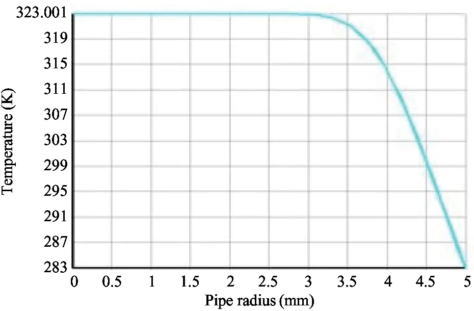
Fig.11 Temperature curve under R=5mm, L=40mm

Fig.12 Temperature distribution under R=5mm, L=200mm

Fig.13 Temperature curve under R=5mm, L=200mm

Fig.14 Temperature distribution under R=5mm, L=800mm
2.3 Influence of cold end temperature of semiconductor cooler TCon the outlet temperature
When the pipe radius R=5mm, the pressure difference ΔP=10Pa, the pipe length L=200mm, the inlet temperature TIN=323K, the cold end temperature TC=273K, outlet temperature distribution and outlet temperature curve are shown in Fig.16 and Fig.17.

Fig.15 Temperature curve under R=5mm, L=800mm

Fig.16 Temperature distribution under R=5mm, L=200mm, Tc=273K

Fig.17 Outlet temperature curve under R=5mm, L=200mm, Tc=273K
Comparing Fig.17 with Fig.13, it can be seen that in the same other condition situation, when the cold end temperature TC=273K and the colder end temperature TC=283K, the outlet temperature decreases by 2K. Although it also improves the cooling effect by reducing the cold end temperature, the ef-fect is not obvious. Thus it is not an effective method.
2.4 Influence of pipe radius R on the outlet temperature
When the pipe radius R=10mm, the pressure difference ΔP=10Pa, the inlet temperature TIN=323K, the cold end temperature TC=283K, temperature distribution and outlet temperature curve are shown in Fig.18~Fig.21.
From Fig.18 to Fig.21, it can be seen that the cooling effect of pipe radius R=10mm decreases obviously than R=5mm. When the pipe length increases to 800mm, the temperature difference is just 6.5K. It also needs to increase the pipe length for achieving the better cooling effect.

Fig.18 Outlet temperature distribution under R=10mm, L=200mm

Fig.19 Outlet temperature curve under R=10mm, L=200mm

Fig.20 Outlet temperature distribution under

Fig.21 Outlet temperature curve under R=10mm, L=800mm
Based on the above analysis, it can be seen that reducing the pipe pressure difference ΔP, increasing the pipe length L and reducing the cold end temperature TCcan lower the outlet temperature to achieve the oil cooling.
3 Experimental study of the constant temperature hydraulic tank cooling system
3.1 Design of the constant temperature hydraulic tank semiconductor cooler
By choosing an appropriate semiconductor chilling plate, heat absorbing element of the cold end, heat radiator of the hot end, insulation material and thermal conductivity aluminum and so on, the structure of a semiconductor cooler for a tank is designed, as shown in Fig.22.
3.2 Design of the constant temperature tank control system
The constant temperature hydraulic tank semiconductor refrigeration system is a control system with PLC as the core, and is shown in Fig.23.

1,8-Mounting screws 2- cold end heat exchanger 3-mounting flange 4-heat storage cold plate 5,6,7-thermal isolation foaming material of polyester ammonia 9-cold end heat exchanger 10-cooling fan of the hot end 11-Sest rubber 12-thermal conductivity aluminum 13-chilling plate 14-the fan installation panel
Fig.22 The structure of semiconductor cooler

Fig.23 The composition diagram of semiconductor refrigeration system
The system is mainly composed of temperature sensor, temperature controller, programmable logic controller (PLC), intermediate control circuit, and so on. The sensor detects the signal of hydraulic oil temperature; according to the detected signal, PLC can control the system to start and stop through the intermediate circuit; the controller can achieve hydraulic oil temperature constant.
3.3 Test for the constant temperature hydraulic tank cooling system
Heat is generated by the power loss of pump and overflow-valve. The specific method is: installing the O-function common valve with same specification in the position of original reversing valve, which is always in the middle position during the test, so that the oil flows back to the tank after a pump and overflow valve, the input power of pump is all transformed into heat, and the system’s calorific value can be adjusted by adjusting the overflow valve pressure. The semiconductor cooler will begin to work when the temperature of hydraulic oil exceeds the upper limit temperature of 38℃. The temperature of hydraulic oil is controlled at 37℃, and the test system is shown in Fig.24.

Fig.24 The test system of constant temperature tank
(1) The system pressure is 2MPa. After the system runs stably, the operating current of semiconductor cooler is 26A, and the heat sink’s temperature measured by portable thermometer is 29℃, the cold plate is 7℃ and ambient temperature is 12±2℃. By calculating, the gross system’s calorific value Phris 0.378kW, and the required cooling power Pzis 0.069kW. In the working situation, the system is tested, and the result is shown in Fig.25.
From the above diagram, it can be seen that the oil temperature is gradually rising with time in the case of the refrigerator not working, and then beyond the specified temperature range. After the refrigerator works, the temperature can gradually educe to the specified temperature range.
The hydraulic oil heating power is:
Ps=γ·C·V·ΔT/60 =1.97×0.863×111.6×0.29=55(W)
The hydraulic oil cooling power is:
Pj=γ·C·V·ΔT/60 =1.97×0.863×111.6×0.41=78(W)
By the above calculation, the actual power for heating is 55W, which is less than the calculated power 69W, the loss heat is mainly consumed by the pipe and valve. The refrigerator can lower effectively the temperature at the rate of 0.00041℃/s. Thus the actual cooling capacity which is calculated is 133W. The refrigeration coefficient is
(17)
It can be seen that actual cooling capacity is lower than the design capacity. The main reason is that the sealing of cold end is not enough.
(2) The system pressure is 2.5MPa. After the system runs stably, the heat sink’s temperature measured by portable thermometer is 29℃, the cold plate is 7℃, ambient temperature is 12±2℃. By calculating, the gross system’s calorific value Phris 0.472kW, and the required cooling power Pzis 0.168kW. The system is tested in the situation, and the result is shown in Fig.26.

Fig.26 Temperature curves
From the above diagram, it can be seen that the oil temperature rises gradually with time, and also beyond the specified temperature range under the condition of refrigerator doesn’t work. After the refrigerator works, the temperature can gradually reduce to the specified temperature range. However, the cooling speed is slower than the speed of system pressure 2MPa. The fact conforms to the theory and actual situation.
The hydraulic oil heating power is
Ps=γ·C·V·ΔT/60 =1.97×0.863×111.6×0.45=85(W)
The hydraulic oil cooling power is
Pj=γ·C·V·ΔT/60 =1.97×0.863×111.6×0.32=60(W)
As a result, there is great difference between the actual heating power 85W and the calculated power 168W. Loss heat is mainly consumed by the pipe and valve. The temperature can be lowered effectively at the rate of 0.00032℃/s by the refrigerator. Thus the actual cooling capacity is 145W, which is higher than the situation of the system pressure being 2MPa. The refrigeration coefficient is
(18)
The cooling capacity is increased when pressure of the system is increased, but the refrigeration coefficient is still small.
4 Conclusion
(1) The study proposes a new type of oil cooling method used in the hydraulic system. Semiconductor refrigeration technology is first applied to the hydraulic oil temperature control system, and it provides a new theoretical basis and engineering approach to solve the problem of the hydraulic oil temperature control.
(2) The heat transfer model for semiconductor cooler is established and simulated. It proposes the structure of pipe semiconductor cooler on the basis, and designs a semiconductor cooler for a tank.
(3) The application of semiconductor refrigeration technology in hydraulic system is realized, and the feasibility of the theory and design is verified. The test result indicates that, when the environment temperature is 12±2℃ and the initial oil temperature is 38℃, the cooling speed of system pressure 2MPa and 2.5MPa is 0.00041℃/s and 0.00032℃/s respectively. The oil temperature can gradually reduce to the specified temperature range, and verifies that the semiconductor refrigeration system meets the requirements of the oil temperature control.
[ 1] Riffat S B, Qiu G. Comparative investigation of thermoelectric air-conditioners versus vapour compression and absorption air-conditioners. Applied Thermal Engineering, 2004,24(14):1979-1993
[ 2] Choi H S, Yun S, Whang K. Development of a temperature-controlled car-seat system utilizing thermoelectric device. Applied Thermal Engineering, 2007,27(2):2841-2849
[ 3] Zhao X J, Cai Y X, Wang J, et al. Thermal model design and optimize of LED headlamp cooling device based on semiconductor refrigeration. Chinese Journal of Luminescence, 2014,35(10):1269-1275 (In Chinese)
[ 4] Zhang H W, Zhang L, Li K, et al. Temperature control system of high power semiconductor laser. Journal of Jilin University, 2005,45(5):642-644 (In Chinese)
[ 5] Zhang J B, Shao T G, Wang Y, et al. A new type of dehumidifier for enclosed high-voltage switchgear cabinet. TELKOMNIKA: Indonesian Journal of Electrical Engineering, 2013,10(7):102-110
[ 6] Chang Y W, Chang C. Thermoelectric air-cooling module for electronic Devices. Applied Thermal Engineering, 2013, (29):2731-2737
[ 7] Semeniouk V A, Pilipenko T V. Thermoelectric coolers with small resp-onse time. In: Proceedings of the 15th International Conference on Thermoelectrics, Pa-sadena, USA, 1996. 301-306
[ 8] Wang W, Wang S X. The design of temperature control system based on the Cortex-MO and thermoelectric cooling. China Instrumentation, 2011, (3):51-54 (In Chinese)
[ 9] Xu D S. Semiconductor Refrigeration and Application Technology. Shanghai: Shanghai Jiaotong University Press, 1992. 236 (In Chinese)
[10] Dai W H, Dai Y J, Zhang P, et al. Measurement for the characteristic parameters and selection of thermoelectric cooling modules. Journal of Shanghai Jiaotong University, 2004,38(10):1669-1672 (In Chinese)
Guo Rui, born in 1980. He is currently an associate professor in mechatronic engineering at Yanshan University, China. He received his Ph.D degree from the Department of Mechanical Engineering of Yanshan University, Qinhuangdao, China, in 2010.His research interests include innovative design and reliability of complex electromechanical products.
10.3772/j.issn.1006-6748.2016.04.013
① Supported by the National Natural Science Foundation of China (No. 51175448, 51405424)
② To whom correspondence should be addressed. E-mail: guorui@ysu.edu.cn Received on June 16, 2015
 High Technology Letters2016年4期
- High Technology Letters的其它文章
- Clustering approach based on hierarchical expansion for community detection of scientific collaboration network①
- Integration of naval distributed tactical training simulation system based on advanced message queuing protocol①
- A visual awareness pathway in cognitive model ABGP①
- Measurements and analysis at 400MHz and 2600MHz in corridor radio channel①
- Fluid simulation of internal leakage for continuous rotary electro-hydraulic servo motor①
- Fuzzy image restoration using modulation transfer function①