
Optimization and control of a reactive distillation process for the synthesis of dimethyl carbonate☆
2017-05-29 10:48ZhixianHuangYixiongLinXiaodaWangChangshenYeLingLi
Zhixian Huang,Yixiong Lin,Xiaoda Wang,Changshen Ye,Ling Li*
School of Chemical Engineering,Fuzhou University,Fuzhou 350116,China
1.Introduction
Dimethyl carbonate(DMC)is an environmentally benign and biodegradable chemical,and ithas been widely used in the chemistry industry as a substitute to replace dimethyl sulfate and methyl halides in methylation reactions,or as a carbonylation agentin carbonylation reactions[1].In addition,DMC also has been used an additive to fuel because of its high oxygen content and octane number[2].So DMC has attracted substantialresearch efforts in recentyears.There are severalways to prepare DMC,such as the methanolysis of urea[3]and direct synthesis of DMC from propylene carbonate(PC)and methanol(MeOH)[4].However,urea methanolysis to DMC suffers from some problems including low production selectivity and high molar ratio of methanol to urea[5].Although the directproduction ofDMC by reacting PC and MeOHis limited by the unfavorable equilibriumconstant,a high conversion ofPC stillcan be achieved by using reactive distillation method,because reaction products can be removed continuously from the reactive zone and thus conversion can be increased far beyond whatis expected by the equilibrium.In the transesterification reaction of ethyl carbonate and methanol,the recent papers by Fang and Xiao[6]and Hsuet al.[7]reported that the completion conversion of the limiting reactant could be achieved by using reactive distillation.
But in the transesterification reaction of PC and MeOH,the products are DMC and propylene glycol(PG).The former can form a homogeneous azeotrope with the reactant MeOH,so the overhead of the reactive distillation column will be a dimethyl carbonate and methanol mixture that is a challenge for the purification of dimethyl carbonate.Therefore,further separation of the mixture DMC and MeOH is needed.In order to break the dimethyl carbonate and methanol azeotrope,several techniques have been proposed,such as adsorption separation[8],extractive distillation[5,7,9],low temperature crystallization[10],pressure swing distillation[11,12],and membrane pervaporation[13,14].Among these methods,pressure swing distillation is considered as one ofthe mosteffective and environmentalfriendly processes.The dynamic simulation and control of pressure swing distillation systems for separating azeotropes have been investigated and evaluated in a lot of research papers[15–19].Weiet al.explored the pressure swing distillation systems for separation of DMC/MeOH and proposed an optimized separation con figuration based on the global economic analysis[12].Liet al.simulated and analyzed the process of separation of DMC and MeOH,including a high-pressure distillation column and an atmospheric distillation column in series[20].
In our previous works,the integration of the reactive distillation and the separation ofthe DMC/MeOHmixture were investigated,and a novel energy saving process for the synthesis of DMC was proposed[21].This new process with a reactive distillation column and a high-pressure distillation column can save energy by 29.50%compared with the traditional process.However,the feed molar ratio of MeOH to PC is much higher than thatofstoichiometric ratio in the transesterification reaction,which meansthatmore energy isrequired to recoverexcess methanol.Furthermore,the dynamic characteristic ofthis process hasn'tbeen investigated.
In this paper,optimization and control of the procedure for the synthesis of dimethyl carbonate by reactive distillation were carried out.First,the optimal flowsheetwas obtained by minimizing the totalannual cost(TAC)of the system.Then,the control strategy of this process with heat integrated was explored and its required control performance was discussed through varying feed flow rate and feed composition.
2.Reaction Kinetic and Thermodynamic Model
2.1.Reaction kinetic
The transesterification ofPCwith MeOH,using homogeneous or heterogeneous catalysts,has already been investigated[6,22,23].Even though many catalysts are suitable for this reaction,sodium methoxide is stilla promising candidate in the currentindustrialapplication since it possesses higher activity compared with other catalysts.Moreover,its reaction temperature is relatively mild.The liquid-phase reversible transesterification reaction considered is.

The kinetics for the forward and reverse reactions catalyzed by sodium methoxide are based on those given by Zhang[22].
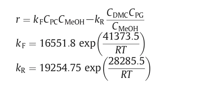
whereris the reaction rate of PC(mol·L-1·min-1),Ciis the concentration of theicomponent(mol·L-1),Ris gas constant(J·mol-1·K-1),andTis temperature(K).
2.2.Thermodynamic model
The phase equilibrium of this reaction system is complex due to the existence of a binary azeotrope mixture of DMC and MeOH.In order to accurately describe the phase equilibriums of the system,UNIQUAC model is used and its parameters are obtained to fit the vapor–liquid data.The experimental data for the pair of MeOH/DMC were obtained from literatures[24].The vapor–liquid equilibrium data for the pairs of DMC/PC and DMC/PG were obtained from literature[25].The model parameters of MEOH/PG and all other physical properties were obtained directly from Aspen Plus.Table 1 summarizes the UNIQUAC binary interaction parameters used in the simulation.The calculated boiling points of pure components and azeotropic compositions by using UNIQUAC model are presented in Tables 2 and 3,respectively,which indicates that the UNIQUAC model is suitable for this system.
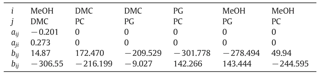
Table 1UNIQUAC model parameters for the DMC process

Table 2Boiling points of pure components at atmospheric pressure
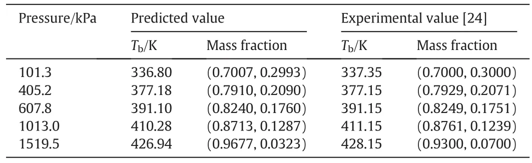
Table 3Comparisons of predicted and experimental azeotrope for MeOH/DMC at different pressures
3.Steady-state Optimization
3.1.Reactive distillation process
The process for the production of DMC by reactive distillation is shown in Fig.1.In this flowsheet,the reactant PC(stream F1)is fed into the top part of the reaction section,and the fresh MeOH(stream F2)and a recycled stream rich in MeOH are fed into the bottom and middle of the reaction section,respectively.The top productof the reactive distillation(RD)column is a mixture of product DMC and unreacted MeOH,while co-productpropylene glycolleaves outthe bottom of the RD column.The distillate of the RD column is fed into the high pressure(HP)column,which produces high-purity DMC in the bottoms and a distillate stream whose composition is near that of the azeotrope.The distillate(stream R1)is recycled back to the RD column.Due to the very low catalyst concentration(about 0.15 wt%),the catalyst component was ignored in the simulation for simplification.
Based on the industrial data provided by Feiyang Chemical Co.,Ltd.(in China),a detail simulation was performed in our previous study[21].The results indicate that the proposed process is feasible for the synthesis of DMC.However,the feed molar ratio of MeOH to PC(≈5.6:1)is much higher than that of stoichiometric ratio in the transesterification reaction and the PC conversion is not very high(about 96.5%),which means that more energy is required to further purify the co-product PG and recover excess methanol.Hence,in this study the feed molar ratio will be optimized while ensuring the desired PC conversion rate of 99.9%and the desired DMC purity of 99.5 mass%.Since the solubility of sodium methylate in the PC or PG is relative low,sodium methylate is dissolved in the methanol firstly and then is introduced into the RD column with PC.To avoid clogging pipes or internals in the RD column due to the crystallization of the sodium methylate,the mass concentration of MeOH in the fresh PC feed is another constrain.
There are many design variables needed to be optimized in this process.In the RD column,such design variables involve the total number oftrays(NRD),PC feed location(NF1),MeOHfeed location(NF2),and recycle streamfeed location(NFR).For the HP column,the totalnumber of trays(NHP)and the feed location(NFHP)also need to be optimized.Moreover,the operating pressure is an important process parameter for the distillation system.Zhanget al.found that the transesterification of PC and MeOH is an exothermic reaction and the optimum reaction temperature ranges from 333.2 to 341.2 K [22].And the transesterification reaction mainly takes place on the 5th stage(as shown in Fig.4).When the RDcolumn is operating atatmospheric pressure,the temperature on the 5th stage is 339.2 K.So the RD column is operating at atmospheric pressure in this work.Note that all produced dimethyl carbonate that leaves the reactive section zone goes at the top of the RD column with the methanol.And the HP column that is used to separate dimethyl carbonate from methanol produces highpurity dimethyl carbonate in the bottom and produces a distillate that has a composition near the azeotropic composition.The composition of the azeotrope(DMC/MeOH)varies with the change of pressure.If the HP column is operating at high pressure,the methanol recycled back to the RD column would have a less concentration of DMC.This would reduce theflow rate ofthe recycle streamand hence significantly reduce energy consumption.However,the disadvantage in operating at high pressure is a high base temperature.Considering the heating utility(1.8 MPa steam)and the minimum temperature difference in the heat transfer(ΔT=20 K),the 1.1 MPa pressure seems to be about the optimum because going above this pressure does notshiftthe azeotrope significantly and raises the base temperature.
In order to achieve the economic optimization of the distillation column system,total annual cost(TAC)is usually used.The TAC is defined as follows:


Fig.1.The optimized flowsheet for the production of DMC.
The main pieces of equipment of the distillation column system are column vessels(high and diameter)and two heat exchangers(condenser and reboiler).Since the costs of the vessels and heat exchangers are usually greatly more than the costs of auxiliary items such as pumps,pipes,valves and the reflux drums,auxiliary items are not considered in the optimization of the columns[26].Thus,the sum of the column vessel capital cost and the heat exchanger cost is the capital cost.The parameters for evaluating the cost of equipment and energy cost are shown in Table 4[27].
3.2.Flowsheet convergence
Because stream R1,containing MeOH and DMC,is recycled back to the RD column,it is not easy to estimate reasonable distillate flow rate for both the RD and HP columns.As we all know,when recycle streams are present,the convergence of steady-state simulators becomes very difficult.To ensure the convergence of the simulation,the distillate of the RD column and the HP column must be estimated in advance.In order to solve such a complicated matter,therefore,a simple and effective method based on the mass balance is proposed.

Table 4Basis of economics
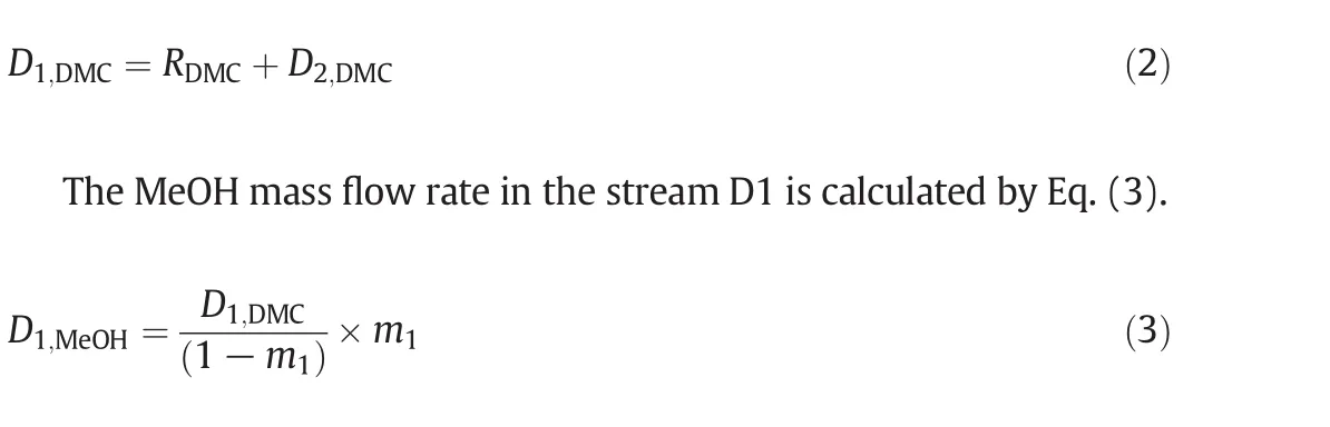
For the RD column,DMC leaving the RD column is the sum of the DMC formed in the transesterification reactionRDMCand the DMC in the recycle streamD2,DMC.
wherem1is the mass composition of MeOH in the azeotropic mixture(DMC and MeOH)under the atmospheric pressure.
According to the purity of the product DMC,the amount of MeOH in the distillate of the HP column,D2,MeOH,is estimated by Eq.(4).
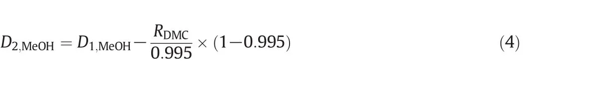
In the same way,D2,DMCis estimated by Eq.(5).

wherem2is the mass composition of MeOH in the recycle stream.
Thus,the procedure to estimate the flow rate of the recycle stream between the RD and HP columns is described as follows:
(1)Give the mass composition of MeOH in the recycle stream(m2)and supposeD2,DMCis equal to 0.
(2)The amountofDMC in the distillate ofthe RDcolumn is computed with Eq.(2).
(3)The amountofMeOHin the distillate ofthe RDcolumn is calculated using Eq.(3).
(4)The mass flow rate of the recycle stream is calculated with Eqs.(4)and(5).
(5)Go back to the step 2,repeat steps(2)–(4)until the calculated values(D2,DMCorD2,MeOH)remain unchanged.
Once the values ofD1,DMC,D2,DMC,D2,DMC,andD2,MeOHare determined,the distillates of the RD column and the HP column(D1andD2)are easy to be obtained.
3.3.Optimization
Note that the variablem2is the most sensitive design variable in terms of TAC optimization,because it determines the amount of the recycle stream and the difficulty of separating in the HP column and thus affects the energy consumption of the entire system.So,the optimization ofm2was set at the outmost iterative loop.Another issue that needs to be addressed is that during each simulation run the holdup in the reactive tray must be iteratively estimated to consist with the one obtained from the tray sizing calculation.The detail optimization procedure is presented in Fig.2.
By using above iterative optimization procedure,the values of the design variables were found:feed location of the RD column,total stages ofthe RDcolumn,feed location ofthe HP column,and totalstages of the HP column.The effects of variables on TAC are displayed in Figs.3 and 4.Because the overhead vapor at the top of the HP column can be used as the heat source of the reboiler of the RD column,the TAC of the RD column does not include energy cost and reboiler cost and thus is significantly lower than the TAC of the HP column(Table 5).The resulting optimal flow sheet with flow and composition is shown in Figs.1 and 5 shows component generation amounts pro file in the RD column,and the corresponding temperature and vapor composition pro files are presented in Fig.6.Note that the feed molar ratio of MeOH to PC is 2.61:1 and close to stoichiometric ratio in the transesterification reaction.The conversion ofPC underoptimalconditions reached as high as 99.9%and energy saving of 18.6%was achieved compared to the result given in the literature[21].
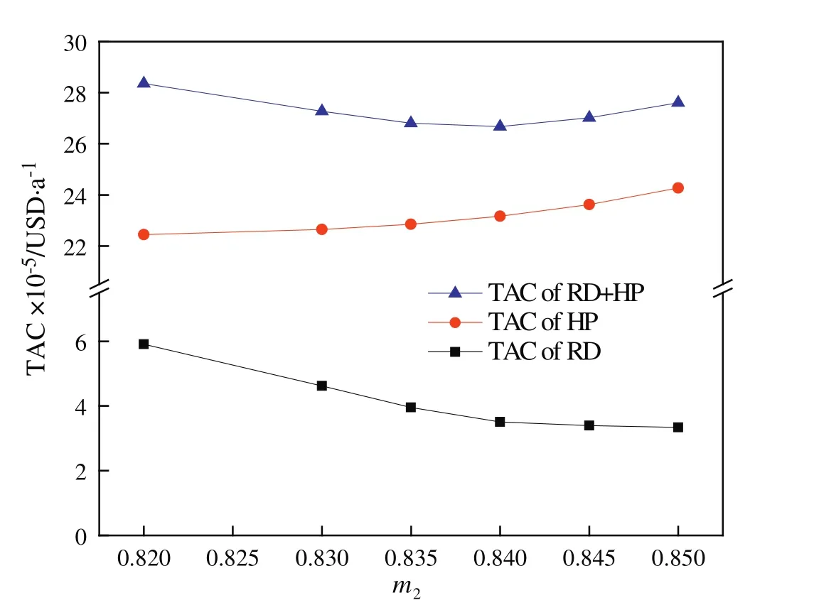
Fig.3.Effect of the MeOH composition(m2)in the recycle stream on the TAC.

Fig.2.Sequential iterative optimization produce.

Fig.4.Relationship between TAC and design variables:(a)RD and(b)HP column.

Table 5Column specifications for original and optimal designs
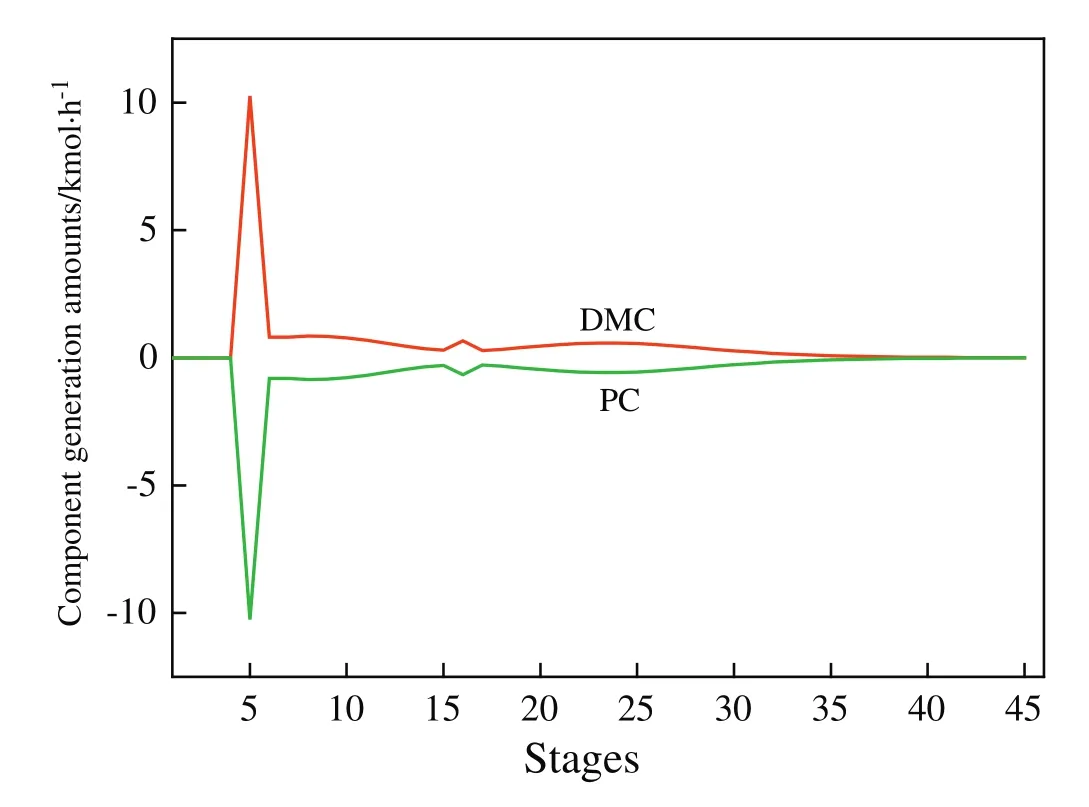
Fig.5.Component generation amount pro file in the RD column.
4.Overall Control Strategies
In the following,the proper overallcontrolstrategy ofthe process for the production of DMC will be investigated.Aspen Dynamics was used for the control study.Before the Aspen Plus steady state simulation was exported to Aspen Dynamics as a pressure-driven simulation,all the pumps and control valves needed in the process should be added and the volume of vessels should be determined.So,the tray-sizing function in Aspen Plus was used to calculate the size of the RD column and the HP column.The sizes of the reflux drum and the sump were determined by using heuristic methods recommended by Luyben[28]:all are sized to provide 5 min of holdup when at 50%level.The pressure drops inside both the RDcolumn and the HP column were automatically calculated in Aspen Dynamics to accountforliquid hydraulics and vapor traffic.
The main control objective is to maintain the conversion of PC(≥99.9%)and the DMC product specification(≥99.5%mass).The overall control strategies of this system will be developed in order to hold above specifications in spite of the fluctuations of feed flow and feed composition that frequently exist in the practical processes.Since temperature control is usually used instead of composition control in chemical industrial applications,temperature control is preferred in the control strategy development.
4.1.Inventory control
In this system,there are twelve control degrees of freedom:PC feed flow,MeOH feed flow,RD reboiler duty,RD bottom flow,RD distillate,RD reflux,RD condenser duty,HP bottom flow,HP reboiler duty,HP distillate,HP reflux,and HP condenserduty.In orderto keep the totalmaterial balance,eight degrees of freedom are used for the inventory control loops.That is,the reflux drum levels of the RD column and the HP column are controlled by manipulating their distillate flows,while base levels of the columns are controlled by manipulating the corresponding bottom flow rates.The pressures of both condensers are controlled by manipulating the condenser duties.Fresh PC feed(stream F1)is flow controlled and used as a throughput manipulator to change its set point when production rate changes are needed.The total MeOH feed is flow controlled by manipulating a control valve at fresh feed stream while the set point of this flow control loop is adjusted to maintain suitable MeOH/PC feed ratio into the RD column.This set point can be reset by other controller,which willbe discussed detailin nextchapter.Forthe control loops of the flow rate,pressure,and liquid level,their controller parameters are con figured by empirical values as shown in Table 6.
4.2.Quality control loops
The remaining manipulated variables include reflux flows and reboiler duties.In the HP column,the reflux flow rate is controlled byR/Dratio.It is important to select a sensitive tray location for temperature control.The steady state temperature pro files of both columns are presented in Fig.6.In the HP column,the location where temperature changes rapidly from tray to tray is around tray 40,so the temperature on this tray is controlled by reboiler heat input.In order to improve the dynamic performance of the control loop,a“T40C”controller is on “cascade”with the “QR/F”ratio.The output value from the“T40C”controller is the ratio of reboiler heat input in the HP column to the distillate of the RD column.However,in the RD column there is a moderate change in temperatures from tray to tray.Therefore,a more sensitive tray temperature should be selected as controlled variable.In this work,sensitivity analyses were performed on the RD column.To determine the steady state gains of tray temperature in the linear region,small changes in the design value(PC feed flow rate±10%and reboiler heat duty±0.5%)were carried out.Results are displayed in Fig.7.For the disturbances of PC feed flow rate,there are two symmetrical peaks of temperature change on the 5th and 25th trays,while only one symmetrical peak of temperature change on the 5th tray when the disturbances of reboiler heat duty are introduced.So,the 5th tray was considered as a temperature control tray.
A suitable feed ratio between the reactants must be maintained when operating a reactive distillation column.Feed ratio control is the simplest way to maintain stoichiometric balance.But PC feed(F1 stream)contains MeOH,so “Multiply”control model in Aspen Dynamic cannot be used directly in this case.Furthermore,MeOH feed must ensure that there is sufficient MeOH concentration in the bottom of the RD column.In order to satisfy the above requirements,a temperature/flow rate cascade control structure is explored,and the tray selected for temperature controlis located in the bottom where the temperature changes quickly.Fig.9(a)shows that the set point of the MeOH flow controller is adjusted by the output of the temperature controllers(T45C)in the RD column.
In addition,note that the temperature difference(ΔT)between the condenser of the HP column and the base of the RD column is quite large(413.6–370.9=42.7 K)and the reboiler heat input of the RD column,Qr=5.57 MW,is lowerthan the condenserheatremovalofthe HP column,Qc=5.95 MW.Therefore,the overhead vaporin the HPcolumn can be used as the heat source of the reboiler of the RD column,and the excess heat in the condenser in the HP column is removed by an auxiliary condenser.Here,assuming that the heat-transfer area of the condenser/reboiler is 229.8 m2and the overall heat-transfer coefficientUis 0.002045 GJ·(h·m2·K)-1,the heat duty of the auxiliary condenser,0.38 MW,can be determined.In this way,the temperature on the 5th tray in the RD column is controlled by manipulating the reflux.The set point of this T5temperature controller is 339.2 K.Supposing there is a 1 min time delay in the temperature measurement,close loop relay-feedback testing and Tyreus–Luyben tuning yields the tuning parameters(Kc=28.08,τ=7.92 min).And the auxiliary condenser duty can be manipulated to control the operating pressure of the HP column.Implementing this structure in Aspen Dynamics requires“ flowsheet equations”as shown in Fig.8.Fig.9(a)gives the plantwide control structure(CS1)and their set points are displayed in Fig.9(b).

Fig.6.Temperature and liquid composition pro file in(a)the RD column and(b)the HP column.
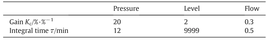
Table 6Conventional PI controller parameter
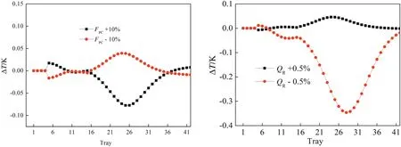
Fig.7.Sensitive analysis of the RD column.
4.3.Closed-loop simulation results of CS1
The control performance is tested for feed flow disturbance.Fig.10 gives dynamic response for the control structure under-10%PC feed flow rate disturbance.It is found the control structure performs nicely in holding high purity of DMC product and conversion of the PC.However,when+10%PC feed flow disturbance is introduced at 2 h,the conversion of PC decreases sharply and the system goes wrong after running 4.5 h.
Usually when the feed rate is increased,the reboiler heat duty should increase.In this control system,however,increasing PC feed flow rate produces an immediate decrease in the distillate from the RD column as expected.The temperature on the 40th tray in the HP column willincrease as the feed is decreased(as shown in Fig.11).Because the temperature on the 40th tray is controlled by the reboilerheatinput and the temperature controller is “reverse acting”,an increase in temperature should cause the controller to decrease the required heat duty of the reboiler.Since the heat duty of the condenser/reboiler depends on the product of ΔT,the heat transfer area,and the overall heat-transfer coefficient,decreasing the reboiler heat input in the HP column should produce a decrease in operating pressure in the HP column and thus overhead temperature,which in turn leads to a reduction in reboiler heatduty in the RDcolumn.Therefore,the interaction among these factors makes the system gradually deviate from the normal operating state.So an improved control strategy is required to provide a correct adjustment in reboiler heat input.
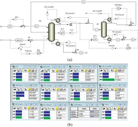
Fig.9.(a)Control strategy(CS1)for partially heat-integrated process.(b)Controller faceplates.
4.4.Improved control structure
Fig.12(a)displays the improved controlstructure CS2.Itonly differs from the CS1 structure in the following aspects:(1)the reflux flow rate in the RD column is controlled byR/Dratio;(2)the temperature on the 5th tray in the RD column is controlled by manipulating the reboiler heatinputto the HP column;and(3)in the HP column the temperature on the 40th tray is controlled by manipulating the reflux flow rate.All the controllers are retuned and tuning parameters are presented in Table 7.

Fig.12.(a)Control strategy(CS2)for partially heat-integrated process.(b)Controller faceplates.

Table 7Controller tuning parameters for control structure CS1 and CS2
Fig.13 gives dynamic responses for the control structure under±10%PC feed flow rate disturbances,whilefig.14 for±10%PC feed composition disturbances.The solid blue line demonstrates the response for negative step changes,while the dashed red line shows the response for positive step changes.Both the disturbances are introduced at2 h.Itis observed that CS2 can adjustthe MeOH feed to accommodate PC changes,as was desired.Except for T5in the RD column which shows a small deviation from its base case value,both T45in the RD column and T40in the HP column returned to their set point values.The responses of PC conversion show asymmetric behavior for positive and negative PC feed composition disturbances but meet the design requirement.In addition,both DMC product composition in the HP column and MeOH composition in the bottom of the RD column also meet their corresponding specifications.The above results demonstrate that the proposed temperature controls can maintain product quality and provide a robust operation.
5.Conclusions
Dimethyl carbonate is an environmentally benign and biodegradable chemical.A novel process including a RD column with an excess of reactant MeOH and a high-pressure distillation column is used to obtain high PC reaction conversion and high purity dimethyl carbonate product.The optimal process is determined by minimizing the total TAC.To estimate the flow rate and composition of the recycle stream in a pressure-swing distillation system,a simple and effective method is proposed and adopted in the process optimization.The optimization results show that the feed molar ratio of MeOH to PC is 2.61:1 and close to stoichiometric ratio in the transesterification reaction,and the modification process can save energy consumption by 18.6%with the propylene carbonate conversion of 99.9%.
Dynamic simulation results illustrate that the temperature/ flow rate cascade control plus with simple temperature control can keep not only productpurity butalso conversion ofthe reactantattheirdesired values in the face of the disturbances in reactant feed flow and feed composition.

Fig.13.Dynamic responses under±10%PC feed flow rate disturbances.
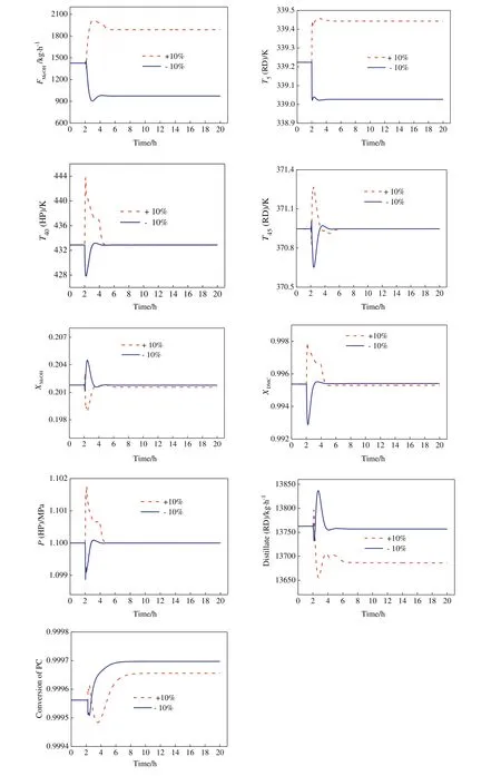
Fig.14.Dynamic responses under±10%PC composition disturbances.
[1]S.J.Wang,C.C.Yu,H.P.Huang,Plant-wide design and control of DMC synthesis process via reactive distillation and thermally coupled extractive distillation,Comput.Chem.Eng.34(2010)361–373.
[2]T.J.Bruno,A.Wolk,A.Naydich,M.L.Huber,Composition-explicit distillation curves for mixtures of diesel fuel with dimethyl carbonate and diethyl carbonate,Energy Fuel23(2009)3989–3997.
[3]B.Yang,D.Wang,H.Y.Lin,J.Sun,X.P.Wang,Synthesis of dimethyl carbonate from urea and methanol catalyzed by the metallic compounds at atmospheric pressure,Catal.Commun.7(2006)472–477.
[4]P.Kumar,V.Srivastava,I.Mishra,Dimethyl carbonate synthesis from propylene carbonate with methanol using Cu–Zn–Al catalyst,Energy Fuel29(2015)2664–2675.
[5]H.Matsuda,H.Takahara,S.Fujino,et al.,Selection of entrainers for the separation of the binary azeotropic system methanol+dimethyl carbonate by extractive distillation,Fluid Phase Equilib.310(2011)166–181.
[6]Y.Fang,W.Xiao,Experimental and modeling studies on a homogeneous reactive distillation system for dimethyl carbonate synthesis by transesterification,Sep.Purif.Technol.34(2004)255–263.
[7]K.Y.Hsu,Y.C.Hsiao,I.L.Chien,Design and control of dimethyl carbonate–methanol separation via extractive distillation in the dimethyl carbonate reactive distillation process,Ind.Eng.Chem.Res.49(2010)735–749.
[8]W.Fan,X.Wang,W.Li,W.Xiao,Adsorption separation of dimethyl carbonate and methanol azeotrope,Chem.Eng.38(2010)10–13.
[9]X.Li,Y.Lian,Z.Zhang,Q.Jia,Separation of dimethylcarbonate–methanol mixture by extractive distillation,Chem.Eng.40(2012)14–25.
[10]M.A.Pacheco,C.L.Marshall,Review of dimethyl carbonate manufacture and its characteristics as a fuel additive,Energy Fuel11(1997)2–29.
[11]J.U.Repke,F.Forner,A.Klein,Separation of homogeneous azeotropic mixtures by pressure swing distillation,Chem.Eng.Technol.28(2005)1151–1157.
[12]H.M.Wei,F.Wang,J.L.Zhang,et al.,Design and control of dimethyl carbonate–methanol separation via pressure-swing distillation,Ind.Eng.Chem.Res.52(2013)11463–11478.
[13]W.Won,X.Feng,L.Darren,Separation of dimethyl carbonate/methanol/water mixtures by pervaporation using crosslinked chitosan membranes,Sep.Purif.Technol.31(2003)129–140.
[14]W.Won,X.Feng,L.Darren,Pervaporation with chitosan membranes:Separation of dimethyl carbonate/methanol/water mixtures,J.Membr.Sci.29(2002)493–508.
[15]J.U.Repke,A.Klein,D.Bogle,G.Wozny,Pressure swing batch distillation for homogeneous azeotropic separation,Chem.Eng.Res.Des.85(2007)492–501.
[16]G.Modla,P.Lang,Feasibility of new pressure swing batch distillation methods,Chem.Eng.Sci.63(2008)2856–2874.
[17]P.Varbanov,A.Klein,J.U.Repke,G.Wozny,Minimising the startup duration for mass-and heat-integrated two-column distillation systems:a conceptual approach,Chem.Eng.Prog.47(2008)24–56.
[18]W.L.Luyben,Design and control of a fully heat-integrated pressure-swing azeotropic distillation system,Ind.Eng.Chem.Res.47(2008)2681–2695.
[19]W.L.Luyben,Pressure-swing distillation for minimum-and maximum-boiling homogeneous azeotropes,Ind.Eng.Chem.Res.51(2012)10881–10886.
[20]C.Li,X.Zhang,S.Zhang,Q.Xu,Vapor–liquid equilibria and process simulation for separation of dimethyl carbonate and methanol azeotropic system,Chin.J.Process.Eng.3(2003)453–458.
[21]Z.X.Huang,J.L.Li,L.Y.Wang,et al.,Novel procedure for the synthesis of dimethyl carbonate by reactive distillation,Ind.Eng.Chem.Res.7(2014)3321–3328.
[22]S.Zhang,Y.Luo,Studies on the kinetics and technological conditions ofthe synthesis of dimethyl carbonate,Chem.React.Eng.Technol.1(1991)10–19.
[23]J.Holtbruegge,M.Leimbrink,P.Lutze,A.Górak,Synthesis of dimethyl carbonate and propylene glycol by transesterification of propylene carbonate with methanol:catalyst screening,chemical equilibrium and reaction kinetics,Chem.Eng.Sci.104(2013)347–360.
[24]Y.Shi,H.Liu,K.Wang,et al.,Measurements of isothermal vapor–liquid equilibrium of binary methanol/dimethyl carbonate system under pressure,Fluid Phase Equilib.23(2005)1–10.
[25]H.Luo,J.Zhou,W.Xiao,K.Zhu,Isobaric vapor–liquid equilibria of alkyl carbonates with alcohols,Fluid Phase Equilib.175(2000)91–105.
[26]W.L.Luyben,Comparison of pressure swing and extractive distillation methods for methanol recovery systems in the TAME reactive distillation process,Ind.Eng.Chem.Res.44(2005)5715–5725.
[27]W.L.Luyben,Principles and Case Studies of Simultaneous Design,Wiley&Sons Inc.,New Jersey,2011.
[28]W.L.Luyben,Design and control of the ethyl benzene process,AIChE J.57(2011)655–670.
 Chinese Journal of Chemical Engineering2017年8期
- Chinese Journal of Chemical Engineering的其它文章
- Optimal design of heat exchanger header for coal gasification in supercritical water through CFD simulations☆
- Integration strategies of hydrogen network in a refinery based on operational optimization of hydrotreating units☆
- Application of the dividing wall column to olefin separation influidization methanol to propylene(FMTP)process☆
- Coupled simulation of recirculation zonal firebox model and detailed kinetic reactor model in an industrial ethylene cracking furnace☆
- A systematic strategy for multi-period heat exchanger network retro fit under multiple practical restrictions☆
- Performance of CO2 absorption in a diameter-varying spray tower☆