
Coupled simulation of recirculation zonal firebox model and detailed kinetic reactor model in an industrial ethylene cracking furnace☆
2017-05-29 10:48ZhouFangTongQiuWeiguoZhou
Zhou Fang,Tong Qiu*,Weiguo Zhou
Department of Chemical Engineering,Tsinghua University,Beijing 100084,China
1.Introduction
Tubular furnaces have been widely applied in the petrochemical industry,especially in pyrolysis of hydrocarbons for production of olefins.In cracking process,the combustion of fuel gas in furnace transfers heat to support cracking reactions inside the tubular coil.Considering the complexity of the cracking process,accurate predictive simulation models of both firebox and reactor are required to obtain better furnace designs and industrial online operation optimization.Heynderickxet al.[1]and Detemmerman and Froment[2]were first to combine the zone method for radiation model and Computational Fluid Dynamics(CFD)method for firebox heat transfer simulation in the furnace.Huet al.[3]and Lanet al.[4]implemented a CFD numerical method to perform coupled simulation studies on the flow,combustion,radiative heat transfer,and thermal cracking reaction processes in the furnace.Niaeiet al.[5]performed simulations combining the zone method and the detailed pyrolysis reactions in an industrialplant.These coupled pyrolysis simulation models are based on both firebox simulation and tubular-coil simulation which guarantees the accuracy of ethylene cracking simulation.
To model the fireboxes and their combustors,the CFD approach has been widely researched,including Stefanidiset al.[6,7],Habibiet al.[8],and Huet al.[9].Because of continual improvements in CFD software and rapid increases in computationalpower,the CFDmodelhas become more accurate and can provide a quantitative understanding of turbulent flow and heattransferin such processes.However,there are further obstacles in the real industrial application,which arise from the geometrical complexity,such as multi-burner furnaces and uncertainties in boundary conditions[10].Another traditional limitation of CFD in industrial applications is that the calculation scale makes CFD simulations computationally intensive.In industrial simulation,especially coupled models,zone partitioning in the CFDmodelis too complicated forindustrial process and not appropriate for application in a one-dimensional plug- flow model of tubular reactor.
To overcome the disadvantages of the CFD method,Niaeiet al.[5]and Batu and Selcuk[11]established a three-dimensional model simulating firebox heat transfer based on the zone method.This method originally introduced by Hottel and Cohen[12]has become widely used over the past decades in modeling radiative heat transfer in firebox.Because the calculation of the directional exchange areas(DEAs)with multi-dimensional integrals[13–15]is the most time consuming part of the zone method,most developments of such methods focus on the calculation of the DEAs[16]and the matrix inversion which is needed in calculation of the total exchange areas(TEAs).Although some suitable zone methods have been constructed and used in industry-related simulations,there are several computational challenges in the zone method:a larger number of zones need to be generated to increase the accuracy of the zone method[17],an extra interpolation is required for turning the discrete results that the zone method produces into continuous results.In addition,obtaining correct flow field is another challenge in the radiation model(both the CFD model and the zone method).Hence if the zone method is applied to simulate heattransferin thefirebox,constructing an economicaland reliable flow field estimation method is important especially in industrial online simulation.
The simulation of tubular reactor plays a very important role in the coupled model as well.The priority in a reactor model is the reaction schemes and kinetics because of the complexity of the reaction mechanism,which influences the accuracy of product estimation.Over the past decades,three types of models:empirical[18],global[19],and detailed kinetic model[20]have been implemented in pyrolysis reaction simulations of tubular reactor coils.Both empirical and global models do not consider the detailed reaction interaction during cracking in the reactor coils and hence cannot meet the industrial demands for detailed analysis.The detailed kinetic modelused in this study constructs a detailed radicalreaction network with over 140 molecules which meets requirement for the detailed composition information management[21].
With models of firebox and tubular reactor,the product yield of naphtha pyrolysis and process data of the furnace can be calculated.Because the reactor model is a one-dimensional simulation process,this paper employs a two-dimensional data-based recirculation zonal modeling to decrease the firebox calculation scale which raises the calculation speed of coupled steam cracking simulation.The traditional zone method with adjusted Monte-Carlo integration[22]is used to modeland simulate radiation aspects ofan industrialfurnace.Considering the recirculation phenomenon in the flow field,a data-based recirculation zone model is implemented to enhance the accuracy of theflow field simulation.The recirculation zone model estimates the flow field using the industrial data(manufacturer's design data and the plant-measured data).On the one hand,the coupled model enables temperatures and flow field data in the firebox to be obtained.On the other hand,the calculated heat flux to the reactor enables product yield to be determined.The increase in these process data acquisitions contributesto fastindustrialsimulations and optimizations.The simulation model is coded in C++and the program is running on a personal computerwith Intelcore i7 which shows notonly the computation time of the whole process is less enough but also the accuracy is acceptable for the industrial simulation.
2.Firebox Mathematical Model and Numerical Method
To simulate the heattransfer ofthefirebox,a two-dimensionalrecirculation system has been constructed based on the zone method[23]which integrates combustion,radiation,convection,and flow models.The whole space of the firebox is split into zones and the enclosure walls are divided into finite surface zones.The temperature and properties within the volume and surface zones are uniform.By stipulating energy balance equations for all surface and volume zones,we can solve a system of nonlinear equations for the temperature field in all zones and the heat flux on the side walls of the enclosures.The heat flux pro file along the tube length is estimated by the cubic spline interpolation and gives the flux transferred to the tubular reactor.
2.1.Combustion model
In this study,the combustion inside the firebox is assumed to be a premixed gas complete without CO production.It can be modeled using the Roesler combustion model[24]expressed as:

The flame height in the firebox can be measured by the infrared thermometer or based on the export experience.
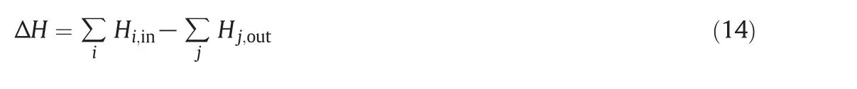
The combustion heat released between adjacent cross-sections of the firebox is calculated from

2.2.Convection model
The convection heat transfer occurs between volume zones and adjacent surface zones and calculated using

2.3.Radiation model
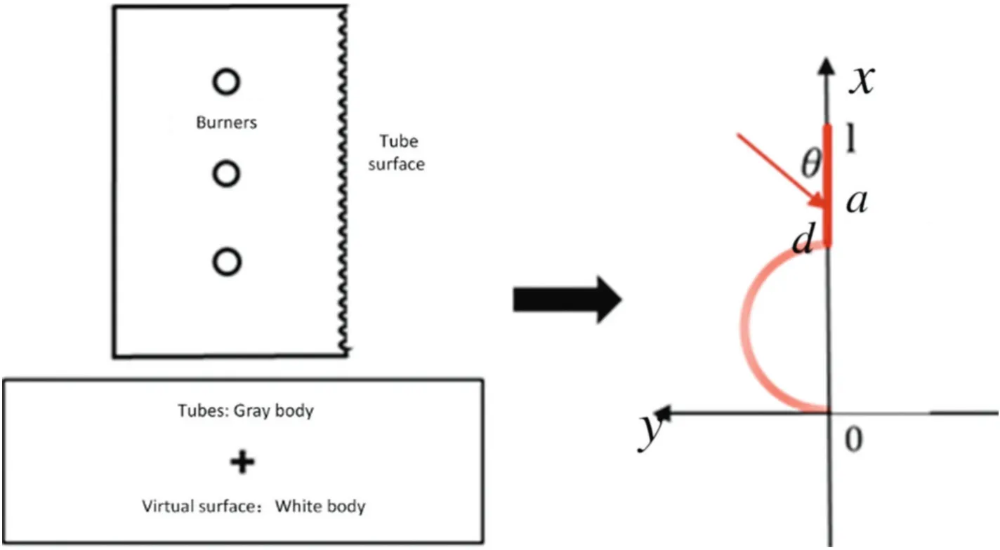
As the temperature of the flue gas in the firebox is high,radiation plays the dominant role in heat transfer.To estimate this transfer,the zone method including the weighted-sum-of-gray-gases model(WSGGM)[25,26]is implemented.The DEAs are calculated using AMCI[22];the TEAs are evaluated from matrix relations.The directed flux areas(DFAs)with WSGGM are then assessed using TEAs and account for the effects of surface emissivity and the non-gray behavior of radiant interchange.Based on these DFAs,the radiation heat transfer condition between zones can be calculated.The surface with the tubular reactoradopts a simplification to avoid the integralofthe periphery.The tube wallis presented by the tube surface in gray body modeland virtual surface in white body model shown in Fig.1.
The equations basing on the zone method[23]are listed below:
Direct exchange area:

Total exchange area:
The result of radiation heat flux between the two zones is fixed and given by:

As a specific relation holds betweenQSiSjandQRSiSj,the ratio of Eqs.(5)and(6)can be simplified:

Given the definitions and the above equations,ifSiis the only radiation source,the radiation balance can be expressed as:

Directed flux areas:
The radiative properties of CO2and H2O strongly vary with wavelength.Because the effect of all absorption lines in the calculation is too computationally expensive,the WSGGMmethod isapplied in calculation.In the WSGGM,the emissivity of the real gas is expressed as the weighted sum of several gray gases and a transparent gas:

Ifi=0,the absorption coefficient is assigned a value of zero representing a transparent gas.The weighting factor fori=0 is evaluated:

The difference betweenaε,nandaε′,nis the temperature of the heat source,which causes different weight-of-gray gases and transparent gas from Eq.(11).
In conclusion,the net radiation heat transfer into the volume zone and surface zone can be calculated from

2.4.Flow and recirculation model
The firebox can be regarded as a two-dimensional stable system,partition into a volume zone and its decomposition of surrounding surface zones.Considering the mass conservation,no mass accumulation occurs in these zones.Hence the flue gas inflow rate is equal to the outflow rate.Therefore,the inert zone or any other recirculation of flue gas flow is equivalent to a closed-loop recirculation so that mass conservation holds.
For the volume zone,the net enthalpy at the inlet can be evaluated using
In modifying this calculation to include recirculation,we regard thefirebox flow field as a superposition of the plug flow and recirculation loops.There are various con figurations related to a single recirculation loop:(1)if the loop(loop 1 in Fig.2)lies in a single flue gas zone,it has no effect on flue gas enthalpy;(2)if the loop(loop 2 in Fig.2)crosses two adjacent flue gas zones,the flue gas enthalpy net inlet of a single zone is offset by the sumof inflow and out flow;(3)if the recirculation loop crosses four zones(loop 3 in Fig.2),one defines the recirculation flow rate as a recirculation coefficient with clockwise circulation as positive to be consistent with subsequent calculations;and(4)if the loop has a more complex path,then it can be split easily into fundamentalelements(three types of loop mentioned above).All these types of recirculation loops appear within the fundamental flow field in thefirebox.Indeed,the quantity of each recirculation loop could be set as a parameter for different types of firebox subjects,which could be obtained by regression based on the industrial data or simulation data.
There are several methods such as the cold model method,the trace method,and the CFD method,to determine the recirculation flow field.In our model,we estimate the quantities of recirculation loops through industrial data regression.In the regression process,the interior point method is used to regress the quantity of each recirculation loop with the design data(heat flux distribution of the reactor).The objective function is selected by minimizing the differences between the model calculation values and the industrial data.The optimization variables are the quantities of the recirculation loops.The regression method can estimate a two-dimensional flow field in heightand width direction of the firebox.
2.5.Energy balance equation
With the equations constructed above,the energy conservation equations of the zones are:
(1)For the volume zonesGi,

whereQbandQcare respectively the energies that are absorbed from gas combustion and are transferred to/from the neighbor surface zone by a convection mechanism,Qrthe total radiative energy that is retained in volumeGifrom radiation heat transfer,and ΔHthe net enthalpy at the inletin volumeGi.By substituting Eqs.(2),(3),and(13)into Eq.(15),we have

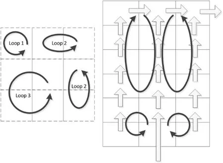
Fig.2.Types of recirculation loop in the flue gas zone.
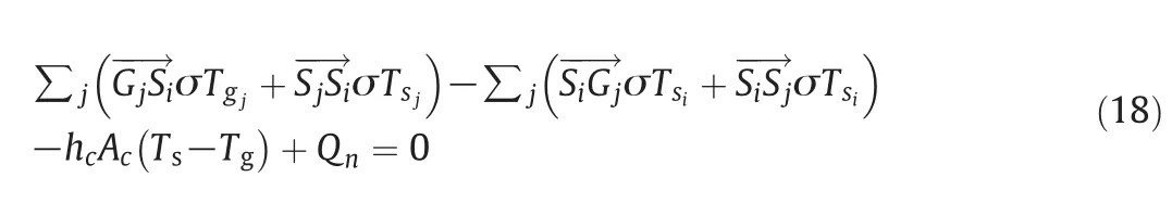
(2)For surface zones,Si,

whereQcis the convective energy that is transferred from/to the surface zone(s)to/from the neighboring volume zones,Qrthe total radiative energy that is retained in surfaceSifrom radiative transfer,andQnthe energy loss that flows out of the surface,which concludes the tube inside.
By substituting Eqs.(3)and(13)into Eq.(17),we have
3.Mathematical Model for the Tubular Reactor and Numerical Method
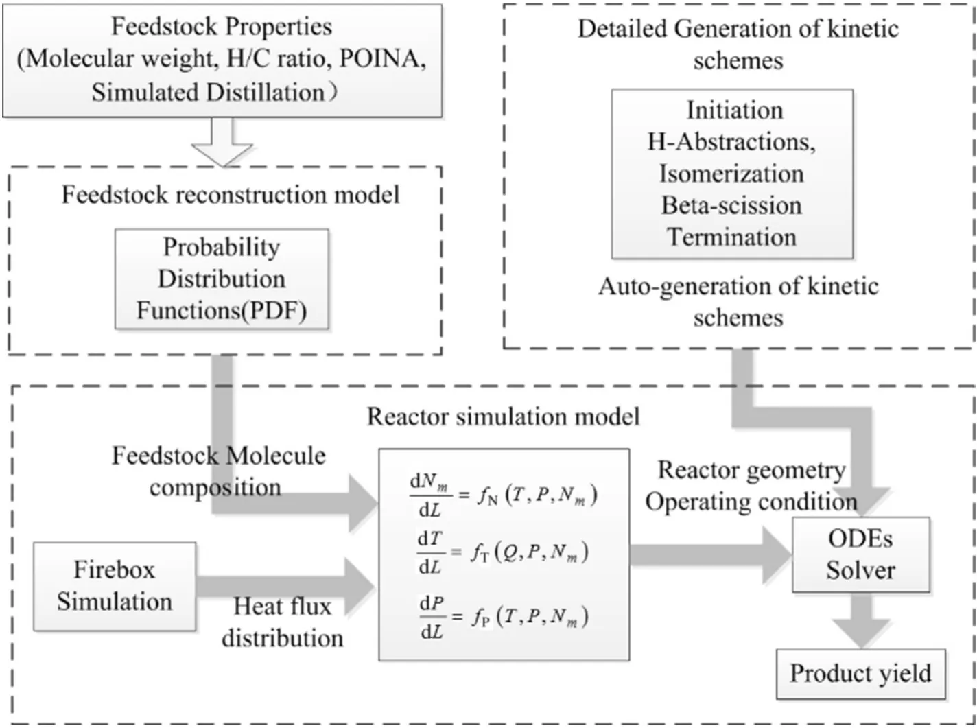
To establish the simulation model of the pyrolysis process coupling the firebox and the reactor,we combine the feedstock reconstruction model,a detailed kinetic scheme generator with both reaction networks and corresponding kinetic parameters,and the reactor simulation model[27].A flow chart of the whole simulation model is shown in Fig.3.
3.1.Feedstock reconstruction model
The feedstock reconstruction approach uses the probability distribution function[28]to modelthe composition ofthe complex oilfractions.The molecular composition of the petroleum fractions is calculated using Shannon entropy optimization with the bulk property ofthe feedstock such as average molecular weight,H/C ratio,density,true boiling point distillation curve,and PINA(paraffins,iso-paraffins,naphthenes,and aromatics)group number.
3.2.Detailed kinetic scheme generation
The radicalreaction mechanismplays the mostimportantrole in the thermal cracking of the hydrocarbon.For pyrolysis process,radical chain propagation mechanism can be classified as 5 types of reaction:Initiation,H-Abstraction,Isomerization,Beta-scission,and Termination reactions.Therefore,the reaction kinetic parameters used in this paper are referenced from literatures[29,30].As the manual generation of the whole set of reactions becomes intractable,especially when the hydrocarbon molecular weight is increased,an automatic generator of the reaction scheme is introduced in structuring the radical reaction networks with the estimated kinetic parameters.The elementary reaction model for steam cracking can be separated into two parts:light hydrocarbon reaction model and heavy hydrocarbon(carbon number greater than 5)reaction model.The light hydrocarbon reaction model is established using RMG software.The heavy hydrocarbon reaction model is generated using the radical mechanism.Finally,a kinetic scheme with 93 molecules,49 radicals and 4694 reactions is established for the full reaction model shown in Fig.4[21].
3.3.Reactor simulation model
Regarding the geometry of a tubular cracking furnace,a onedimensional reactor model is developed to simulate transfer and reaction processes.To solve the ordinary differential equations,we use Gear's methods;the heat fluxes(Qquantities)obtained from furnace simulations are substituted into these equations as well.This setofordinary differential equations is given by


4.Coupled System and an Industrial Application

Fig.4.Establishment steps for full reaction model.
To obtain product-yield data,the coupled modeloutlined in theflow chart(Fig.5)is executed.Some iterations between the firebox simulation and the reactor simulation are needed to obtain convergence to balance the interactive variables(tube skin temperature distribution and heat flux distribution).Thefirebox calculations enable the determination of the flow,combustion,and radiative heat transfer in the firebox.From the calculation of the heat flue flow field,the heat transfer input data for the reactor simulation are obtained by solving the energy balances(Eqs.(16)and(18))with the Levenberg–Marquardt method[31].For the reactor,the skin temperatures of the coils are obtained with cracking reactions in the coils considered as fixed boundary conditions for the firebox model.When the difference of tube skin temperature distribution between two iterations is less than margin of error,the model comes to the convergence.With these coupled iterations,product yield values are obtained which can be applied in the optimization of industrial operations.

Fig.5.Flow chart of coupled firebox/reactor simulation.
4.1.Industrial cracking furnace
If the coupled simulation converges,both firebox and reactor are in steady states.The temperature field,the flow field in the firebox,the heat flux distribution,and the temperature distribution in the tubular coil are all obtained and therefore a real-time operation simulation particularly for industrial purposes can be attained.The industrial cracking furnace that we studied is one type of industrial millisecond furnace,which has eight channels(Fig.6).In the full furnace,there are 48 floor burners arrayed into four rows on the floor and no side-wall burners;28×8 straight-line reaction tubes are arranged tightly in 8 channels.Details of the furnace dimensions and operating conditions are listed in Table 1 which are collected from real industrial process.
The tubular reactoris con figured as a system with a feedstock reconstruction model,detailed kinetic scheme generator,and the reactorsimulation model.The naphtha feedstock is reconstructed with details of the molecules given by their bulk properties(Table 1).These feedstock molecules are cracked into smaller molecules,the products of pyrolysis under the current operating conditions(Table 1).The geometrical dimensions of the straight-line tubular reactor are listed in Table 1.
4.2.Case results and discussion
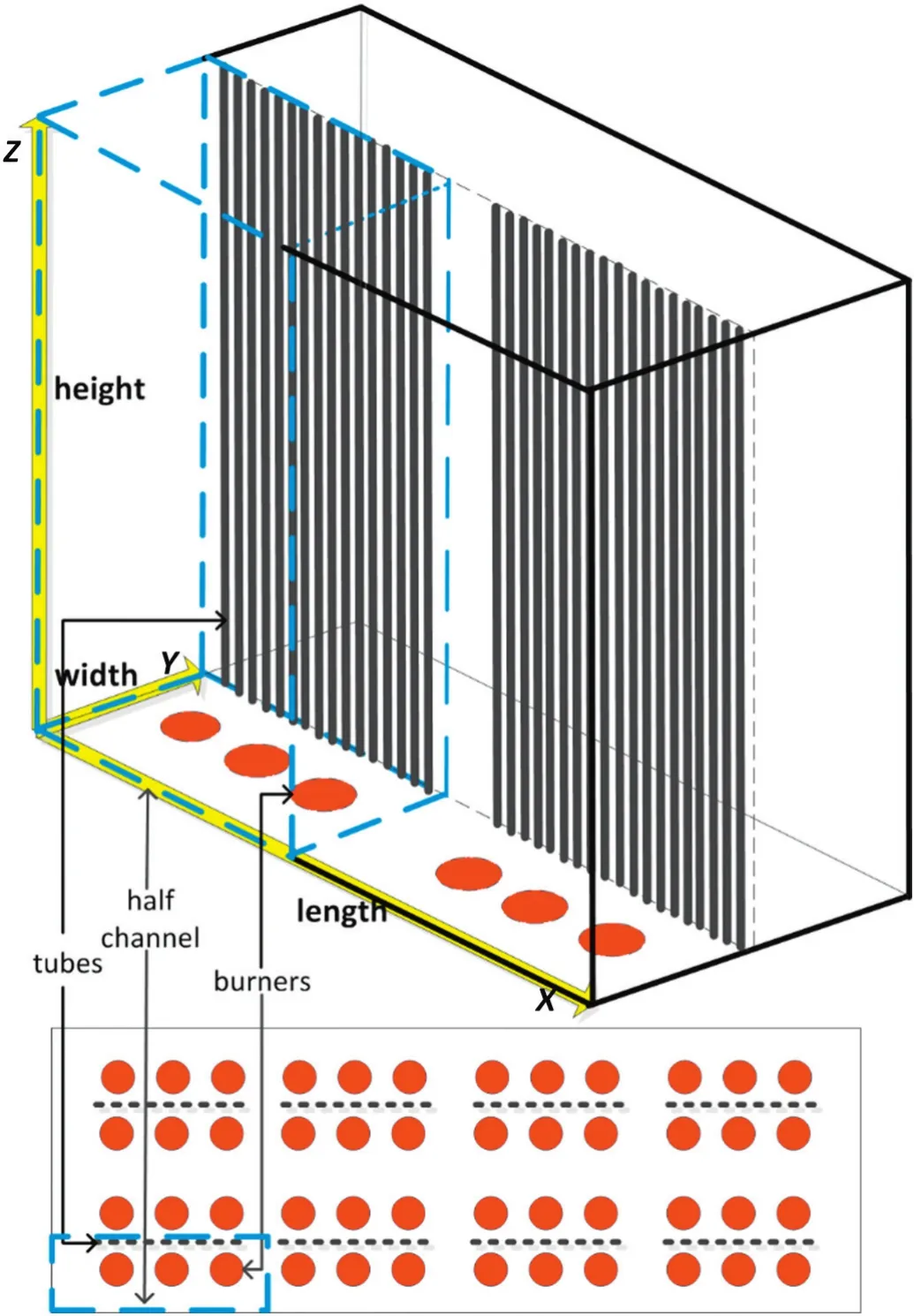
Fig.6.Schematic diagram of the cracking furnace.
The objective for using the coupled system is to predict product yields in the cracking process given the feedstock data and operating conditions such as the feedstock bulk properties,the furnace segment structure,fuel gas flow rate,and coil temperature.To obtain industrial operation simulations and optimizations,each part of the coupled system( firebox and reactor)needs to attain industry standards in computational accuracy.However,because of the demand for online operation simulations,the zone modelconstruction has to be simplified for speedy computations,one that balances accuracy and timeliness.Hence our furnace simulations focused on a simplified area in half one channel with three burners and has 36 zones including 6×3×1(height×width×length)volume zones and 18 corresponding surface zones for the firebox wall and the tube row surface.
For the recirculation model,theflow field is fixed along the direction between the volume zones and the regression process determines the flow rates for the recirculation loops,which are superimposed over the original flow field in the furnace(Fig.2).However,with high temperatures inside the cracking furnace and lack of measurement methods,industrial data for temperature and heat flux in the furnace are difficult to obtain.The quantities of recirculation loops are obtained by regression from the industrial measurement data.
With the regression method mentioned in Section 2.4,the industrial design data of the average heat flux pro file along the tube length,which is the design data corresponding to the furnace,is used as the objective function in the regression,because these data are closest to the reaction process of the tubular reactor design.The regression results are shown in Figs.7 and 8 in about 173 s of computation time using a 3.3-GHz CPU.The numberoftheflow in Fig.8 is flow field mixed by recirculation loops and the original flow field.
Fig.9 shows the simulation resultand industrialdata ofthe side-wall temperature distribution along the heightof the furnace.Here,the sidewall temperature first rises from 1295 K to its maximum value 1349 K,where the corresponding height is about 5.5 m,and then falls to 1310 K in about9 malong the furnace heightdirection.The industrialdata from an ethylene plant were measured by infrared thermometry and have a±15 K error range.The simulation results show good accordance with data over a broad range,especially the measured range.
In Fig.7,the peak in the heat flux is approximately the furnace height of 5 m.The simulated heat flux below the peak agrees roughly with industrial data.Above 5 m,the simulation result is below the design data curve.This error may arise from the flow field in the upper compartment of the furnace.Nevertheless,from the temperature field(second panel of Fig.10),we can see the temperature gradient between 7.9 m and 9.7 m is very small.The increase in the heat flux in the upper compartmentmustlead to an increase in temperature creating anotherpeak in temperature within the furnace.A double peak in temperature is unsuitable for furnace without side wall burners.
With the regression recirculation model,the gas temperature field in the furnace can be calculated and a comparison made between the recirculation zone model and the basic model in Fig.10.The gas temperature field is more uniform with recirculation,the highest temperature being strongly influenced by recirculation.Furthermore,the highest temperature with recirculation is about 1830 K whereas that for the basic model is about 2110 K.The regression recirculation model gives a more realistic gas temperature field.

Table 1Furnace dimensions(one channel),operating conditions and bulk properties of naphtha feedstock
To verify the recirculation model,three dimensional flow,combustion and radiation in the firebox of cracking furnace are simulated by CFD softwarefluent.Standardk-ε turbulence model, finite rate/eddy dissipation model,discrete ordinate model and weighted sum of graygas model are chosen to describe the processes in cracking furnace.With result of the CFD simulation influent software,the flow field is transformed into our recirculation loops.In Fig.10,the temperaturefield of the recirculation model estimated by the CFD flow field and the temperature field from Fluent are shown as well(third and fourth panels).The similarity of these two fields represents the recirculation model estimated by the CFD is correct in the furnace simulation.
Finally,the reactor model can be coupled into the system to give accurate heat flux distributions;productyields obtained by the tubular reactor model are listed in Table 2.The regression model shows strong agreement with industrial data.The result of the recirculation with CFD is similar with the regression and better than the basic model.According to our analysis,results of the recirculation model provide uniform heat flux and temperature distribution are a fit better to the industrial data.In Fig.11,the temperatures for the tubular reactor core and outside wall show a similar trend as that given by the regression circulation zone model,the reason being a higher accuracy in predicting product yields.The situation means the designed heat flux for the tubular reactor is the core of the coupled system.The heat flux distribution influences the reactions most and the best designed furnaces need to have reaction temperatures within the tubular reactor within design specifications.However,there is an inevitable deviation with respect to the industrial operational process.In Fig.7,the tail of the simulation curve is lower for the designed curve which reduces the difference between the reaction temperature and tubular wall temperature(Fig.11).Fortunately,the result for recirculation zone is suf ficiently accurate for industrial demand.
The computation time for the model needs to be concerned most in this paper.With the same CPU,the zone method expends only 5 s whereas the CFD method influent needs almost seven days because of differences in the number of partitions.Computation times for industrial naphtha cracking furnaces are crucial for fast real-time operating optimizations.The advantage of our model is obvious.No matter what kind of data is applied to estimate the circulation loops,the accuracy of the prediction is depending on the accuracy of the data you can have.When you obtain the accurate industrial measure data such as the heat flux pro files in our work,the recirculation model can estimate the flow field more accurately.In this way,the recirculation model shows its advantages not only in calculating time but also the accuracy.In addition,the CFD simulation result can help to verify the result the data regression if the CFD model can be accessible.
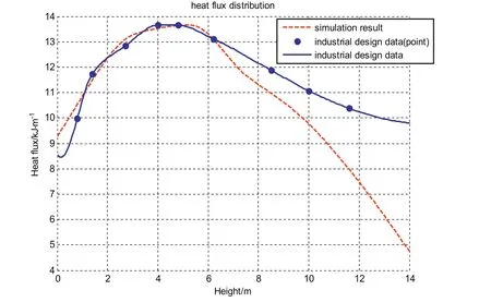
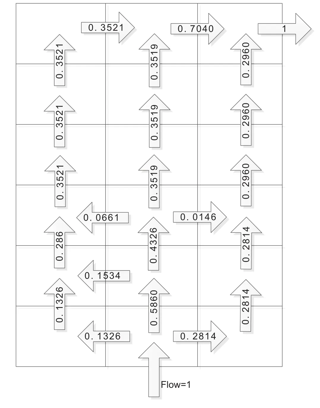
Fig.8.Recirculation-loop field along the furnace height and length.
5.Conclusions
A coupled simulation system including both the firebox and the reactor is established to simulate the naphtha pyrolysis tubular-furnace.The two-dimensional data-based recirculation zonal model is well invented in flow field estimation which decreases the calculating scale of firebox.The flow field is estimated with industrial data.The temperature field obtained using the recirculation zone method is more uniform than that obtained by the basic flow field model and the results of the recirculation zone method show good agreement with industrial data.In particular,the tube wall temperature distribution of reactor using the zone method shows good trends with reaction temperature,and productyields are very accurate satisfying the industrialapplication requirements.In addition,a CFD simulation is constructed to verify the recirculation model and temperature field with this flow field shows similar with thefluent software.The calculating time of the recirculation modelcan wellsatisfy the industrialsimulation.In general,the coupled simulations using the recirculation model give both precise prediction and less computation time which are fundamental in achieving real-time simulation of industrial naphtha-cracking furnace operations.
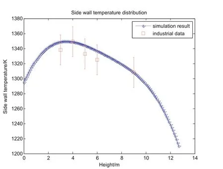
Fig.9.Comparison between the simulation result and industrial data of the side-wall temperature distribution along the furnace height.

Fig.10.Flue gas temperature fields with furnace height and width.

Fig.11.Temperature distribution along the length of tubular reactor.
Nomenclature
Acthe area of the convective heat,m2
aε,ithe emissivity weighting factor for theith fictitious gray gas,the bracketed quantity is theith fictitious gray gas emissivity
Cpmthe heat capacity at constant pressure,J·K-1
Dithe inner diameter of reaction tube,m
Dothe outer diameter of reaction tube,m
fthe frictional factor
fcthe total fuel consumption ratio
Gthe mass flow rate of the gas in reaction tube,kg·s-1

hthe flue gas height in the furnace,m
hcthe convective heat transfer coefficient,W·(K·m2)-1
kthe absorption coefficient of the gray gas,m-1
kwthe total heat transfer coefficient,W·(K·m2)-1
Lthe length of the reaction tube,m
Lfthe flame height in the furnace,m
lsthe path length,m
mithe mass flux of componentsiof the fuel,kg·s-1
Nmthe concentration of substancemin reaction tube
Prthe pressure in reaction tube,Pa
pthe sum of the partial pressures of all absorbing gases
Qbthe combustion heat,W
Qcthe convection heat transfer,W
Qfheat transfer by the furnaces,W·m-1
Qnthe energy loss that flows out of the system,W
QRSiSjthe heat flux from reflection
Qrthe total radiative energy,W
qithe heat of combustion of the componentsiof the fuel,W
rithe reaction rate of reactioni
rijthe size of the vector that connects the center of the two elements to each other,m
Sthe flow area of reaction tube,m2

SiRSjthe reflective heat flux rate
Tgthe flue gas temperature of the volume zone,K
Tsthe temperature of the surface zone,K
TSithe temperature of the surface zoneSi,K
Trthe temperature in the reaction tube,K
Vthe volume flow rate of the gas in reaction tube,m3·s-1
vimthe stoichiometric coefficient of substancemin reactioni
Wgthe equivalent length of reaction tube,m
ΔHthe net enthalpy,J·(kg·K)-1
ΔH0fmthe standard enthalpy of formation of substancem,J·(kg·K)-1
Δhthe height of the vertical interval,m
εsjthe surface absorptivity(the surface blackness)
θi,θjthe angle between the normal vector of surface elements and the above-mentioned vector
κithe absorption coefficient of theith gray gas
ρrthe density of the gas in reaction tube,kg·m-3
ρsjthe surface reflectivity
[1]G.J.Heynderickx,A.J.Oprins,G.B.Marin,E.Dick,Three-dimensional flow patterns in cracking furnaces with long- flame burners,AIChE J.47(2001)388–400.
[2]T.Detemmerman,G.Froment,Three dimensional coupled simulation of furnaces and reactor tubes for the thermal cracking of hydrocarbons,Oil Gas Sci.Technol.53(1998)181–194.
[3]G.Hu,H.Wang,F.Qian,K.M.Van Geem,C.M.Schietekat,G.B.Marin,Coupled simulation of an industrial naphtha cracking furnace equipped with long- flame and radiation burners,Comput.Chem.Eng.38(2012)24–34.
[4]X.Lan,J.Gao,C.Xu,H.Zhang,Numericalsimulation of transfer and reaction processes in ethylene furnaces,Chem.Eng.Res.Des.85(2007)1565–1579.
[5]A.Niaei,J.Tow fighi,S.M.Sadrameli,R.Karimzadeh,The combined simulation of heat transfer and pyrolysis reactions in industrial cracking furnaces,Appl.Therm.Eng.24(2004)2251–2265.
[6]G.D.Stefanidis,K.M.Van Geem,G.J.Heynderickx,G.B.Marin,Evaluation of highemissivity coatings in steam cracking furnaces using a non-grey gas radiation model,Chem.Eng.J.137(2008)411–421.
[7]G.Stefanidis,B.Merci,G.J.Heynderickx,G.B.Marin,CFD simulations of steam cracking furnaces using detailed combustion mechanisms,Comput.Chem.Eng.30(2006)635–649.
[8]A.Habibi,B.Merci,G.J.Heynderickx,Impact of radiation models in CFD simulations of steam cracking furnaces,Comput.Chem.Eng.31(2007)1389–1406.
[9]H.Guihua,W.Honggang,Q.Feng,Numerical simulation on flow,combustion and heat transfer of ethylene cracking furnaces,Chem.Eng.Sci.66(2011)1600–1611.
[10]P.J.Stopford,Recent applications of CFD modelling in the power generation and combustion industries,Appl.Math.Model.26(2002)351–374.
[11]A.Batu,N.Selcuk,Modeling of radiative heat transfer in the freeboard of a fluidized bed combustor using the zone method of analysis,Turk.J.Eng.Environ.Sci.26(2001)49–58.
[12]H.Hottel,E.Cohen,Radiant heat exchange in a gas- filled enclosure:allowance for nonuniformity of gas temperature,AIChE J.4(1958)3–14.
[13]H.B.Becker,A mathematicalsolution for gas-to-surface radiative exchange area for a rectangular parallelepiped enclosure containing a gray medium,J.HeatTransf.-Trans.ASME99(1977)203–207.
[14]R.J.Tucker,Direct exchange areas for calculating radiation transfer in rectangular furnaces,J.Heat Transf.-Trans.ASME108(1986)707–710.
[15]H.Erkku,Radiant Heat Exchange in Gas- filled Slabs and Cylinders,PhD Thesis,Massachusetts Institute of Technology,USA,1959.
[16]H.Ebrahimi,A.Zamaniyan,J.S.Soltan Mohammadzadeh,A.A.Khalili,Zonal modeling of radiative heat transfer in industrial furnaces using simplified model for exchange area calculation,Appl.Math.Model.37(2013)8004–8015.
[17]M.F.Modest,Radiative Heat Transfer,Academic Press,2013.
[18]W.R.Shu,L.L.Ross,Cracking severity index in pyrolysis of petroleum fractions,Ind.Eng.Chem.Process.Des.Dev.21(1982)371–377.
[19]P.Kumar,D.Kunzru,Modeling ofnaphtha pyrolysis,Ind.Eng.Chem.Process.Des.Dev.24(1985)774–782.
[20]M.Dente,E.Ranzi,A.Goossens,Detailed prediction of olefin yields from hydrocarbon pyrolysis through a fundamental simulation model(SPYRO),Comput.Chem.Eng.3(1979)61–75.
[21]Z.Fang,T.Qiu,B.Chen,Improvement of ethylene cracking reaction network with network flow analysis algorithm,Comput.Chem.Eng.91(2016)182–194.
[22]W.Zhou,T.Qiu,Zone modeling of radiative heat transfer in industrial furnaces using adjusted Monte-Carlo integral method for direct exchange area calculation,Appl.Therm.Eng.81(2015)161–167.
[23]H.C.Hottel,A.F.Saro fim,Radiative Transfer,McGraw-Hill,1967.
[24]N.Selçuk,R.G.Siddall,J.M.Beér,A comparison of mathematical models of the radiative behaviour of an industrial heater,Chem.Eng.Sci.30(1975)871–876.
[25]J.S.Truelove,A Mixed Grey Gas Model for Flame Radiation,Thermodynamics Division,AERE,1976.
[26]T.F.Smith,Z.F.Shen,J.N.Friedman,Evaluation of coefficients for the weighted sum of gray gases model,Trans.ASME J.Heat Transf.104(1982)602–608.
[27]J.J.Noble,The zone method:explicit matrix relations for total exchange areas,Int.J.Heat Mass Transf.18(1975)261–269.
[28]S.P.Pyl,Z.Hou,K.M.Van Geem,M.-F.Reyniers,G.B.Marin,M.T.Klein,Modeling the composition of crude oil fractions using constrained homologous series,Ind.Eng.Chem.Res.50(2011)10850–10858.
[29]M.Dente,G.Bozzano,T.Faravelli,A.Marongiu,S.Pierucci,E.Ranzi,Kinetic modelling of pyrolysis processes in gas and condensed phase,Adv.Chem.Eng.32(2007)51–166.
[30]E.Ranzi,A.Frassoldati,S.Granata,T.Faravelli,Wide-range kinetic modeling study of the pyrolysis,partial oxidation,and combustion of heavyn-alkanes,Ind.Eng.Chem.Res.44(2005)5170–5183.
[31]J.Pujol,The solution of nonlinear inverse problems and the Levenberg–Marquardt method,Geophysics72(2007)W1–W16.
 Chinese Journal of Chemical Engineering2017年8期
- Chinese Journal of Chemical Engineering的其它文章
- Optimal design of heat exchanger header for coal gasification in supercritical water through CFD simulations☆
- Integration strategies of hydrogen network in a refinery based on operational optimization of hydrotreating units☆
- Application of the dividing wall column to olefin separation influidization methanol to propylene(FMTP)process☆
- Optimization and control of a reactive distillation process for the synthesis of dimethyl carbonate☆
- A systematic strategy for multi-period heat exchanger network retro fit under multiple practical restrictions☆
- Performance of CO2 absorption in a diameter-varying spray tower☆