
A crossed focused vortex beam with application to cold molecules*
2021-11-23 07:26MengXia夏梦YalingYin尹亚玲ChunyingPei裴春莹YuerYe叶玉儿RuoxiGu顾若溪KangYan严康DiWu吴迪YongXia夏勇andJianpingYin印建平
Chinese Physics B 2021年11期
Meng Xia(夏梦) Yaling Yin(尹亚玲) Chunying Pei(裴春莹) Yuer Ye(叶玉儿) Ruoxi Gu(顾若溪)Kang Yan(严康) Di Wu(吴迪) Yong Xia(夏勇) and Jianping Yin(印建平)
1State Key Laboratory of Precision Apectroscopy,School of Physics and Electronic Science,East China Normal University,Shanghai 200241,China
2Collaborative Innovation Center of Extreme Optics,Shanxi University,Taiyuan 030006,China
3NYU-ECNU Institute of Physics at NYU Shanghai,Shanghai 200062,China
Keywords: cold molecule,crossed focused vortex beam,propagation characteristics,optical potential
1. Introduction
Recent advances in laser cooling and quantum state control of diatomic molecules propose a powerful platform for precision measurement, ultracold chemistry and quantum information science.[1,2]Tremendous progress has been made in the magneto-optical trap (MOT) of diatomic molecules, i.e.,SrF,[3]CaF,[4,5]and YO.[6,7]To date,the reported temperature of the cooled diatomic molecule is well below the Doppler limit.[4,8-10]In 2017, Anderegget al. reported that the maximum number of molecules,1.0×105,were captured through radio frequency MOT on CaF molecules.[5]Most applications of ultracold molecules require quantum state control, so the molecules in a MOT were first loaded into a conservative trap,e.g., optical dipole traps,[11]magnetic traps,[12,13]and optical tweezer arrays.[14]In 2018, Anderegget al. loaded the sub-Doppler cooled CaF molecules into a far-detuned optical dipole trap, and the trapped samples lasted for a lifetime of 750 ms at a temperature of 60 µK. The achieved densities were 8×107cm−3and in particular the phase-space densities were 2×10⁻⁹, that is, 35 times higher than that from the sub-Doppler-cooled samples in free space.[11]Williamset al.achieved magnetic trapping of laser-cooled CaF molecules in a single quantum state, and about 5×10³molecules were trapped with a density of 1.2×105cm−3for a lifetime of 2 s at a temperature of 70 µK[12]McCarronet al.employed an efficient transfer of ultracold SrF molecules from a radio frequency MOT into a magnetic quadrupole trap: 600-800 molecules in a single quantum state were trapped with a density of 3×104cm−3for a lifetime of 1 s at a temperature of 260µK.[13]In 2019, Anderegget al.also reported an optical tweezer array of single ultracold CaF molecules with high-fidelity detection, opening the door for studying the intermolecular collisions and state-selective ultracold quantum chemistry.[14]
The optical dipole trap is based on the interaction of light with the induced electric dipole moment of the trapped atoms and molecules,so it is applicable to the accurate,non-contact manipulation and control of cold samples.[15,16]The far-offresonance optical dipole traps (FORT), composed of one or two intense and continuous-wave laser beams,are used to confine an ultracold sample. In 1995,the first type of red-detuned FORT composed of two crossed focused YAG laser beams was applied to study the evaporative cooling of Na atoms.[17]Such a FORT has a wide range of applications in areas of high precision imaging of the optical clock,high-density trapping of cold samples, and all-optical atomic Bose-Einstein condensate.[18-20]One can also generate a blue-detuned,hollow FORT, which has some unique physical properties: (i)the mean photon scattering rate is lower,and the trap lifetime of atoms is longer; (ii) the well depth is deeper; (iii) there exists an intensity-gradient induced Sisyphus cooling.[16]In 1997, Kugaet al. demonstrated a Laguerre-Gaussian-beam trap for cold85Rb atoms with a blue-detuned frequency of~60 GHz. The atoms loaded from a MOT were trapped in the dark core (a cylinder box with 1.5 mm in diameter and 2 mm in height) in the transverse direction with the help of two additional,blue-detuned plug beams to confine the atomic motion along the optical axis.[21]Afterwards,several different hollow FORTs were proposed and demonstrated.[22-26]For example,the other crossed hollow beam is generated by overlapping two co-propagating, Laguerre-Gaussian (LG01) beams with orthogonal polarization. The LG01beam is then split into two co-propagating beams separated by several mm propagating through a calcite beam displacer. Using a high numerical aperture lens,the beams are tightly focused and overlapped at the center of the vacuum cell. A crossed vortex bottle beam is formed with the width of 5.5µm in the radial direction and a longitudinal length of 52µm.[24,25]However,the current hollow FORTs have two main disadvantages. Firstly, there is a large difference regarding the optical potential well between the radial and the axial directions. The well’s structure is either ellipsoidal or cylindrical tube,which causes an imperfect intensity distribution,a large trapping volume and a small intensity gradient. Secondly,the trapping volume cannot be dynamically tunable.
Here, we propose a scheme to construct an optical potential wells by the crossed, focused, vortex beam (CFVB).Such beam has a near-zero intensity distribution in the center with a high-intensity light outwards, which provides a repulsive potential upon being blue-detuned from resonance, so as to permit molecules being trapped in the central region. Comparing with the previous studies, the CFVB here has a much smaller trapping volume,and is tunable by changing the quantum number of the orbital angular momentum (OAM). This report consists of five sections. In Section 1, it is the introduction as already described. In Section 2, it describes the experimental scheme. In Section 3,it describes the generation and propagation characteristics of the vortex beams which are divided into two parts. In the first part,it describes the generation and intensity distributions of the single,focused,vortex beam (SFVB) in free space, and the relationship of the dark spot size (DSS) with the incident Gaussian beam’s waistw0,and the lens’focal lengthf.In the second part,it describes the generation and intensity distribution of the CFVB,and in particular the relationship of the DSS with the OAM’s quantum numberl. In Section 4,it describes the potential applications of the CFVB in trapping and cooling of MgF molecules. In Section 5,it summaries the main results and conclusions.
2. Experimental scheme
Figure 1 shows the experimental setup for the generation of a CFVB.The Gaussian laser beam from a He-Ne laser first passes through a linear polarizer and then an optical isolator,and then through a collimating and expanding beam system consisting of a spatial filter and lens L1(f1=400 mm). The used spatial filter consists of microscope objectives(10 times)and an aperture(50µm)to remove any higher-order diffracted terms. Next, the beam passes through a beam splitter, and is divided into two beams with equal power. Two linear polarizers are used to satisfy the polarization requirement of the SLM1and SLM2. The SLM1(Holoeye) has a resolution of 1024×768 pixels and 19 µm of pixel pitch, and the SLM2(Holoeye)has a resolution of 1920×1080 pixels and 8.0µm of pixel pitch. The two laser beams are then modulated by the hybrid holograms imprinted on the SLM; that is to say, each beam passes through an azimuthally distributed 2π-phase and is focused by a thin lens phase with a focal lengthf, and a SFVB will be produced behind the BS owing to the completely destructive interference effect at the beam center. When two SFVBs are crossed at both focal planes,a tightly focused dark spot with a small trapping volume is formed(see the right inset in Fig. 1). In this scheme, two SLMs function as the diffractive optical elements to control both the phase and the polarization for the incident light. Through the SLM software, we can switch the binary bitmap as the phase pattern (for example,OAM quantum numberl=1)shown on the SLM screen,which is shown in the left inset of Fig.1.
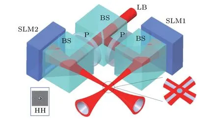
Fig.1. Experimental setup for generation of crossed,focused,vortex beams.Acronyms are:LB for laser beam,P for linear polarizer,BS for beam splitter,SLM for spatial light modulator. The inset gray pattern is the hybrid hologram(HH)by a combination of a vortex phase with OAM quantum number l=1 and a lens phase.
The phase patternφtotalused to drive the SLM includes two contributions and readsφtotal=φvortex+φlens.φvortexis the vortex phase, andφlensis the phase pattern acting as a lens,which allows us to fine-tune the focusing of the vortex beam.The hybrid holograms and corresponding phase profiles are shown in Fig.2. For the OAM,the quantum numberlis 2,5,10,and 20,respectively.

Fig.2. Hybrid holograms(upper panel)and phase profiles(lower panel)for the generated vortex beams with the OAM’s l=2,5,10,20.
3. Generation and propagation characteristics of vortex beam in free space
3.1. Single focused vortex beam
A common vortex beam has a complex amplitude with the phase,expressed as exp(ilϕ),whereϕis the azimuthal angle,andlis also called the topological charge of an OAM beam.In our scheme,forl=1,the vortex phase hologram imprinted on the SLM is equivalent to a traditional,azimuthally distributed 2πphase plate.[27]Besides, a lens phase can be shown onto the SLM.We calibrate the focal lengthfof the lens phase on the SLM,and plot a quantitative curve for the lens phase with the focal lengthf. The focal lengthfis inversely proportional to the lens phase value.
The detailed mechanism of generating the SFVB is described as follows. The phase factor of exp(ilϕ)corresponds to a phase singularity at the beam center of which the intensity is zero-due to the destructive interference. By takingl=1,the continuous azimuthal phase retardation of the vortex phase increases from 0 to 2πwhile increases the SLM’s gray level.The phase difference between the two sides of an arbitrary straight line passing through the circular center of the hologram is always equal toπ,and the center of the hologram is a symmetric center of thisπphase deference and is azimuthally distributed.These will lead to a completely destructive interference effect at the center of the incident Gaussian laser beam. Therefore,the axial intensity of the output beam will be reduced to zero,and the generated beam is a vortex beam with an OAM order ofl=1. At the same time,when a lens phase is encoded onto the SLM,the laser beam is reflected by the hybrid hologram,so a focused vortex beam is formed.
When a collimated Gaussian laser beam is incident on the hybrid hologram, the field distribution of the diffraction field- reflected by the SLM in a polar coordinate - can be obtained according to the Fresnel diffraction integration[27]
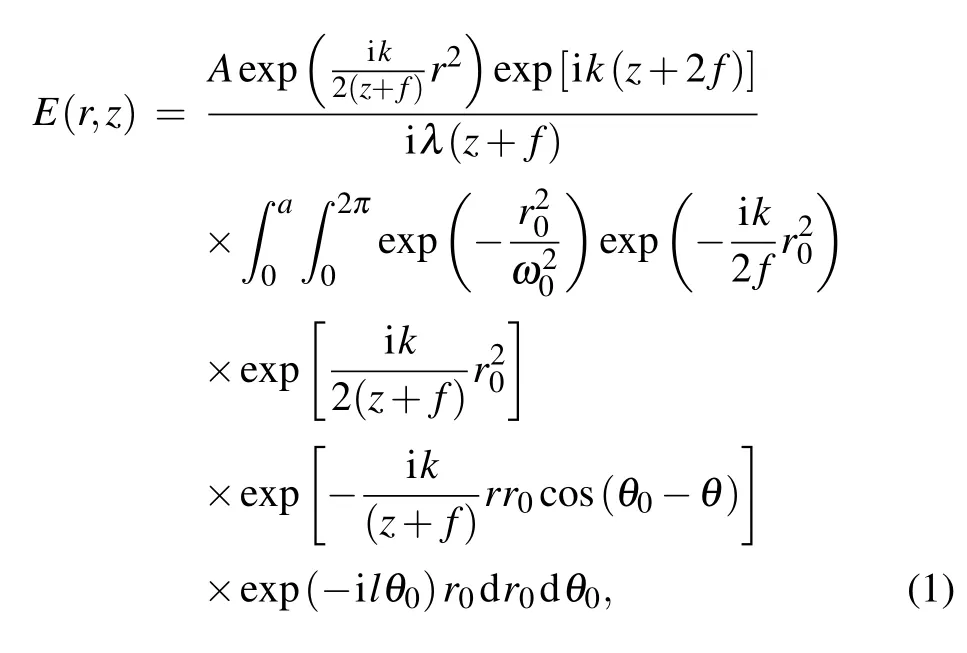
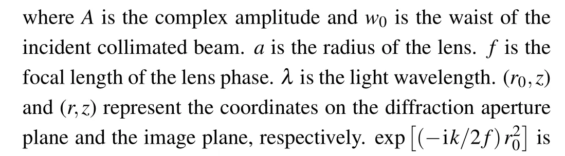
Fig.3. (a)-(c)Normalized radial 1D intensity profiles and 2D intensity distributions of the SFVB at the propagation distance z=−150, 0, 150 mm,respectively. The experimental parameters are w0 =1.2 mm, f =250 mm.(d)Relationship of the DSS of the SFVB with the propagation distance z for w0=1.2 mm and f =250 mm.The line represents the theoretical curve,and the squares correspond to the experimental data.
The intensity distribution of the SFVB in free space can be given by

Based on Eqs.(1)and(2),we study the propagating properties of the SFVB in free space. We define the special parameter,the dark spot size,i.e.,DSS,as the full width at the half maximum (FWHM) of the radial-intensity distribution inside the notch of the SFVB.[28]In our experiments,forl=1,the intensity profiles of the SFVB,with the beam propagation direction atz=−150, 0 and 150 mm away from the focal plane, are measured and shown in Figs.3(a)-3(c),respectively. As seen from Figs.3(a)-3(c),owing to the completely(r=0)and partially(r ̸=0)destructive interference effects around the central region of the vortex beam, a SFVB with a Gaussian intensity profile will be generated. But with the increase of the radial positionr, the function of the 2πphase for the focused laser beam shows periodic partially destructive and constructive interference effects, which results in a periodic oscillated modulation on the Gaussian intensity profile except for the focal plane ofz=0.
The relationship of the DSS with the propagation distancezis seen in Fig.3(d).The line represents the calculated results,and the squares represent the experimental results. The waist of the incident beam isw0=1.2 mm, and the focal length of the lens isf=250 mm. There is an impressive feature of this propagation characteristic. Before the focal plane, the DSS gradually increases up to the maximum value(202.4µm)at the position ofz=−f/2 (half focal length), and then decreases to the minimum value (38.3 µm) at the focal point.After the focal plane,the focused vortex beam propagates with a constant divergent angle. In fact, the measured DSS values agree well with the modeling.
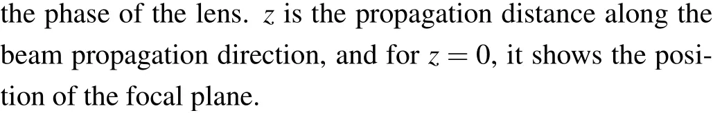
We then investigate the relationship of the DSS in the focal plane ofz=0 with the focal lengthfand the waistw0.The experimental (dots) and theoretical (lines) results are shown in Figs. 4(a) and 4(b), which agree with each other. From Fig. 4(a), it is clear that the DSS increases linearly with an increase of the focal lengthf. From Fig. 4(b), with an increase of the waistw0, the DSS decreases exponentially instead. Therefore, with a shorter focal lengthfand a larger waistw0,an extremely small DSS for the vortex beam can be obtained.
To measure the OAM of the SFVB,a straightforward interferometric method can be used. The principle is that due to the incomplete phase modulation of the SLM,the reflected beam contains the unmodulated portion of an incident Gaussian beam,which will interfere with the focused vortex beam to generate the petal patterns.The number of petals is in agreement with the value of the OAM that the modulated beam carries.[29]
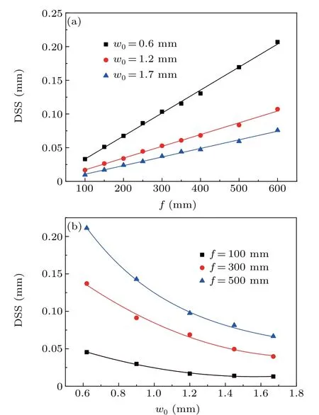
Fig. 4. (a) Relationship of the DSS at the focal point with the focal length f for w0 =0.6, 1.2 and 1.7 mm. (b) Relationship of the DSS at the focal point with the waist w0 for f =100,300 and 500 mm. The square,circle and triangle are experimental data. The solid lines are theoretical ones.
3.2. Crossed focused vortex beam
The SFVB above is a kind of 2D hollow beam,which can only be implemented for guiding and focusing of molecules.A 3D dark hollow region can be formed by the orthogonal superposition of a pair of SFVBs in the focal planes, i.e.,CFVB, which is in fact capable of cooling and trapping cold molecules. Two superimposed SFVBs do not interfere with each other due to the different polarizations, and the output mode can be expressed as a superposition of Mach-Zehnder type optical components.[30]
In the experiment,a CCD with 45°relative to the horizontal direction was in place to detect the intensity distributions of the CFVB.Figure 5(a)gives a schematic diagram of the detection region at five positionsz1-z5. Thez1andz5planes are far away from the superposition region of the two SFVBs, while thez2andz4planes involve the partial superposition region.Thez3plane shows a full superposition in the focal planes of the two SFVBs. Figures 5(b)-5(f)show 1D(black lines)and 2D (color insets) intensity distributions for these five planes,respectively. For the case ofz1(orz5) plane in Fig. 5(b) (or Fig. 5(f)), we detect the light intensity distribution on cross section of two SFVBs. Their 2D images show two hollow circles with the same size. When the detecting plane starts to be closer to the center of the superposed region, the two hollow circles cross, which are seen in Figs.5(c)and 5(e). At thez3plane, two hollow circles superpose completely and thus become a single closed hollow circle, as seen in Fig. 5(d). So,the 3D enclosed and focused hollow trap is eventually formed.
Importantly, we study the dependence of the DSS of the CFVB on the OAM’s quantum numberlat the focal point at differentfandw0. It can be seen from Fig.6(a)that for fixedw0=1.2 mm,the DSS of the CFVB at thez3plane is linearly proportional to the OAM’s quantum numberl. Also, smallerf,smaller DSS.Atf=150 mm,whenldecreases from 16 to 1,the DSS decreases accordingly,from 310.7µm to 23.5µm,and the corresponding trapping volume of the CFVB is compressed by a factor of up to 2.3×10³times. From Fig. 6(b),for fixedf=150 mm, the DSS of the CFVB at thez3plane is also linearly proportional to the OAM’s quantum numberl. But, biggerw0,smaller DSS.Atw0=1.7 mm, whenldecreases from 16 to 1, the DSS decreases accordingly, from 388.7 µm to 16.3 µm, and the corresponding trapping volume of the CFVB is compressed by a factor of up to 1.3×10⁴times.
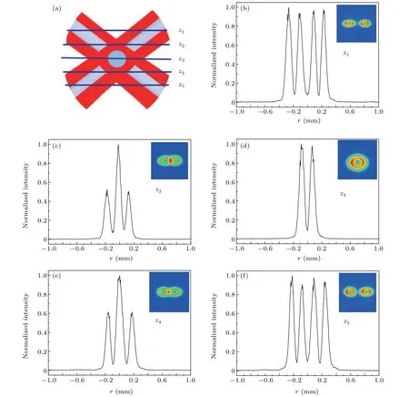
Fig.5. (a)Schematic diagram of the CCD detection near the center of the superposed region of the CFVB.z1,z2,z3,z4,and z5 represent the locations of the detection plane. (b)-(f)The 1D(black)and 2D(color)optical intensity distributions at different planes for l=1,w0=1.2 mm,and f =250 mm.
Fig. 6. (a) Relationship of the DSS of the CFVB at the z3 plane with l at different f for fixed w0=1.2 mm. (b)Relationship of the DSS of the CFVB at the z3 plane with l at different w0 for fixed f =150 mm. The scatter plots represent the experimental data,and the solid lines represent the fitted curves.
The above results clearly show that with a shorter focal lengthfand a larger waistw0, a desired CFVB with an extremely small DSS can be obtained. The DSS can also be dynamically tuned by the OAM’s quantum number to further increase the density of trapped molecules.
If we compress the trapped volume,the temperature of the trapped molecule will go up because of the heating effect. For example, in Ref. [12], they demonstrate the efficient transfer of SrF molecules from a magneto-optical trap into a conservative magnetic quadrupole trap. Their scheme begins with a blue-detuned optical molasses to cool the SrF molecules to 50 µK. The gradient of the trapping magnetic field increases by 4 times during compression,so the temperature of trapped molecule is increased to 260µK.
4. Applications to cooling and trapping of MgF molecules
When the MgF molecule, upon electronic excitation of X2Σ+to A2Π states, moves in an inhomogeneous light field,it experiences an optical dipole force,which can be described by the AC Stark shifts of the hyperfine energy levels in the2Σ state for the Hunds case (b) to them in the A2Π state for the Hunds case(a).[11,31]The effect of the multilevel structure of molecules on their response to an electromagnetic field may be conveniently described with the help of the electric dipole polarizability.
The AC Stark shift of a specific state|ϕκ〉in X2Σ+thus can be given by[31]
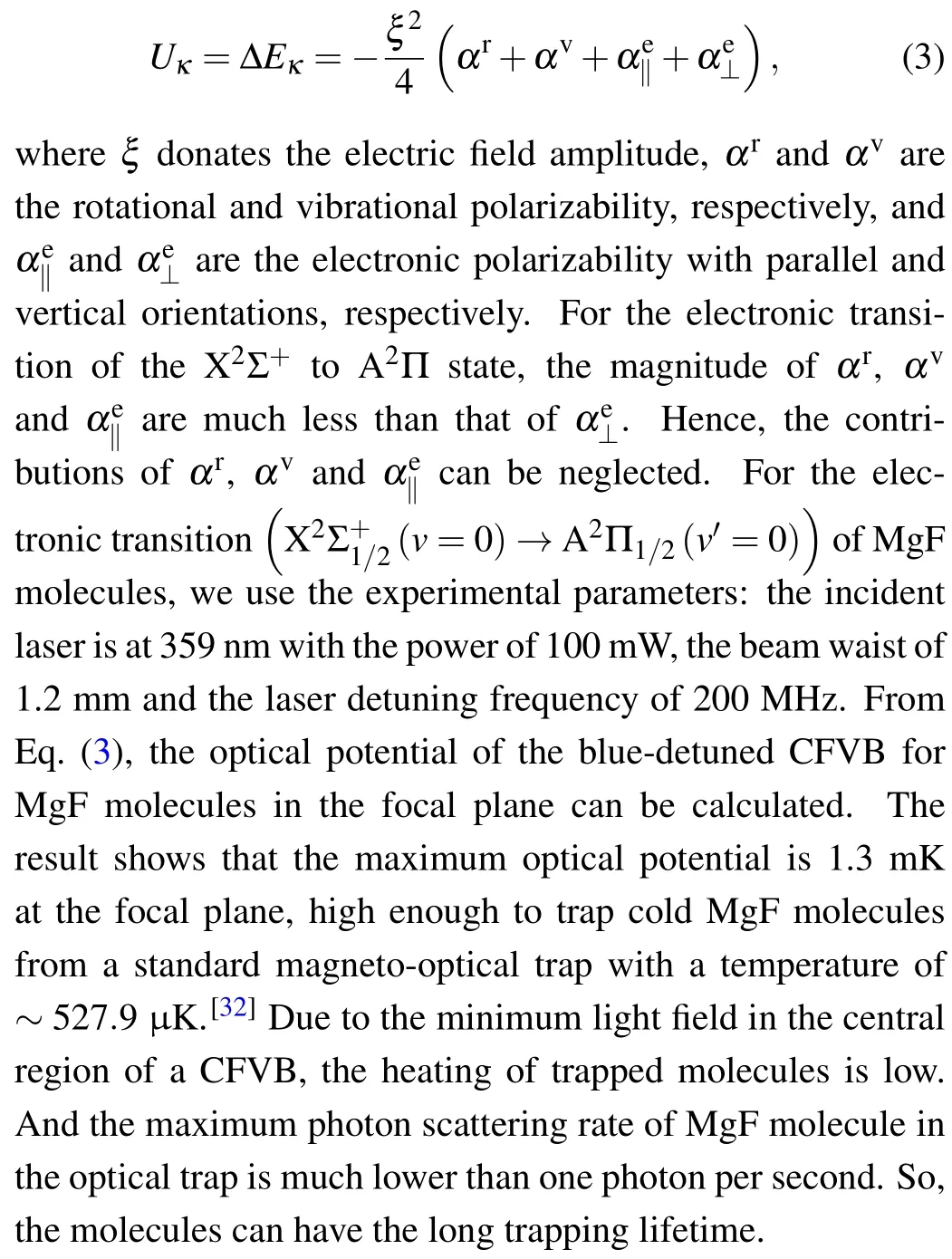
We can also prepare the ultracold MgF molecules from a slowed molecular beam by using the intensity-gradient induced Sisyphus cooling.[31,33]The cooling is based on a bluedetuned CFVB and a weak repumping laser beam. Because of the strong intensity-gradient force and the low-rate spontaneous emission,the molecules in the CFVB trap can be cooled to the lower temperature of several photon recoils.
5. Conclusion
In conclusion, we generate a dynamically adjustable,crossed, focused, vortex beam by imprinting a pair of hybrid holograms with the vortex phase and the lens phase onto a SLM.We study the propagation characteristics of such vortex beam in free space. Our study shows that at the focal point,with a shorter focal length and a larger incident Gaussian beam’s waist, an extremely small DSS at the 3D dark hollow region of the crossed, focused, vortex beam can be obtained,which is 16.3µm. Forf=150 mm andw0=1.7 mm,when the OAM’s quantum numberldecreases from 16 to 1,the DSS decreases accordingly,from 388.7µm to 16.3µm,and the corresponding trapping volume of the CFVB can be compressed by a factor of up to 1.3×10⁴times. Looking forward to the future applications, when cold molecules are loaded from a standard magneto-optical trap, they can be trapped in a 3D dark hollow region, and then cooled by intensity-gradient induced Sisyphus cooling. Thus, even an all-optically cooled and trapped Bose-Einstein condensate in the crossed,focused,vortex beam is feasible.[16]
猜你喜欢
安徽农业科学(2022年9期)2022-05-17
电影文学(2020年12期)2020-11-14
传奇故事(破茧成蝶)(2015年7期)2015-02-28
爆笑show(2014年1期)2014-06-23
教师·下(2009年11期)2009-12-25
文史天地(2009年11期)2009-12-09
故事会(2009年23期)2009-07-15
博客天下(2009年5期)2009-06-02
恋爱婚姻家庭·青春(2009年12期)2009-01-14
- Chinese Physics B的其它文章
- Numerical investigation on threading dislocation bending with InAs/GaAs quantum dots*
- Connes distance of 2D harmonic oscillators in quantum phase space*
- Effect of external electric field on the terahertz transmission characteristics of electrolyte solutions*
- Classical-field description of Bose-Einstein condensation of parallel light in a nonlinear optical cavity*
- Dense coding capacity in correlated noisy channels with weak measurement*
- Probability density and oscillating period of magnetopolaron in parabolic quantum dot in the presence of Rashba effect and temperature*