
基于CFD的阀芯颈部直径对液压锥阀性能的影响研究*
2014-08-22 11:23石金艳
机床与液压 2014年24期
石金艳,李 辉
1.西南交通大学,成都 6100312.湖南铁道职业技术学院,湖南 株洲 4120013.四川川润股份有限公司技术中心,成都 610031
1.Introduction
Hydraulic poppet valve is one of the most important basic components in hydraulic transmission and control systems.It controls the operation of hydraulic system by controlling the inner flow field.Therefore,the characteristic of the inner flow field will directly determine the performance of valve.Many scholars have done a lot of work for the poppet valve by using the theoretical approach,experimental method and computational fluid dynamics method;these work have provided much powerful theoretical basis to improve the performance of poppet valve.
The poppet valve mainly consists of the cone,valve seat,auxiliary spring,and seal component.While the poppet valve is installed,it only needs plug the cone into the valve or valve block,and it will be fixed by the screw connection by using the control cover and the valve body or valve block.
The relative dimensions among the valve sleeve,the valve body and the cover are standardized,but the internal dimensions of components could be determined by the designers, such as cone shape,matched shape and size between valve sleeve internal hole and cone,and the spring size.Among the above-mentioned dimensions,the shape of cone has strong influence on the poppet valve[1-4].Therefore,this paper will mainly study the influence of the cone neck diameter on the performance of poppet valve.
2.Structure and geometric model of the poppet valve
2.1.Structure of the poppet valve
Figure 1 shows the main structure of the poppet valve which is analyzed by CFD method,it consists of cone and valve seat and the main structure dimensions are A=90°,B=16 mm,C=3 mm,E=20 mm,F=120°,G=120°,and D is the value of cone neck diameter.The directions of arrows are the flow directions of the fluid,area I and area II are the two vortex generation areas,respectively.Since the structure and flow field of internal cavity of poppet valve have symmetrical characteristic,the half of flow area is adopted to conduct the simulation in order to reduce the computation cost.
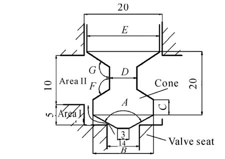
Figure 1.The structure of the poppet valve
2.2.Geometric model and grid division of the poppet valve
As shown in Figure 1,the fluid region was presented and the 3D design analysis software I-deas was adopted to establish the poppet valve model according to the given dimensions,and this model is meshed by a tetrahedral grid.Since the values of velocity and pressure are small at the inlet and outlet region,coarse grid was used at these two regions.Because there exist the throttle effect around the valve opening region,the pressure gradient and the change of velocity are relatively large,the grid of this model has been conducted the preliminary refinement and a local refinement at the export corner.Then,the grid model of poppet valve is imported into the fluid analysis software Star-CD and is analyzed by CFD[5-6].
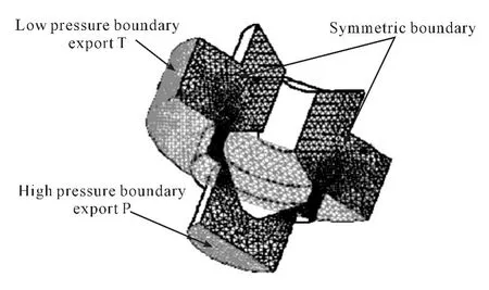
Figure 2.Boundary conditions of the poppet valve model
2.3.Analytical conditions of the poppet valve
For the present numerical simulation model,there are some assumptions as follows:first,the poppet valve is an ideal valve,i.e.,the valve cone and the valve sleeve fits accurately with no radial clearance between them;second,the fluid is incompressible,constant properties Newton fluid;third,both the effect of fluid gravity and internal fluid heat transfer are ignored in the valve cavity;fourth,the parameters of fluid properties are shown in Table 1;fifth,the boundary conditions are shown in Figure 2[7-8].
Table 1.Physical parameters offlow medium(40℃±1℃)
3.Effect of cone neck diameter on the flow characteristics of the poppet valve
If the cone neck diameter D changes from 4 mm to 14 mm with incensement 2 mm,the velocity distribution and pressure distribution of poppet valve could be obtained with different valve opening by CFD analysis.Through the integration of velocity distribution at given valve opening,the flow curve(as shown in Figure 3)and flow coefficient curve(as shown in Figure 4)could be obtained at the different valve opening.
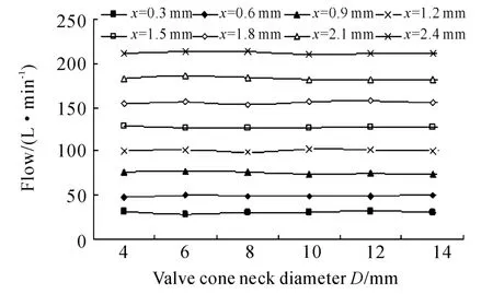
Figure 3.The flow curve
It could be seen from Figure 3 that the change of valve cone neck diameter D will not cause significant changes of the flow for a given valve of valve opening x.
Based on the information shown in Figure 4,one could conclude that the change of valve cone neck di-ameter D will cause a small change for the flow coefficient at a given value of opening x.As shown in this figure,the flow coefficient is almost a constant 1.12 if the valve opening x is 0.3 mm,however,the flow coefficient is a constant 0.86 when the valve opening x is changed from 0.6 mm to 2.4 mm.
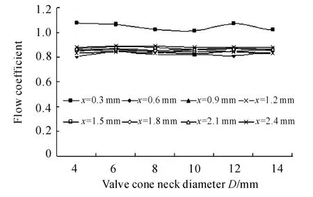
Figure 4.The flow coefficient curve
4.Effect of valve cone neck diameter on the cone resistance and steady flow force of the poppet valve
Based on the simulation results,the relationships between cone resistance and valve cone neck diameter D could be obtained as shown in Figure 5,and the relationships between steady flow force and valve cone neck diameter D as shown in Figure 6.
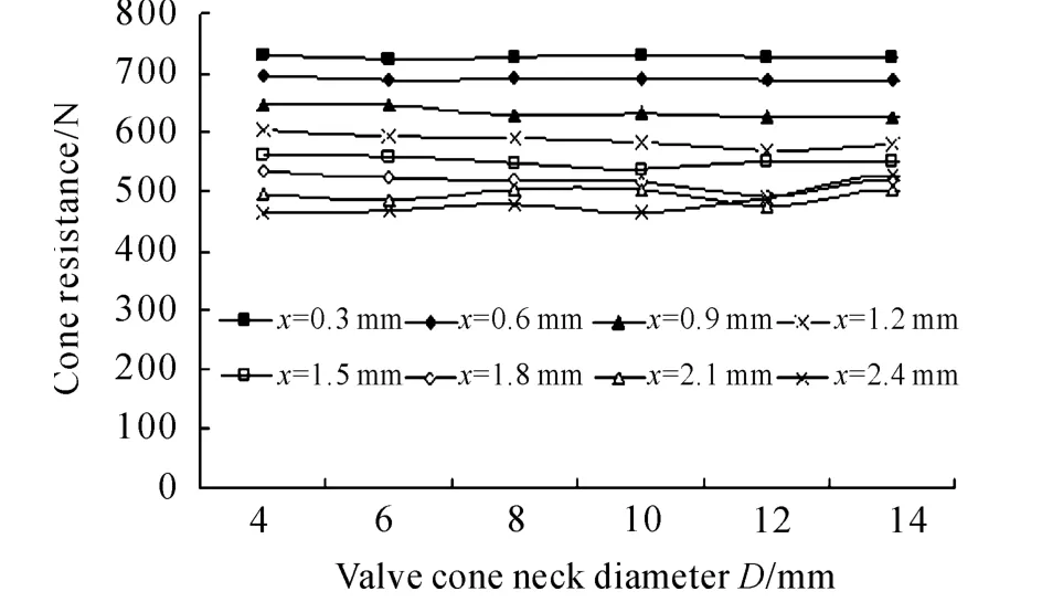
Figure 5.The cone resistance curve
It could be seen from Figure 5 that the value of cone resistance gets decreased with the increase of valve opening x for a given valve cone neck diameter D.When the value of valve opening x is small,the cone resistance is almost a constant for different values of valve cone neck diameter D,and once the value of opening x and the valve cone neck diameter D are big,the cone resistance will be obviously changed at a certain range.
From Figure 6,one could conclude that steady flow force gets increased with the increase of valve opening x for a given valve cone neck diameter D.Once the value of valve opening x is small,the change of valve cone neck diameter D will not cause significant change of the steady flow force;however,once the value of opening x and the valve cone neck diameter D are big,the steady flow force will be changed obviously within a certain range.
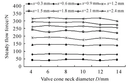
Figure 6.The steady flow force curve
5.Conclusion
By using the CFD model,the fluid flows within hydraulic poppet were obtained at the different value of valve cone neck diameter D.Based on the simulation results,the following conclusions could be drawn:the change of valve cone neck diameter D wil not cause signigicant change for the mass flow rate and the flow coefficient is almost a constant value around 0.86 at a given value of valve opening;The valve cone neck diameter D does not play an important role on the cone resistance and steady flow force.The cone resistance gets decreased with the increase of valve opening x,however the steady flow force gets increased with the increase of valve opening x.
[1] Lu Yongxiang.Flow coefficient and dynamitic force of two cartridge valve[J].Hydraulic pneumatic and seals,1983.
[2] Shi Jinyan.Study on Flow Rate and Steady Flow Force of Hydraulic Combination Valve Based on CFD[J].Applied Mechanics and Materials,2014(477-478):173-176.
[3] Liu Xiaohong,Ke Jian.Evaluation of noise of hydraulic cone valve based on computational fluid dynamics analysis[J].China Mechanical Engineering,2007,18(22):2687-2689.
[4] Xu Fuling.Hydraulic and pneumatic drive[M].Beijing:Mechanical Industry Press,2000.
[5] Wang Fujun.The second edition of the computational fluid dynamics analysis[M].Beijing:Tsinghua University Press,2005.
[6] Joe F T.Numerical grid generation[M].Elsevier Science Publishing Co.,Inc.,1995.
[7] Bernad S,Resiga R S,Anton I,et al.Vortex flow modeling inside the poppet valve chamber[Z].161-176.
[8] Yu Kaiyuan,Sheng Jingchao.Discussion on the direction of the inner flow poppet valve steady-state fluid force[J].Hydraulic and Pneumatic Drive,2006(10):26-28.
猜你喜欢
中国造纸(2022年9期)2022-11-25
中国造纸(2022年8期)2022-11-24
现代城市轨道交通(2022年11期)2022-11-21
中老年保健(2022年5期)2022-08-24
中老年保健(2022年6期)2022-08-19
少先队活动(2022年4期)2022-06-06
安徽医学(2022年5期)2022-05-21
湘潮(上半月)(2019年5期)2019-05-22
铁道通信信号(2018年11期)2019-01-19
铁道通信信号(2016年12期)2016-06-01
