
发动机缸体曲轴孔精加工专用夹具设计与研究*
2014-08-22 11:23肖铁忠苑春迎
机床与液压 2014年24期
肖铁忠,李 烜,黄 娟,罗 静,苑春迎
1.四川工程职业技术学院,四川 德阳 618000
2.包头市汇宏技术工程有限公司,内蒙古包头 014030
3.重庆理工大学汽车零部件先进制造技术教育部重点实验室,重庆 4000544.贵州詹阳动力重工有限公司,贵阳 550006
Since the processing requirements of engine are relatively high,while crankshaft hole machining is one of the three key processes for the engine,and its accuracy will directly determine the overall performance of the engine[1],an advanced and reasonable fixture system is very important for the machining precision and production efficiency[2-3].According to the current status of processing engine crankshaft hole,the first approach is that rough,semi-finishing and finishing processes will be separated on a dedicated machine,and then three times different positioning clamping are required.Since the clamping errors will inevitably exist,the final positioning accuracy will be influenced,then the requirements of precision machining can not usually meet;another disadvantage is that the finishing process is usually completed at the precision machining centers,which often has high machining precision and low production efficiency.In order to solve the above-mentioned problems,this paper will concentrate on the study of crankshaft hole semi-finishing and finishing in a process,i.e.,a special fixture will be designed and the semi-finishing and finishing of crankshaft hole will be completed by a single setup.Therefore,it will not only improve the machining accuracy and reduce labor intensity,but also meet the requirements of mass production efficiency.
1.Workpiece accuracy requirements and determined processes
1.1.Workpiece parameters and accuracy requirements
The main parameters of the workpiece and accuracy requirements is as follows:Name:Q465 cylinder;Dimensions:311×298×223;Bore diameter:5 × Ф5;Workpiece material:HT250(crank hole cover),aluminum alloy(crankshaft hole base body);Hardness:HB170~241(cast iron);workpiece weight:30 kg.As shown in Figure 1,the processing content and the accuracy requirements are presented.
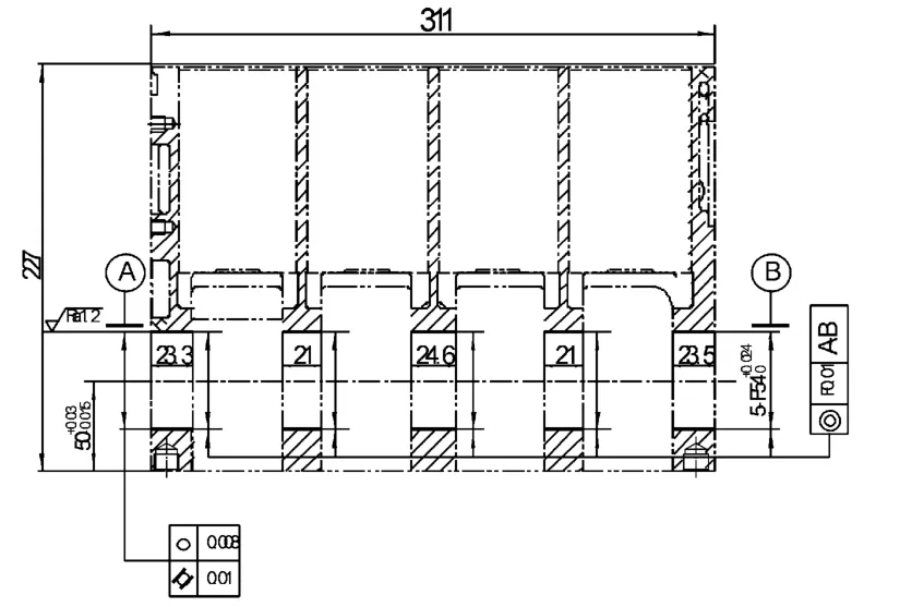
Figure 1.Technical drawings
1.2.To determine the process
Boring operation is generally used to make the crankshaft hole.In this paper,since the rough boring process of workpiece has been completed,a special fixture is adopted by a single setup to accomplish the semi-fine boring and fine boring process of crankshaft hole[4].Semi-fine boring and fine boring processes use the CBN tools;cutting speed is 120 m/min,and boring spindle speed is 708 r/min;tool feed speed is 0.06 mm/r;semi-fine boring unilateral margin is 0.5,and fine boring single unilateral margin is 0.1;cycle time is 2.3 min/piece[5].
1.3.To determine the Datum
Cylinder bore rough boring and fine boring processes,which are ahead of boring crankshaft hole process,use bottom surface and craft pin hole for positioning.Cylinder bore honing process,which is behind of boring crankshaft hole process,also use bottom surface and craft pin hole for positioning.Following the above-mentioned benchmark principles,this process also uses the same methods to determine the bottom surface and locate the pin hole.Following the datum principles,this boring process also use the bottom surface and craft pin hole for positioning.As shown in Figure 2,it presents the process locating datum.The bottom surface of the cylinder body is used as the first locating datum;craft pin hole near the rear end of the cylinder body is used as the second datum,and locating dowel pin is short cylindrical;craft pin hole near the front of the cylinder body is used as a third datum,and locating dowel pin is short argyle[6-7].
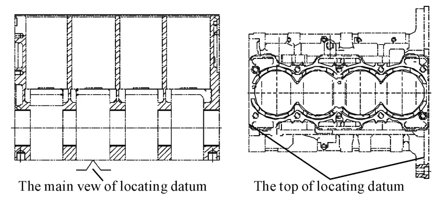
Figure 2.Locating datum schematic diagram
2.Design of special fixture system
Fixture system consists of specific folder,boring mold and other components,as shown in Figure 3.
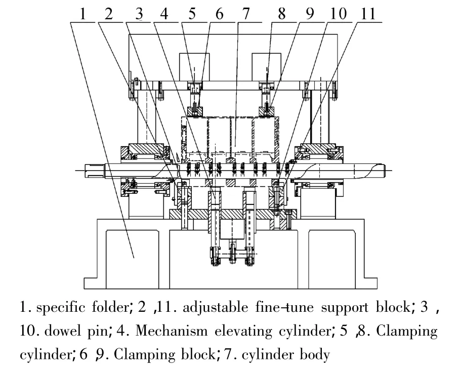
Figure 3.Fixture schematic diagram
2.1.Design of positioning mechanism
Positioning method:two side pins;positioning principle:six positioning;locating pin programs:fixed the positioning pins.The positioning mechanism is shown in Figure 3.Adjustable fine-tune support blocks 2,11 and dowel pins of 3 and 10 consisted of two side pins positioning mechanism.
Due to the manufacture accuracy,there is a gap between craft hole and dowel pin.Therefore,the positioning mechanism has a positioning error,as shown in Figure 4.
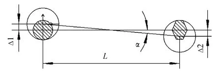
Figure 4.Positioning error Schematic diagram
After positioning,the maximum angle error of workpiece could be evaluated by Eq.(1).
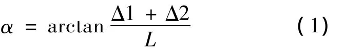
Where,Δ1 is the largest gap between location center of cylindrical pin and location center of craft hole;Δ2 is the largest gap between location center of the argyle pin and location center of craft hole;Δ1+Δ2 is the value of displacement error;L is the distance between cylindrical pin and argyle pin.All the values ofΔ1,Δ2 and L could be measured actually.
2.2.Clamping mechanism
This design used pneumatic clamping.After the workpiece is accurately positioned,the appropriate clamping force will be selected to overcome the vibration and overturn torque generated during cutting.The clamping mechanism is shown in Figure 5.Once the workpiece is accurately positioned,the pneumatic cylinder 1,7 will push the clamping rod 3,9 and clamping plates 5,11 to clamp the workpiece driven by guide bar 4,10.
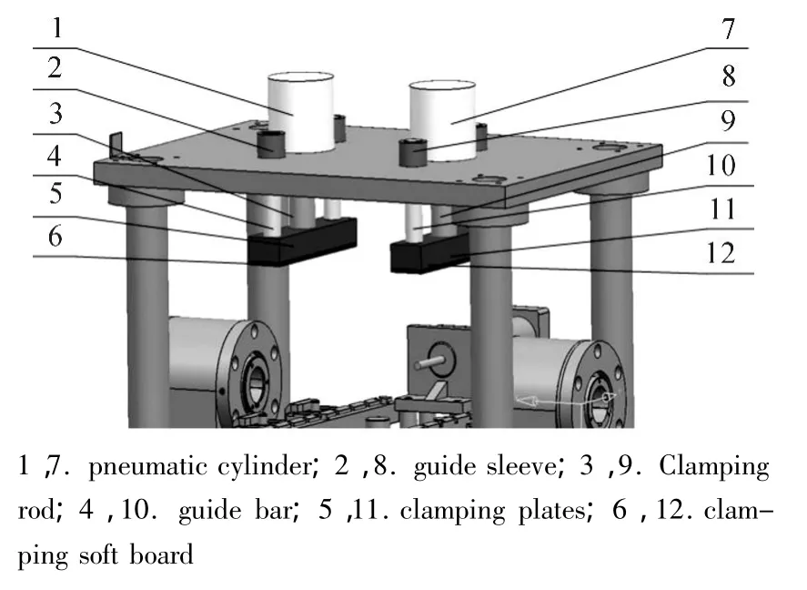
Figure 5.Clamping mechanism
2.3.Boring mold
As shown in Figure 6,the boring mode structure is presented.
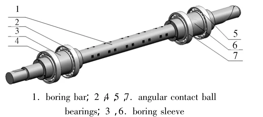
Figure 6.Boring mode structure
Boring mode structure is the external roll structure,and there exists an axial relative movement and no relative rotation between the boring bar and boring sleeve.Outside the boring sleeve,there equipped with angular contact ball bearings,and the boring sleeve will rotate with the boring bar.When the machine is working,work federate of boring bar is low,and there only exist relative movement between the boring sleeve and the boring bar,and then boring bar will not be heated due to the rapid friction,so it will not appear“killed”phenomenon of boring bar system.Angular contact ball bearings are necessarily preloaded,support stiffness throughout the boring bar will be greatly improved.
There is relative movement between the boring bar and boring sleeve,i.e.,a gap exits between them.This gap will lead radial movement of boring bar in the boring process,then affect processing roundness and cylindrical.If the gap is too big,processing precision may fail to meet the requirements;if the gap is too small,there may result in“killed”boring bar due to high-speed rotation boring sleeve in the process.Therefore,the gap between the boring bar and boring sleeve needs to be chosen as a reasonable value.In fine boring process,the minimum clearance value between the straight boring bar and the boring sleeve is recommended as from 1/5 to 1/6 of the corresponding processing site tolerances.The maximum gap should be less than 1/3 of the corresponding processing site tolerances[8].
3.Boring bar system analysis
3.1.Boring bar modal analysis
The geometrical model and mesh are shown in Figure 7.In order to solve this problem,the model has to be simplified and some assumptions will be made as follow:small structures such as chamfer and helical surfaces will be ignored,and clearance groove is treated as an entity;single row angular contact ball bearings are set as only bear radial load,and this ball bearings are simplified into springs;the density of boring sleeve and boring bar is set to be the same,and boring sleeve is treated as additional distribution quality of boring bar;spindle speed is low,the bearing stiffness is treated as a constant.
Boundary conditions are set as follows:zero displacement constraints are the only load in modal analysis,and the results are shown in Figure 8.
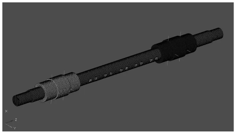
Figure 7.Finite element mesh model of boring bar
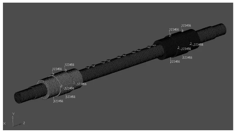
Figure 8.Modal analysis
Former sixth-order natural frequencies and corresponding mode shapes of boring bar are shown in Table 1,in which it shows that the minimum natural frequency of the boring bar is 370.5 Hz that is much greater than the excitation frequency 11.8 Hz during spindle operation.Therefore,the resonance phenomenon will not be generated.
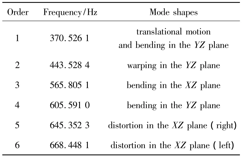
Table 1.Boring bar natural frequencies and mode shapes
3.2.Calculate bearing stiffness
In this paper,the experience of the formula that Lin Song summed up in 1982 is used to calculate the stiffness of angular contact ball bearing.

Where,K0is zero clearance angular contact bearing stiffness(N/μm);Fris the bearing radial load(N);d is the bearing diameter(mm).The selected bearing model is7014AC/P4,d=70 mm;load Fr=200 N.By using Eq.(3),the stiffness of angular contact ball bearing could be calculated,K0=16.362 N/μm,and for double support structure,the corresponding bearing stiffness is 32.724 N/μm which is as much as twice of K0.
3.3.Effect of bearing stiffness on the boring bar
Bearing stiffness is not a fixed value,and it has a non-linear relationship with suffered load and preload.The arrangement of angular contact ball bearing is constant,and bearing stiffness values are taken as 0.327 24,3.272 4,32.724,327.24,3 272.4,32 724 N/μm,respectively.The first natural frequency of boring bar variation is shown in Figure 9.
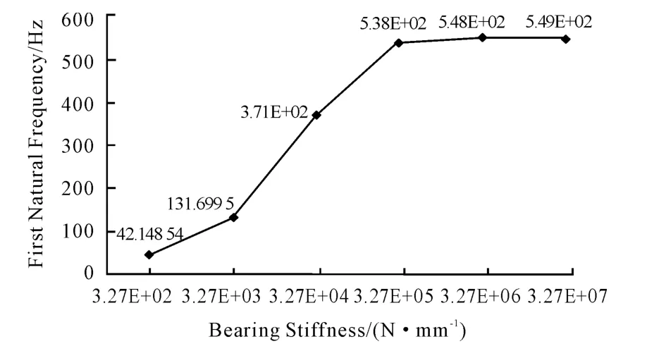
Figure 9.Effect of bearing stiffness on the boring bar stiffness
As shown in Figure 9,the natural frequency of the boring bar system gets increased with the increase of bearing stiffness.When bearing stiffness reaches a certain value,the natural frequency of the boring bar system will approach to a certain value.It could be seen that the bearing stiffness has an important influence on the dynamic properties of boring bar system.Therefore,it is very important to obtain the right bearing stiffness by adjusting the bearing preload in real applications.
4.Conclusion
In this paper,a special fixture system is suc-cessfully developed,which will effectively improve the machining accuracy and production efficiency.Through the actual operation and test,the accuracy of machining tools meets or exceeds the expected requirements,and the production efficiency is up to 2.3 min/pc.Furthermore,due to the high automation degree of this fixture system,the labor intensity could be greatly reduced.Currently,this technology has been applied in multiple production lines of a number of machinery manufacturing companies in Chongqing,and obtained some good feedbacks.
[1] Li Wen-di,Wang He-zeng,Yang Hong-mei.Development of NC Machine for Finish Milling Cylinder Bottom& Drilling and Reaming Pin Hole[J].Modular Machine Tool& Automatic Manufacturing Technique,2013(6):124-129.
[2] Wu Min,Zhuang Dong-hai.Technical Processing Analysis and Special Fixture Design Based on Panel Parts[J].MACHINE TOOL & HYDRAULICS,2013(8):43-46.
[3] Liu Xu,Zhu Xue-chao,Li Hong-wei.Machining Techniques Rules and Drilling Fixture Design on Typical Shell Parts[J].Coal Mine Machinery,2012(8):125-126.
[4] Luo Jing;Xiao Tiezhong;Gong Wenjun;Yuan Chunying.Special boring machine design for processing of the crankshaft hole of automobile engine cylinder[J].Manufacturing Technology & Machine,2013(9):76-79.
[5] Luo Jing,Xiao Tiezhong,Gong Wenjun,et al.Semi-intensive and fine boring processing of dual-metal crankshaft hole of the engine cylinder[J].Manufacturing Technology & Machine,2013(8):101-103.
[6] Yuan Chunying.Design and research of automobile engine cylinder dual metal crankshaft hole CNC precision boring machine[D].Chongqing:Chongqing University of Technology,2012.
[7] LI Ji,LAI Yu-huo,FENG Yue-xia.Design of special fixture for drilling hole of engine cylinder[J].Modular Machine Tool& Automatic Manufacturing Technique,2013(3):108-110.
[8] Peng xiaogan.Design and research of dedicated high-precision three-axis boring machine tool[D].Dalian:Dalian University of Technology,2009.
[9] Miao Xiaopeng,Ma Jianghu,Su Huali.Processing method and fixture design of the cross axis aperture in differential shell[J].Manufacturing Technology & Machine,2012(7):59-61.
猜你喜欢
疯狂英语·新读写(2022年1期)2022-11-23
装备制造技术(2021年1期)2021-05-21
哈尔滨轴承(2021年4期)2021-03-08
少儿美术(快乐历史地理)(2020年6期)2020-10-27
制造技术与机床(2017年7期)2018-01-19
制造技术与机床(2017年10期)2017-11-28
制造技术与机床(2017年9期)2017-11-27
卫生职业教育(2014年16期)2014-05-16
河南科技(2014年8期)2014-02-27
中国工程咨询(2010年7期)2010-02-16
