
基于热成像技术的牛舍围护结构传热阻测试方法
2018-01-09 01:59施正香王朝元
农业工程学报 2017年24期
曹 哲,施正香,安 欣,王朝元
基于热成像技术的牛舍围护结构传热阻测试方法
曹 哲1,2,施正香1,3※,安 欣1,2,王朝元1,3
(1. 中国农业大学水利与土木工程学院,北京 100083; 2. 农业部设施农业工程重点试验室,北京 100083; 3. 北京市畜禽健康养殖环境工程技术研究中心,北京 100083)
针对传统的接触式传热阻测试方法对测试场合要求高、操作复杂、操作时间相对较长等难以应用于环境较为恶劣的畜禽舍问题,该文引入热成像技术,开展了黑龙江地区2种不同类型牛舍的围护结构热特性参数现场测试,获得了基于热成像法和传统接触式测试法下牛舍墙体、屋面、门窗的特征温度值。在此基础上,计算了牛舍围护结构材料的传热阻,并与相应建筑材料的传热阻理论计算值进行了对比分析。结果表明,对于墙体、屋面等围护结构,2种方法所获得的传热阻测试值与理论计算值的偏差小于15%;对于围护结构窗体和门,2种方法所获得的传热阻测试值与理论计算值的偏差在20%~30%之间;虽然热成像法和接触式测试法现场实测值与理论计算值之间都存在偏差,但因现场测试能综合材料老化、脱落、受潮和施工质量等实际情况,相对而言实测值的可信度更高;但综合考虑2种方法,热成像法的操作简单、便捷,可以很好地用于畜禽舍围护结构的热工性能评价。
墙体;传热阻;热成像仪;接触式测试法;现场测试
0 引 言
建筑围护结构热工性能是决定舍内热环境的重要因素,影响着舍内温度高低和分布的均匀性[1]。相比于人居环境,畜禽舍内湿度大、有害气体浓度高,温度分布不均,粉尘颗粒物含量高,长期积累会引起建筑围护结构材料热工性能的改变。如何在现场环境下进行材料传热阻的准确测定,对设计畜禽舍围护结构,获得良好的舍内环境具有重要意义。
传热阻是确定建筑围护结构保温性能的重要参数,也是建筑热舒适性的重要指标,对舍内热环境状况及加热或降温能耗影响极大。传热阻的大小不仅取决于材料自身的类型,厚度及每层材料的密度,还与材料所处的外界环境因素紧密相关,包括风速、风向、太阳辐射以及外界环境温度分布[2-5]。传热阻值越大,材料的保温性能越好。现有的材料传热阻值标定方法大部分均是在气候试验室内完成[6],由于建筑材料传热阻的测定会受多种因素的共同影响,准确反映材料热工性能具有一定的难度,经常会出现材料加工制造商所反映的材料传热阻值与真实值不符[7]。目前,用于建筑结构传热阻的测试方法主要有接触式测试法(非破坏性测试法)及直接取样测定法(破坏性测试法)2种方法[8-9]。该2种主要缺点是:对测试环境要求严格,操作复杂,能耗高,测点孤立。近年来,热成像法作为热故障诊断和测试领域的先进手段之一,已被广泛应用于各行各业[10-16]。相比于上述2种测试方法,热成像法可通过拍摄热谱图进行直观、无损测试,且测试速度快、操作简单,能对物体结构或建筑的保温性、气密性、施工缺陷等进行多目标测试[17-20]。
本试验采用热成像技术,通过对中国东北地区2种不同建筑形式牛舍的围护结构热特性参数进行测定,对比传统接触式测试法和热成像法现场测定围护结构材料的传热阻值,结合理论计算值评价热成像法的准确性和可靠性,以期为牛舍围护结构保温性能的现场评价提供新思路。
1 传热阻计算原理
1.1 热成像法传热阻计算
热成像仪能够快速准确地测量物体表面的温度,在使用其测定围护结构热工性能时,只能测得墙体表面的温度,无法客观评价不同建筑围护结构的保温性能,实际测试时需要结合热平衡理论对建筑壁面传热阻进行有效估算。
结合一维稳态导热条件下的导热微分方程,考虑对流换热和辐射换热并存的复合边界条件,推导出利用热成像仪测试参数计算传热阻1的公式:

式中1为热成像法计算得到的传热阻值,m2·K/W;w,ref,in,out分别表示墙体内表面温度、墙体反射温度、室内环境温度和室外环境温度,K;表示材料表面发射率;表示斯蒂芬-玻尔兹曼常数,5.67×10-8(W/m2·K4);in为内墙体表面对流换热系数,W/(m2·K)。
分析知冬季建筑外墙的室内壁面散热模型可简化为平板壁面自然对流传热,关于这种传热模型,Churchill等在整理大量文献数据的基础上推导出平板自然对流传热准则关联式[21],如下:


式中为无量纲努塞尔数,表示对流换热强度的准则数;为传热面的几何特征长度,m;为流体对流换热系数,W/(m2·K);为静止流体的导热系数,W/(m·℃);为无量纲瑞利数,为无量纲普朗特数,为体积热膨胀系数,1/K;为当地重力加速度,m/s2;为平板与竖直面的夹角,°;为热扩散率,m2/s;ν流体运动粘度,m2/s;T,T,∞分别为竖直表面温度,特征温度,边界层外空气温度,K。
通过上式(2),带入现场测得相关特征值以及查得相关理论参数即可计算出墙体、屋面等结构各自内表面对流传换热系数in。此外,热成像仪测试物体表面的温度场分布和测定精度还要考虑来自自身参数设定与外界环境状态的影响[22-23],其中环境反射温度ref和发射率对其影响最大。
1.1.1 反射温度(ref)
根据热成像仪测定反射温度原理[24],ref应为固定在被测试样表面的发射率接近于1的褶皱铝箔的表面温度,可通过如图1所示的方法间接测得。具体做法为:将反射铝箔平行于试样表面放置,将热成像仪的表面发射率设定为1,保持热成像仪和试样适宜的距离(保证成像仪中的物像清晰),测定铝箔表面温度3次,求得材料表面的平均反射温度ref。

图1 反射原理测量材料表面反射温度
1.1.2 材料表面发射率()
被测试样的表面发射率(),不仅取决于材料本身,还与材料表面粗糙度、环境温度、湿度及材料形状等有关[25]。现场测试中,试样表面的发射率可依据热辐射基本原理(图2)[26]进行计算。

注:ε为物体表面发射率,τ为大气透射率,T为温度值,W为辐射能,下标obj, ref, atm 分别表示试样、反射和空气环境。
首先,需要确定热成像仪所接收的总辐射能,即
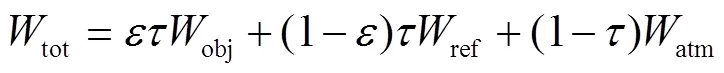
式中tot为热成像仪接收总辐射能,W/m2;obj为目标辐射能,W/m2;ref为周围环境的反射辐射能,W/m2;atm为大气辐射能,W/m2;是物体表面发射率;为大气透射率。
由于舍内大气透射率接近于1[27],取=1,化简上式得到物体表面的发射率

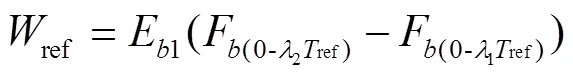
式中ref,obj可由给定温度下某波段内黑体辐射力计算公式得到


1.2 其他测试方法的传热阻计算
通常,围护结构传热阻计算主要采用现场接触式测试法,或按照国际标准方法(BS EN ISO 6946:1997)得到。接触式测试法是依据围护结构材料两侧对流和导热传热原理建立热平衡,由此推导出基于热电偶测试围护结构表面温度的传热阻2计算公式,即

国际标准中关于围护结构传热阻的理论计算公式如下
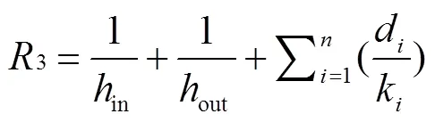
式中2,3分别为利用接触式测试法和理论计算方法得到的围护结构传热阻,m2·K/W;out为围护结构外部墙体的表面换热系数,W/(m2·K);d表示材料层的厚度,m;k表示材料层导热系数W/(m·K);out的值也可以通过对流传热关联式(2)带入相应特征参数求得。材料层导热系数可以从相关标准中查得[28]。
2 材料与方法
2.1 试验对象
分别选择黑龙江密山市密闭式和双城市卷帘式泌乳牛舍各1栋为测试对象,其围护结构材料见表1。

表1 牛舍材料
2.2 测试仪器和方法
试验中,主要测试室内外温湿度,以及围护结构的表面温度。
2.2.1 室内外空气温湿度测试
采用APresys179-TH温湿度传感器感器(量程:温度:−40~100 ℃,湿度:0~100%RH,测量精度:±0.3 ℃,±3%RH),测试前对各传感器进行统一标定。
2.3.2 围护结构壁面温度测试
使用S6手持式热成像仪(量程:−20~650 ℃,测量精度:±2 ℃,波长范围8~14m)和贴片式T型热电偶(量程:−200~350 ℃,精度±0.5 ℃,响应时间3 s)测量,热电偶温度用Agilent 34972A数采仪采集。
1)热成像法
热成像仪的视场角为25°×19°,垂直视角为19°,现场测量侧墙围护结构的垂直高度为4 m, 经几何计算,拍摄距离应为12 m。采集舍内围护结构表面温度时,手持热成像仪沿牛舍东西向进行测量,依据牛舍尺寸等间距采取南北两侧红外热谱图像各7张。红外热谱图像采集与热电偶测牛舍围护结构表面温度同时进行,每栋牛舍测量之前需要根据现场环境参数对发射率、反射温度、湿度、环境温度、测试距离进行设定。环境温度测试样点选取牛舍内东西和南北方向的6个测点,仪器安装在与牛体站立时等高的1.5 m位置,测点布置如下图3所示。

图3 试验测点布置
热成像仪设置参数中发射率采用现场试测法,步骤如下:
①利用T型热电偶采用接触式测试法测量目标表面温度obj,由公式(6)求得obj;
②利用1.1.1中测得环境反射温度ref,由公式(5)求得ref;
③设置热成像仪发射率,使=1,读出热成像仪中目标表面温度obj,由公式(6)求得obj,由于在舍内,=1,由公式(3)得tot=obj;
④ 依照上述步骤将测得数据obj、ref、tot带入公式 (4)计算发射率;
2)接触式测试法
采用传统测试材料表面传热阻的方法,围护结构表面温度采用贴片式T型热电偶测试,并利用Agilent 34972A数据采集仪进行数据的连续采集。测试时间选择在利用热成像仪进行测试的时间段(每天17:00-20:00时),与红外热谱图像采集同时进行。测试方法为:在待测区热成像仪所采集的单张红外图像所对应的区域范围内布置3组贴片式T型热电偶,将Agilent 34972A数据采集仪的时间间隔设置为每30 min记录1次。
2.3 测试时间选择
本试验于2016年1月份进行。由于太阳辐射以及环境风速[29]对围护结构表面温度和热成像仪测温精度有较大影响,为确保试验期间所测结果的准确性,围护结构的内外温差至少保证为10 ℃[30-32]。因此,需要首先确定一天当中环境温度基本处于稳定状态的时间区间。试验前通过对所在地的室外温度进行连续5 d的监测,得到17:00-20:00时间段内外界环境温度波动较小且稳定,加之此时间段试验地受太阳辐射的影响比较小,故认为该段时间牛舍围护结构的热量传递方式为稳态传热,满足传热阻计算要求。因此传热阻测试选择在17:00-20:00时段内进行。监测试验期间,外界环境温度的变化情况,如图4所示。

图4 外界环境温度日变化
2.4 数据处理
利用热成像分析软件RDIRs对测得的热谱图像进行处理提取有用的温度信息,采用spss20.0软件进行数据处理分析,进行独立样本检验。
3 结果与分析
3.1 围护结构不同部位的传热阻值
按照理论计算、热成像法、接触式测试法,对所测牛舍围护结构的侧墙体等部位的传热阻值进行了计算,结果见表2。

表2 不同测试方法下被测牛舍围护结构不同部位的传热阻值
注:不同小写字母表示处理间数据差异显著(<0.05);不同大写字母表示处理间数据差异极显著(<0.01)。
Note: Different lowercase and uppercase indicate significant difference and extremely significant difference among treatments, at 0.05 and 0.01 level, respectively.
3.1.1 理论计算值与实测值的差异分析
由表2可知,热成像法和接触式测试法测得牛舍围护结构不同部位的传热阻值均小于理论计算值。产生此结果的原因为:围护结构在使用过程中,材料老化、受潮、腐蚀等综合作用使其热阻值相对于初始值有所降低[33]。而牛舍门、窗在使用的过程中受外界环境因素干扰更大(磨损严重),因此其实测值与理论计算值的差异更大。同时,日常管理中操作不当造成结构破损等因素也可能引起传热阻值减小,结构的保温性能降低。
3.1.2 热成像法和接触式测试法的差异比较
由表2可得,利用热成像法测得围护结构各部位的传热阻值与接触式测试法测得值之间存在差异。其中密闭牛舍的屋顶和卷帘牛舍的屋顶在2种方法下测得值差异极显著(<0.01);密闭牛舍的侧墙体、门、窗和卷帘牛舍的矮墙、卷帘、侧墙体、门在2种方法下测得值差异比较显著(<0.05)。
接触式测试法在原理上仅考虑了传导和对流传热过程,而热成像法不仅考虑了上述2种传热过程,还包含了辐射传热过程[34],因此测得结果会存在一定的差异。同时,由于2种方法的测试手段不同,所用测试装置不同,测试结果会受装置测量精度的影响,因而也会造成一定的偏差。
3.1.3 测试值与理论计算值吻合度比较
为进一步解析热成像法和接触式测试法结果的可靠性,本文依据相对偏差百分比,对不同方法下的传热阻值与理论计算值进行了比较,结果如图5。

图5 不同热阻测试方法吻合度对比
由图5可以看出,2种方法测得传热阻值与理论计算值均存在偏差,接触式测试法测得值与理论计算值的吻合度更高。在测定牛舍主要围护结构部位侧墙体、屋顶、矮墙、卷帘的传热阻值时,2种方法的偏差百分比均小于15%;在测定围护结构窗体和门的传热阻值时,2种方法均与理论计算值存在较大偏差,偏差百分比在20%~30%。因此,2种方法用于测试牛舍主要围护结构材料传热阻,结果均比较可靠。
与接触式测试法相比,热成像法测点数量多,可有效补偿由于单个测点数据不稳定波动所引起的误差,采用所有点计算传热阻值所得结果会更加符合材料在真实环境下的传热阻值。同时,由于接触式测试法需要选择测点、布置测点,而且需经过长时间待测试参数稳定后才能记录数据,如果考虑现场测试操作的便捷性,热成像法的优势更加明显,尤其是在湿度大、有害气体浓度高,粉尘颗粒物含量高,密闭性差,门窗洞口较多的畜禽舍内。综合以上因素,热成像法更适合于复杂环境下畜禽舍围护结构传热阻的现场测试。
3.2 密闭牛舍和卷帘牛舍围护结构的热特性分析
由于牛舍围护结构的热特性与组成围护结构的材料有关,因此不同结构部位门、窗、墙体的材料在围护结构组成中所占比例不同,围护结构的整体热特性也不同。基于表2测得的结果,本文又对密闭牛舍和卷帘牛舍围护结构的整体热特性进行了分析。针对本试验,由于侧墙、山墙、屋面等围护结构由不同传热阻值的材料复合而成,进行围护结构传热阻计算时,要考虑组合材料的平均传热阻值,其计算方法如下。
墙体:

屋面:

式中:4,8为墙体、屋面平均传热阻,m2·K/W;1,2,3为主墙体、门、窗面积,m2;5,6,7主墙体、门、窗传热阻,m2·K/W;4,5为主体屋面、采光板面积,m2;9,10为主体屋面、采光天窗传热阻,m2·K/W。
由公式(9)、(10)计算不同测试方法下的围护结构平均传热阻值,结果见表3。对比2栋牛舍围护结构(侧墙、山墙、屋面)的冬季低限传热阻值和现场实测值、理论计算值发现,对于密闭牛舍,墙体和屋面传热阻值均高于冬季所要求的低限传热阻值,牛舍保温性能符合设计要求。而对于卷帘牛舍,屋面传热阻符合冬季低限传热阻值的要求,但主要围护结构侧墙(组成为卷帘和矮墙)的传热阻值不符合墙体冬季低限传热阻值的设计要求。因此,在东北地区,密闭牛舍结构较卷帘牛舍结构更能满足牛舍保温设计的要求(实际传热阻值高于冬季低限传热阻值)。

表3 不同方法得到牛舍围护结构热阻值
4 结 论
1)热成像法和接触式测试法均考虑了材料在现场环境下因老化、脱落、受潮和施工质量等问题对传热阻值的影响。因而测得牛舍围护结构不同部位的传热阻值小于理论计算值。
2)与热成像法相比,利用接触式测试法计算传热阻值与理论计算值的吻合度更高。在测定牛舍主要围护结构部位侧墙体、屋顶、矮墙、卷帘的传热阻值时,2种方法的偏差百分比均在15%以内;在测定围护结构窗体和门的传热阻值时,2种方法的偏差百分比在20%~30%。
3)对比接触式测试法,热成像法计算原理包含了围护结构材料的辐射传热过程,理论基础更加完善。同时,考虑到现场操作环境对测试值准确性的影响,热成像法的操作更加便利。综合以上因素,热成像法更适合于复杂环境下畜禽舍围护结构传热阻的现场测试。
[1] 国家奶牛产业技术体系. 中国现代农业产业可持续发展战略研究[M]. 北京:中国农业出版社,2016.
[2] Hagishima Aya, Tanimoto Jun. Field measurements for estimating the convective heat transfer resistance at building surfaces[J]. Building and Environment, 2003, 38(7): 873-881.
[3] Shao Jiantao, Liu Jing, Zhao Jianing, et al. A novel method for full-scale measurement of the external convective heat transfer resistance for building horizontal roof[J]. Energy and Buildings, 2009, 41(8): 840-847.
[4] Irving A D, Dewson T, Hong G, et al. Time series estimation of convective heat transfer resistance[J]. Building and Environment, 1994, 29(1): 89-96.
[5] Emmel Marcelo G, Abadie Marc O, Mendes Nathan. New external convective heat transfer resistance correlations for isolated low-rise buildings[J]. Energy and Buildings, 2007, 39(3): 335-342.
[6] Cucumo M, De Rosa A, Ferraro V, et al. A method for the experimental evaluation in situ of the wall conductance[J]. Energy and Buildings, 2006, 38(3): 238-244.
[7] Desogus Giuseppe, Mura Salvatore, Ricciu Roberto. Comparing different approaches to in situ measurement of building components thermal resistance[J]. Energy and Buildings, 2011, 43(10): 2613-2620.
[8] Cabeza Luisa F, Castell Albert, Medrano M, et al. Experimental study on the performance of insulation materials in Mediterranean construction[J]. Energy and Buildings, 2010, 42(5): 630-636.
[9] Zarr R R. A History of testing heat insulators at the national institute of standards and technology[J]. Ashrae Transactions, 2001, 107(2): 661-671.
[10] Mccafferty Dominic J. The value of infrared thermography for research on mammals: Previous applications and future directions[J]. Mammal Review, 2007, 37(3): 207-223.
[11] Kordatos E Z, Aggelis D G, Matikas T E. Monitoring mechanical damage in structural materials using complimentary NDE techniques based on thermography and acoustic emission[J]. Composites Part B Engineering, 2012, 43(6): 2676-2686.
[12] Gottschalk K, Mészáros Cs. IR thermometry for heat and mass transfer analysis of surface drying of fruit[C]//11th International Conference on Quantitative Infrared Thermography, Naples, Italy, June, 2012.
[13] Bagavathiappan Subramnaiam, Philip John, Jayakumar Tammana, et al. Correlation between plantar foot temperature and diabetic neuropathy: A case study by using an infrared thermal imaging technique[J]. Journal of diabetes science and technology, 2010, 4(6): 1386-1392.
[14] Lewandowski Witold M, Ryms Michał, Denda Hubert. Infrared techniques for natural convection investigations in channels between two vertical, parallel, isothermal and symmetrically heated plates[J]. International Journal of Heat and Mass Transfer, 2017, 114: 958-969.
[15] O’Grady M, Lechowska A A, Harte A M. Infrared thermography technique as an in-situ method of assessing heat loss through thermal bridging[J]. Energy & Buildings, 2016, 135: 20-32.
[16] O’Grady Małgorzata, Lechowska Agnieszka A, Harte Annette M. Quantification of heat losses through building envelope thermal bridges influenced by wind velocity using the outdoor infrared thermography technique[J]. Applied Energy, 2017, 208: 1038-1052.
[17] Bodnar J L, Candoré J C, Nicolas J L, et al. Stimulated infrared thermography applied to help restoring mural paintings[J]. Ndt & E International, 2012, 49: 40-46.
[18] Defer D, Shen J, Lassue S, et al. Non-destructive testing of a
building wall by studying natural thermal signals[J]. Energy and Buildings, 2002, 34(1): 63-69.
[19] Kylili A, Fokaides P A, Christou P, et al. Infrared thermography (IRT) applications for building diagnostics: A review[J]. Applied Energy, 2014, 134: 531-549.
[20] Bagavathiappan S, Lahiri B, Saravanan T, et al. Infrared thermography for condition monitoring-a review[J]. Infrared Physics & Technology, 2013, 60: 35-55.
[21] Churchill S W, Ozoe H. A Correlation for laminar free convection from a vertical plate[J]. Journal of Heat Transfer, 1973, 95(4): 540.
[22] Stewart M, Webster J R, Schaefer A L, et al. Infrared thermography as a non-invasive tool to study animal welfare[J]. Animal Welfare, 2005, 14(4): 319-325.
[23] Johnson Shylo R, Rao Sangeeta, Hussey Stephen B, et al. Thermographic eye temperature as an index to body temperature in ponies[J]. Journal of Equine Veterinary Science, 2011, 31(2): 63-66.
[24] Standard Test Methods for Measuring and Compensating for Reflected Temperature Using Infrared Imaging Radiometers: ASTM E 1862-97[S]. West Conshohoken: ASTM international, 2002.
[25] 杨永军,王中宇,张术坤,等. 基于多光谱测温优化的材料光谱发射率测量[J]. 北京航空航天大学学报,2014,40(8):1022-1026.
Yang Yongjun, Wang Zhongyu, Zhang Shukun, et al. Material spectral emissivity measurement optimized by multi-spectral temperature measured[J]. Journal of Beijing University of Aeronautics and Astronautics, 2014, 40(8): 1022-1026. (in Chinese with English abstract)
[26] Fokaides Paris A, Kalogirou Soteris A. Application of infrared thermography for the determination of the overall heat transfer resistance (U-Value) in building envelopes[J]. Applied Energy, 2011, 88(12): 4358-4365.
[27] 罗晓春,孙继银. 物体表面发射率的测量方法[J]. 自动测量与控制,2007(8):72-74.
Luo Xiaochun, Sun Jiyin. Method for measuring object surface emissivity[J]. Automatic Measurement and Control, 2007(8): 72-74. (in Chinese with English abstract)
[28] 民用建筑热工设计规范:GB/50176-1993[S].北京:中国计划出版社,1993.
[29] Church John S, Hegadoren P R, Paetkau M J, et al. Influence of environmental factors on infrared eye temperature measurements in cattle[J]. Research in veterinary science, 2014, 96(1): 220-226.
[30] Feuermann Daniel. Measurement of envelope thermal transmittances in multifamily buildings[J]. Energy and Buildings, 1989, 13(2): 139-148.
[31] Trethowen H. Measurement errors with surface-mounted heat flux sensors[J]. Building and Environment, 1986, 21(1): 41-56.
[32] Achenbach Paul R. Design of a calibrated hot-box for measuring the heat, air, and moisture transfer of composite building walls[J]. Thermal Performance of the Exterior Envelopes of Buildings, Proceedings-1, 1981: 308-324.
[33] Grinzato E, Vavilov V, Kauppinen T. Quantitative infrared thermography in buildings[J]. Energy & Buildings, 2010, 29(1): 1-9.
[34] 章熙敏,任泽霈,梅飞鸣. 传热学(第六版)[M]. 北京:中国建筑工业出版社,2014.
[35] 工业建筑供暖通风与空气调节设计规范:GB/50019-2015[S]. 北京:中国计划出版社,2015.
Evaluation on measure method of heat transfer resistance for enveloped structure of cattle barn based on infrared imaging method
Cao Zhe1,2, Shi Zhengxiang1,3※, An Xin1,2, Wang Chaoyuan1,3
(1.100083; 2.100083,; 3.100083,)
The heat transfer resistance of enveloped building structure plays an important role in the heat gain and heat loss of building environment. It is also a crucial index related to building thermal comfort. Compared with the housing conditions of residents, those conditions of housings for animals are more complex, which are filled with heavy moisture, highly toxic gases, and high-level dust. The accumulation of these factors can have a negative effect on the thermal performance on the surface material of building structure. For minimizing the heat loss of material, it is vital to accurately measure the material heat transfer resistance in the field environment. In recent years, the infrared imaging method, an advanced technology in the area of fault diagnosis and detection, has been widely used in various industries, such as the thermal performance test of enveloped structures on industrial and civil building. It has the distinct advantage on the portable and prompt detection of surface temperatures with the visualized thermal image. This article mainly focuses on the application of infrared thermal image technology in 2 different forms of cattle barns in northeast region. To determine heat transfer resistance of enveloped structure, the derivation of related heat transfer equation would be taken into account. Compared with the traditional method, the infrared imaging method is more reliable to evaluate the heat transfer resistance of the enveloped structure in the cattle barn. The hand-held infrared thermal imager was used to measure the surface temperature of enveloped structure with setting the view from center passageway towards the wall of the barn. The instrument was carefully calibrated to ensure the setting parameters (emissivity, reflection temperature, humidity, and so on) to be in the optimal conditions before the measurement. For the validation of the infrared image method, the environment temperature was also recorded by the T & RH sensors with 6 testing points in the north and south sides of the barn. The T thermocouples were installed at the height of 1.5 m (the same level as standing cattle) and automatically measured the enveloped structure temperature. A data acquisition system (Agilent 34972A) was applied for continuous data collection. The results showed that the thermal imaging method could be used for the detection of thermal properties in some places unavailable for the contact measurement, such as side walls, roof, and shutter. Compared with the theoretical value obtained from the theoretical calculation, these 2 methods both had a high agreement (absolute deviation percentage was basically within 15%). However, the detection of heat transfer resistance in windows and doors by these methods was not consistent (deviation percentage was between 20% and 30%). Thermal imaging technology made comprehensive use of the site environment parameters and the actual heat value of enveloped structures, which was affected by materials aging, falling off, damp air conditions, scene construction quality, and so on. Therefore, the result from infrared imaging method on the detection of the heat transfer resistance is acceptable and reliable. The results of heat transfer resistance with some conventional methods, such as formula deduction and correlation equations, were significantly influenced by the precision of the measuring instrument, some accidental errors, and limitation on the defects detection. Therefore, the infrared image technology can be an alternative method for the detection of thermal properties in the housing system for animal.
wall; heat transfer resistance; thermography; contact test method; field test
10.11975/j.issn.1002-6819.2017.24.031
S23
A
1002-6819(2017)-24-0235-07
2017-07-31
2017-12-09
现代农业(奶牛)产业技术体系(CARS-36);国家863课题任务(2013AA10230602)。
曹 哲,男,陕西安康人,主要从事畜禽养殖工艺与环境研究。Email:zhecao@cau.edu.cn
施正香,女,江苏启东人,教授,博士生导师,主要从事畜禽养殖工艺与环境研究。Email:shizhx@cau.edu.cn
曹 哲,施正香,安 欣,王朝元. 基于热成像技术的牛舍围护结构传热阻测试方法[J]. 农业工程学报,2017,33(24):235-241. doi:10.11975/j.issn.1002-6819.2017.24.031 http://www.tcsae.org
Cao Zhe, Shi Zhengxiang, An Xin, Wang Chaoyuan. Evaluation on measure method of heat transfer resistance for enveloped structure of cattle barn based on infrared imaging method[J]. Transactions of the Chinese Society of Agricultural Engineering (Transactions of the CSAE), 2017, 33(24): 235-241. (in Chinese with English abstract) doi:10.11975/j.issn.1002-6819.2017.24.031 http://www.tcsae.org
猜你喜欢
电子元件与材料(2022年11期)2023-01-10
山西电子技术(2022年2期)2022-04-22
空间科学学报(2020年6期)2020-07-21
空军工程大学学报(2020年6期)2020-03-26
中国科技纵横(2019年2期)2019-03-25
中学生数理化·教与学(2018年10期)2018-12-06
中华老年口腔医学杂志(2016年3期)2017-01-15
出版科学(2016年1期)2016-02-06
探测与控制学报(2015年4期)2015-12-15
自然资源遥感(2014年3期)2014-02-27
