
Measuring the flexibility matrix of an eagle's flight feather and a method to estimate the stiffness distribution∗
2019-08-06 02:07DiTang唐迪HaiZhu朱海WeiYuan袁巍ZhongyongFan范忠勇andMingxiaLei雷鸣霞
Chinese Physics B 2019年7期
关键词:雷鸣
Di Tang(唐迪), Hai Zhu(朱海), Wei Yuan(袁巍), Zhongyong Fan(范忠勇), and Mingxia Lei(雷鸣霞)
1College of Mechanical Engineering,Zhejiang University of Technology,Hangzhou 310014,China
2High Speed Aerodynamic Institute,China Aerodynamics Research and Development Center,Mianyang 621000,China
3Zhejiang Museum of Natural History,Hangzhou 310014,China
Keywords: feather, stiffness distribution, flexibility matrix, optimal, Broyden-Fletcher-Goldfarb-Shanno(BFGS)
1. Introduction
After millions of years of evolution, birds have evolved impressive flying abilities,such as attacking and preying,due to the remarkable speciality of morphing. Feathers standout because they have extraordinary mechanical properties for flight, such as lightweight but stiff enough.[1-3]A flight feather is stiff enough to resist aerodynamic forces and keep its aerodynamic shape. It is also flexible enough and thus more resilient when crushed,preserving its fracture. The elasticity has great effects on the aerodynamics, resulting in the aeroelasticity,[4]especially for the primary feather of a large prey whose length is usually greater than 0.5 m. Therefore,our primary task is to figure out the stiffness distribution of the feather.
Feathers have evolved to balance the demands of aerodynamics,mechanics,ecology,and behaviors,[5,6]making them suitable for flight.[7]The asymmetrical shape with a long flexible trailing edge and a stiff leading edge helps the primary flight feather to withstand the force of the oncoming air.[8]Consequently, researchers are now returning their interests to the microstructures and functions of feathers.[9]For instance,Chen et al.revealed the sound suppression mechanisms of eagle owls.[10]The perching of steppe eagle Aquila nipalensis was studied[11]using onboard and high-speed video,the wing shapes were recovered, and the unsteady aerodynamics were studied including the role of aeroelastic feather deflection.The feathers of different species have their own characteristics;for example,the wing feathers for wing geometry of seagull,merganser, teal, and owl were previously investigated.[12]More stories about bird flying can be found in references.[13,14]
The feather has evolved into a complex structure to fulfill requirements for flight. Feather fractionation yields two major components (shaft and barbs). The central feather shaft,which consists of calamus and rachis,is lightweight,stiff,and strong in structure with reasonable flexibility which provides major mechanical support.[5]The calamus is hollow with a circular cross section, while the cross section of rachis has a quasi-rectangular shape. Assemble the calamus with the rachis, the shaft has a round-to-square shape to subtly enhance the flexural stiffness per unit area, a fibrous structure in the cortex for both tailored flexural and torsional stiffness,and a foam structure for synergistic strengthening with favorable lightness.[15]The main load-bearing structure of the rachis is a solid keratinous shell containing the ventral, lateral,and dorsal regions. The feather shaft is a natural biomaterial with an extremely large length-diameter ratio; for simplicity, it can be simplified as a beam model. The rachis is fibrous with high stiffness and strength,and the cortex shows an ultra-fine filament matrix structure. Therefore, numerous studies have been conducted on feathers for different engineering or material applications.[16]Early x-ray studies[17]indicated that the β-pleated-sheet is an important component of the polypeptide chain in the keratins of bird feathers rather than the coiled-coil α-helix in mammalian keratins. Fine microfibril(30 angstroms in diameter,approximately)was found as a framework of β-keratin and was surrounded by an amorphous protein matrix by transmission electron microscopy.[18]The intensive bond between the polymetric filaments and the amorphous polymer matrix of β-keratin makes up the tensile stiffness of the cortex in the rachis and barbs. Both the molecular structure and microstructure of fiber hierarchy were investigated.[19,20]The cortex material was considered as a fiber reinforced composite and four layers of organization were concluded: the sub-nanostructure,the nanostructure,the sub-microstructure, and the microstructure.[21-24]Recently,syncytial barbule fibers(SBFs)were graphically shown and reported to form long, continuous filaments of β-keratin.[24,25]Thus, SBFs were shown to be several magnitudes greater in size than the microfibrils.[26]For the fiber orientation,most of the fibers of feather rachis were reported to be aligned with the longitudinal axis.[27,28]However, a multiple laminate structure of differentially oriented fibers was recently found in the rachidial cortex. More information can be found in Ref.[29]on the above issues.
Flight feathers of birds interact with air and bend during flight. As a load bearing structure, the elastic modules of the material and the geometry of the rachis are the two main parameters for stiffness in feathers. Thus, traditional experimental method was employed to determine Young’s modulus of feather rachis cortex. The elastic moduli of chicken-feather fibers including mass fractions of 2%,5%, and 10% were tested during tensile tests; thereby, six different micro-mechanical models were tested to confirm that the Nielsen-Chen model gives the best predictions of the elastic modulus.[30]Generally, the cortex material was reported to have an elastic modulus of 2.5-6.5 GPa,[31-33]whereas the foam’s modulus is 0.01-0.03 GPa.[31,32]Four bending tests of pigeon feathers were carried out by Corning and Biewener to find that bending-induced bulking was the main cause of failures.[34]Supplemented by the geometry calculations(calculations of area,second moment of area,etc.), the bending stiffness of feather rachis can be obtained,which was widely used in the stiffness calculation, such as barn owls and pigeons. The shape of the flight feather shaft changes from round to quasi-rectangular about 20% along the cross-sectional length of the shaft, which enables the tailoring of both flexural and torsional stiffness. Based on three-point flexural force deflection curves, a higher flexural efficiency of rachis (square cross section) was indicated compared to the calamus (circular cross section). Interestingly,the strong rectangular shape is developed for the feathers of flightless birds.[35,36]There have been a large number of studies on the mechanical properties of the rachis. One of the most important issues is the tensile response of cortex. Based on the observations of cortex enclosing medulla,a sandwich structure was proposed to save weight but resist buckling.[5]Theoretical analysis was also conducted on the cylinder shells, and the feather rachis was also simplified as cantilever beam. Both three-point bending and four-point bending were used to describe the response of feather rachis at small deformation,[34,36,37]however,the cellular medulla was neglected.
Investigations on the microstructures, materials, geometries, etc., of feather have been a long-standing issue. However, studies on the stiffness distributions of the feather shaft are rare,and are carried out only on flightless feathers via simple cylinder models,[38]not to mention the rachis of birds of large prey. Although a broad range of Young’s moduli of cortex or feather keratin have been reported, no report about the stiffness distribution along the rachis has yet been found.Consequently,the main focus of the current research is on the stiffness distribution of a flight feather and the corresponding prediction method.
2. Experiment section
2.1. Test specimens
The golden eagle is a large bird of prey with quite excellent flying abilities for perching, fighting, etc. Primary feathers of a golden eagle were bought from Zhejiang Museum of Natural History with a rachis length of about 515.2 mm. Shaft at 20%, 30%, 40%, 50%, 60%, 70%, 80%, and 90% stations were marked for flexibility testing.
2.2. Mechanical tests
To measure the flexibility matrix of the shaft, a measurement set-up by combining an in situ stretching device,an AT8301 force sensor (measurement accuracy, 0.01 N), drill chunk and clamping device, and eight HG-C1100 displacement sensors (measurement accuracy, 0.07 mm) was developed, as depicted in Fig. 1. Before measuring, the shaft was clamped at the root by the drill chuck which was fixed to a rigid supporter. Each displacement sensor was arranged to direct to the corresponding marker point(20%,30%,40%,50%,60%, 70%, 80%, and 90% stations of the shaft). The force sensor was arranged at the tip of a worm-wheel gear which was fixed and directed to the corresponding marker point. The feather was tested at each marker point by thrusting the marker point with the force sensor; thereafter, the shaft was bent.When a force was applied at a feather, it would bend continuously. As the applied force kept away from the feather root,the feather shaft was deformed continuously and gradually to sweep a two-dimensional (2D) surface. Thus, the flexibility method was used to characterize the rachis’s susceptibility to deform under forces with displacement sensors (tested locations) evenly arranged.[39]During the test, the worm-wheel gear was driven slowly at a small speed (<0.1 mm/s), followed by translation of the force sensor. Eight displacements and one force were measured simultaneously after a stable situation was achieved.

Fig.1. Configuration setup of the flexibility test of the shaft.[40]
3. Deformation-based inversion method for structural stiffness
3.1. Structural modeling of the shaft
Large deformations of feathers are generated when the aerodynamic loads are applied to the feather structure, and bending deformations are non-negligible. The materials are still assumed to be linear but the deformations are in the nonlinear region. Consequently,the geometry nonlinearity should be considered.[41]According to the theory of elasticity, the Von Karman strains which are derived from Green-Lagrange strains for large deflections but small strain are used in this paper. The nonlinear strains based on the displacement field are given by where ui,jis a partial derivative of uito xj. According to the linear elasticity theory,the constitutive equations of an elastic material can be written as σkl=Dklijεij. The Green stress is rewritten as a linear part and a nonlinear part εij=eij+ηij,and the Kirchhoff strain is rewritten as σij=σLij+σNLij.

The current shaft is structurally simplified as a singlebeam model. In each station, the motion of a point can be then decomposed into a translation and a rotation about the shaft. Correspondingly, the structural stiffness can be broken up into bending and torsional parts. In consideration that large bending deformations of a feather always occur rather than the torsional components,only bending is investigated in the current study. Deflection is defined as the longitudinal displacement and it is positive when structure deforms upwards.As far as bending deformation is concerned,the relationship between applied forces,bending stiffness,and bending deformation can be expressed as[42]

where ω is the deflection,EI is the bending stiffness,ρ is the material density,A is the cross-sectional area,and f and m are the applied force and torques acting on the single-beam model,respectively. For a static problem,the time-derivative term in Eq.(2)can be neglected to yield

The structural model of the considered feather is unknown but its structural deformation is measured at the tested stations. In Eq.(3),E is a combined variable including elastic module of both cortex and medulla, and I is an inertia of the shaft cross section. Considering the round-to-square transition,a nonlinear distribution of EI is expected.[2]Fortunately,the physical parameters of natural beings are usually differentially continuous,thus some smooth functions are constructed for flexibility distribution and successfully used in deflection predictions of a wing.[43]Therefore, smooth base functions are selected for stiffness distribution of the shaft
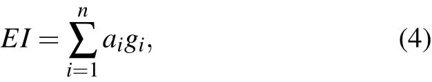
where gidenotes a set of linearly independent basis functions and aiis the weight coefficient. Combining Eqs.(1),(3),and(4),the final elastic equation of the feather in the matrix form can be obtained as

where KLand KNLare linear and nonlinear parts of the stiffness matrix,respectively.
To solve the structural stiffness distribution, another numerical flexibility test is conducted on the feather with the finite element method(FEM),which is similar to the proposed measuring method discussed in Section 2. During the test,the feather is subjected to the applied load and deformed. Considering that the shaft structure is quite complex,a huge number of elements are needed to accurately simulate the dynamic behavior of the feather,and the feather deformation of the eagle will be larger. We load the applied forces on the single-beam model with the selected flexibility distribution giand calculate the corresponding deflection distribution u.With the measured deflection,the coefficients aiin Eq.(4)are solved by an optimal method. The bending stiffness distribution EI can then be calculated from Eq.(4),and the deflection can be obtained by solving the nonlinear Eq. (5) about the variables u. Once the structural stiffness is obtained,the flexibility matrix can be extracted.
3.2. Optimal approach to estimate the coefficients
A minimal function is constructed to figure out the coefficients aiin Eq.(4)

where diis the calculated displacement using the FEM method, riis the measured displacement, and the subscript i denotes the ith marker point. The numerical formula for Eq.(6)is[44]

where xkis the defined current point, dkis the corresponding search direction, and αkis the step length. Let G(x) denote the gradient of F(x) at point xk. Deng et al.[45]proposed a derivative-free line search using the approximate norm descent condition
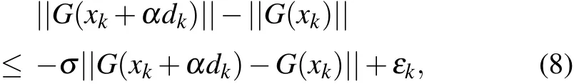
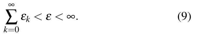
where σ ∈(0,1)and{εk}is a positive sequence satisfying the following inequality for some constant ε >0:
In the previous equations,α is found by backtracking,and the right side of Eq.(5)goes to a positive constant while the left side goes to zero.Thus,the iteration is well defined and a large step size of α can be obtained in the backtracking.
The updating formula of estimation for Jacobian matrix is always used. However, to reduce the computing costs, especially for a large number of equations,estimation of the inverse of Jacobian matrix will be an alternative way.[46]Let Bkbe the inverse matrix of the Hessian approximation matrix,the quasi-Newton method then solves the steepest descent dkof Eq.(6)with the following equation:

An updating formula of inverse of Jacobian matrix is
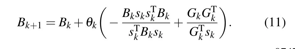
By combining objective function in Eq.(6)with the derivativefree line search method in Eq. (8) based on the approximate norm descent condition,[45]an optimized method of estimating stiffness distribution with a global convergence is obtained.[47]With the minimal function,the optimal problem of the stiffness distributions will be transferred to a problem of nonlinear equations. A numerical scheme of the optimal function in Eq.(6)is obtained,then the inverse Broyden-Fletcher-Goldfarb-Shanno(BFGS)method of Jacobean-free is used to solve Eq.(6).
Coupling the BFGS method with the FEM method, the nonlinear distribution is calculated by the FEM method. The displacement distribution is obtained to calculate the residue of the minimal function. Then,its approximate norm descent is estimated and the estimated EI is obtained by the BFGS method. The FEM and BFGS coupled algorithm can be obtained by repeating the previous iterations to optimize the stiffness distribution,as shown in Fig.2 and the following steps.
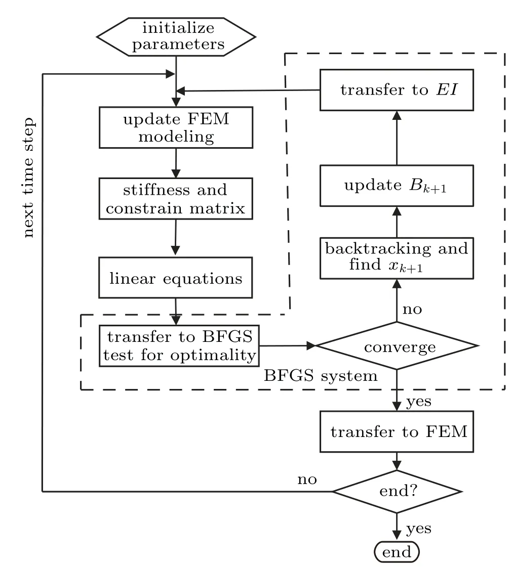
Fig. 2. An optimization method with FEM and BFGS coupled algorithm.
Step 0: initialization. The FEM model is built and the initial q0is set. Set default value of the algorithm: σ =0.5,γφ=0.5,ρ =0.2,εk=0.5/k2,η =0.8,and δ =10-10. Set B0as the identity matrix.Initialize feather geometry according to the shaft shape in the FEM modeling. The initial stiffness coefficients are set as 0.5.
Step 1:calculate displacement distribution using the FEM method. Update EI distributions using optimized results calculated by BFGS method. Calculate stiffness matrix and the nonlinear equations. Transfer the displacement of the shaft to the optimization function.
Step 2: BFGS system. Transfer freedom of FEM system to nonlinear equations and update the independent variables of nonlinear equations which are composed of stiffness coefficients. The BFGS method is used to solve the nonlinear equations until a convergence is obtained during each backtracking.
Step 3: solve the nonlinear equations,transfer solution of nonlinear equations to FEM modeling. If the end is achieved,then the results will be output,otherwise go to step 1 and calculate for the next iteration.
4. Results and discussion
The flexibility test is conducted on the feather shaft with the approach discussed in Section 2. The x-coordinate denotes the shaft position normalized by the shaft length, the y-coordinate denotes the applied force (normalized as a unit force)station,and the z-coordinate denotes the displacements of the feather shaft. F1to F8denote the forces applied at marker points 20%, 30%, 40%, 50%, 60%, 70%, 80%, and 90% stations, respectively, and the corresponding cases are denoted as cases (a)-(h). In each case, the feather is bent by thrusting the corresponding marker point (force station), and after a stable situation is achieved, eight displacements at all the shaft stations are measured simultaneously. Consequently,the flexibility of the shaft is presented with a three-dimensional(3D)surface,as shown in Fig.3. It is shown that larger deformations of the shaft are observed when the thrusting station moves from 0.1 to 0.9. The maximum deformations always appear at the feather tip of all the cases,whereas the extreme one is obtained as 7.84 mm when the thrusting station is applied at the 0.9 station. Meanwhile, the 0.0 station keeps undeformed for the calamus is clumped by the drill chuck, as shown in Fig.1.
Six functions illustrated in Fig. 4 are chosen as the basis functions for the bending stiffness distributions, including one constant function and five polynomial functions: f(x)=(1-x)k,k=0,1,2,3,4,5. In Fig.4,the x-coordinate denotes the shaft position normalized by the shaft length.
After the structural stiffness distribution is obtained, the flexibility matrix is extracted and the displacement at each station is obtained. The FEM calculations are implemented at each iteration. The experimental deflections are compared with the computed deflections as shown in Fig.5. It is shown that the maximum displacement appears at the feather tip in each test.As the location of force application gradually moves far away from the shaft root,more large displacements are observed,ranging from 0.13 mm to 7.84 mm.

Fig.3. The deformations of the shaft due to the force applied at stations in the range of 0.1 to 0.9.
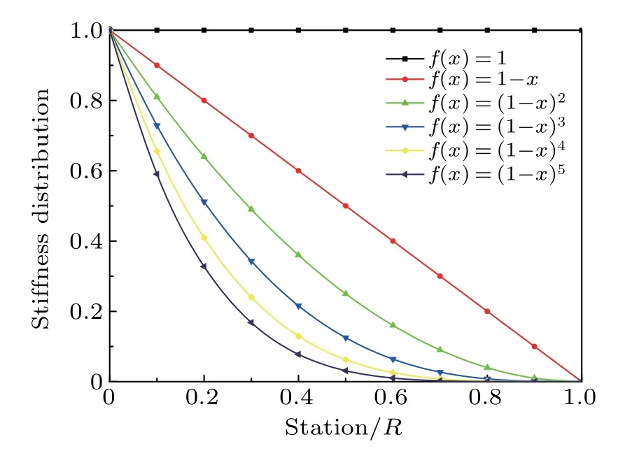
Fig.4. Basis functions of stiffness distribution.
In the numerical experiment, a polynomial-like curve is predicted before the force location. An exact linear distribution is found after the location. For instance, the force location is at the 20%station of the shaft in case(a),as shown in Fig. 5(a). The FEM model is bent before 20% station after the force application, while it keeps undeformed after the location. Consequently, a polynomial-like distribution appears before 20%station,and a linear distribution is found after the 20% station. The maximum deviation of each case increases as the applied force keeps far away from the root (from case(a) to case (h)). A maximum deviation of the predicted deformation and the experimental one is observed as 0.03 mm at the 60% station in case (a), while a maximum deviation is observed as 1.79 mm at the 90%station in case(h). Above all,the deflection distributions agree well with the experimental data in all the cases,which demonstrates the effectiveness and accuracy of the present method.
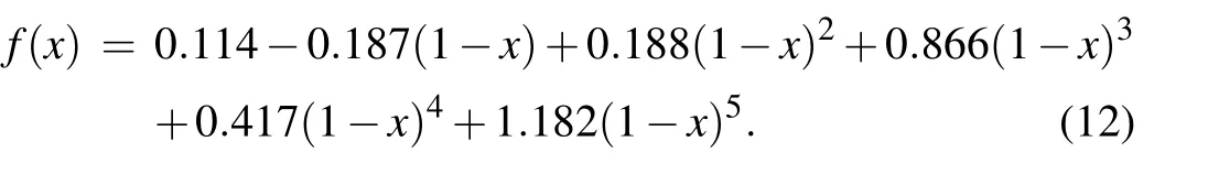
Finally,an optimized stiffness distribution is obtained as Figure 6 displays the optimized stiffness distribution, where large stiffness is found near the shaft root while more flexibility is obtained at the tip. With the proposed stiffness distribution,the structure model of a feather can be easily modeled to study the aeroelasticity,flight efficiency,etc.
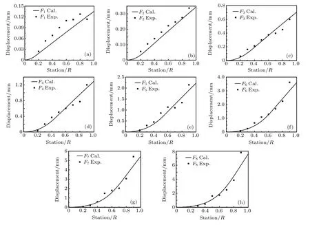
Fig.5. Comparison of computational deformation with the experimental one: panels(a)-(h)denote the cases(a)-(h).
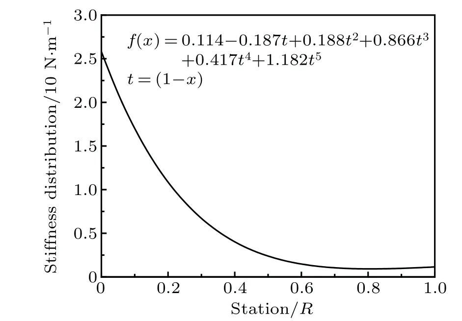
Fig.6. Bending stiffness distribution.
5. Conclusion
In this study, a feather stiffness evaluation method is developed and the stiffness distribution of the feather is investigated. The insights obtained from the study will be an inspiration for stiffness evaluation without material tests or geometry reconstruction of feathers. The following significant enhancements of our understanding are accomplished.
(I)In this work,the flexibility matrix of a primary feather of a golden eagle is tested by an in situ device. By simplifying the feather structure into a single-beam model,the bending stiffness distribution has been derived from the measured deformation.
(II) A BFGS-based optimal method has been developed to evaluate the stiffness of a bird’s feather. Good agreement with the experimental data have been achieved,and a bending stiffness distribution with 5th order is obtained. The proposed method has a high potential for the bending stiffness analysis of a bird’s feather.
Acknowledgments
The authors would like to thank the referees for their good and valuable suggestions which improved this paper greatly;thank the team of Zhongyong Fan for all their contributions on the specimen and the 3D scanning.
猜你喜欢
新作文·小学低年级版(2022年5期)2022-08-30
Chinese Physics B(2022年6期)2022-06-29
Chinese Physics B(2022年4期)2022-04-12
东坡赤壁诗词(2020年4期)2020-09-02
小猕猴学习画刊·下半月(2018年3期)2018-05-14
现代营销·经营版(2017年10期)2017-10-27
家庭影院技术(2017年8期)2017-10-13
晚晴(2017年6期)2017-06-27
商情(2017年5期)2017-03-30
今古传奇·故事版(2017年4期)2017-03-24

- Chinese Physics B的其它文章
- Coercivity mechanisms in nanostructured permanent magnets∗
- Progress in recycling of Nd-Fe-B sintered magnet wastes∗
- Grain boundary restructuring and La/Ce/Y application in Nd-Fe-B magnets∗
- Topology of triple-point metals∗
- Local evolutions of nodal points in two-dimensional systems with chiral symmetry∗
- Structural,elastic,and electronic properties of topological semimetal WC-type MX family by first-principles calculation∗