
Plasma characteristics and broadband electromagnetic wave absorption in argon and helium capacitively coupled plasma∗
2021-09-28 02:18WenChongOuyang欧阳文冲QiLiu刘琦TaoJin金涛andZhengWeiWu吴征威
Chinese Physics B 2021年9期
Wen-Chong Ouyang(欧阳文冲),Qi Liu(刘琦),Tao Jin(金涛),and Zheng-Wei Wu(吴征威)
School of Nuclear Science and Technology,University of Science and Technology of China,Hefei 230026,China
Keywords:capacitively coupled plasma,electron number density,absorption frequency,plasma stealth
1.Introduction
In recent years,the interaction between electromagnetic wave and plasma has received wide attention,for it has important applications in military,aeronautics,and industry,specifically,in plasma stealth,[1,2]communication blackout during atmospheric reentry,[3,4]and plasma diagnosis.[5,6]etc.The methods of computing the interaction of electromagnetic wave and plasma was developed by many researchers.[7–10]Zhang et al.numerically analyzed the reflection and absorption characteristics of electromagnetic waves propagating in a multilayer plasma plate by the wave impedance matching method.[11]Chen et al.studied the scattering characteristics of time-varying plasma at different incident angles and frequency bands by using the finite-difference time-difference(FDTD)method.[12]Guo L J and Guo L X theoretically solved the absorption coefficient of electromagnetic wave in a moving non-uniform plasma plate based on the covariance of Maxwell equations and the phase invariance of plane wave.[13]
With the application of plasma to the discharge devices,many researchers pay attention to the propagation characteristics of electromagnetic waves in inductively coupled plasma(ICP)[14,15]and capacitively coupled plasma.[16,17]Li et al.used the improved scattering matrix method(SMM)to study the influence of collision frequency and incident angle on resonance absorption based on the plasma distribution of typical inductively coupled plasma discharge.[18]Wei et al.investigated the influence of the power and atmospheric pressure parameters of ICP discharge on the attenuation of 4 GHz–5 GHz electromagnetic waves.[19]Zhang et al.studied the changes of electromagnetic wave transmission attenuation with the pressure and applied voltage parameters of CCP discharge,and discussed the applications of helium CCP in absorbing electromagnetic waves.[20]However,the parameters that affect the attenuation of electromagnetic wave are not only the pressure but also power.According to our previous research,[4]the electron number density and collision frequency are the main factors that affect the attenuation of electromagnetic waves.The difference in discharge gas,power frequency,discharge gap,and other parameters will also change plasma parameters(electron number density and collision frequency)and affect the attenuation of electromagnetic wave.Therefore,it is necessary to study the characteristics of CCP plasma discharge under these conditions and further analyze their influence on the electromagnetic wave propagation for plasma stealth applications.
In this paper,a self-consistent calculation model for CCP discharge and electromagnetic wave propagation is developed.Then the influence of difference in discharge gas,discharge gap,power frequency,pressure,and power on the plasma distribution and transmission attenuation are analyzed.Finally,the corresponding parameters of the best electromagnetic wave absorption effect and the applications in plasma stealth are discussed.
2.Description of model
2.1.CCP discharge model
2.1.1.Equation of fluid model
The CCP is a classical plasma discharge device used to study plasma diagnosis and electromagnetic wave propagation characteristics.The numerical simulation methods of CCP mainly include particle-in-cell(PIC)model,[21]fluid model[20]and global model.Compared with the other two methods,the fluid model is widely used due to the fast calculation speed and better description of the plasma process.
In this paper,a one-dimensional drift diffusion fluid model is used to investigate the CCP discharge characteristics under different conditions(such as the discharge gas,RF power,etc.).The electron density and electron energy density are obtained by solving the drift diffusion equation
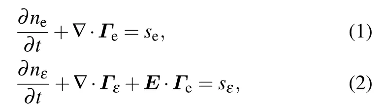
where neis the electron density,nεis the electron energy density,E is the electric field,seand sεrepresent the electron source term and the electron energy source term produced,respectively,by inelastic collision and elastic collision between electrons and neutral particles,etc.,ΓeandΓεare respectively solved according to
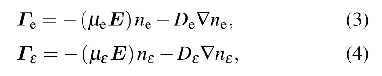
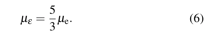
whereµeandµεrepresent the mobility coefficient of electron and electron energy,respectively.According to the Surendra’s conclusion,[22]the electron mobility coefficient and neutral density satisfy the following relationship:

The mobility coefficient of electron energy is calculated from
The diffusion coefficients is defined as
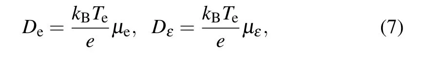
where Deand Dεrepresent the diffusion coefficient of electron and electron energy,respectively,kBis the Boltzmann constant,Teis the electron temperature.
The terms seand sεare obtained from the following equations,respectively:
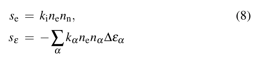

where kiis the ionization coefficient,nαis the density of species a,Δεαis the energy loss rate coefficient,meis the electron mass,mαis the mass of heavy species a,Tgis the gas temperature,and ve,nrepresents the electron–neutral momentum transfer collision frequency.
The electron temperature and the average electron energy have the following relationship:

where nε/nerepresents the average electron energy.
For ions and other neutral particles,they are expressed by solving the average diffusion model of the mixture[23,24]

whereρis the density of mixed species,wais the mass fraction of species a,u is the average velocity of all species(can be regarded as fluid),jarepresents the mass flux of species a,and Rais the source term related to the reaction rate of species a.
The density of mixed species and mass flux of species are calculated from the following equations,respectively:

where Mnis the average molar mass,pAis the absolute pressure,R is the gas constant,T is the gas temperature,and vais the velocity of species a.
The velocity of the species a is obtained by solving the following equation:


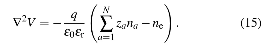
The electric field is calculated from the Poisson equation
2.1.2.Discharge parameters
The structure of the CCP discharge device is shown in Fig.1.It consists of two electrodes with 30 cm in length,the two electrodes are parallel and have a certain interspace.The upper electrode and the lower electrode are externally connected by an RF power supply,and the lower electrode is grounded.

Fig.1.Schematic diagram of CCP discharge device.
In order to study the influence of different discharge parameters on plasma discharge characteristics and electromagnetic wave propagation characteristics,the discharge gap,RF power,RF frequency and pressure in the cavity are set to be 5 cm–15 cm,50 W–300 W,13.56 MHz–45 MHz and 0.1 Torr–0.5 Torr(1 Torr=1.33322×10²Pa)in this paper,respectively.The specific conditions of each discharge parameter are shown in Table 1.

Table 1.Specific values of discharge parameters.
2.1.3.Chemical reaction of gas discharge
In this model,the argon and helium are considered as discharge gas.Four species and seven chemical reactions are taken into account in the argon discharge model as shown in Table 2.The four species are Ar(argon atom),Ar∗(argon metastable atom),Ar+(argon ion),and e(electron),respectively.
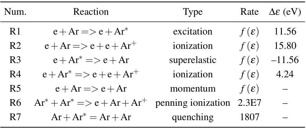
Table 2.Chemical reactions in argon plasma discharge model.

Table 3.Chemical reaction in helium plasma discharge model.
For the helium plasma discharge model,four species including He(helium atom),He∗(helium metastable atom),He+(helium ion),and e(electron)are considered in the chemical reactions.The specific chemical reactions for yielding the four species are shown in Table 3.The reaction coefficient indicated by f(ε)in argon and helium plasma discharge model are computed by cross-section data and BOLSIG+.
2.1.4.Boundary conditions
The heat emission flux is approximately ignored in this paper,and the boundary conditions of electron and electron energy flux on the wall in the CCP discharge model are respectively expressed by
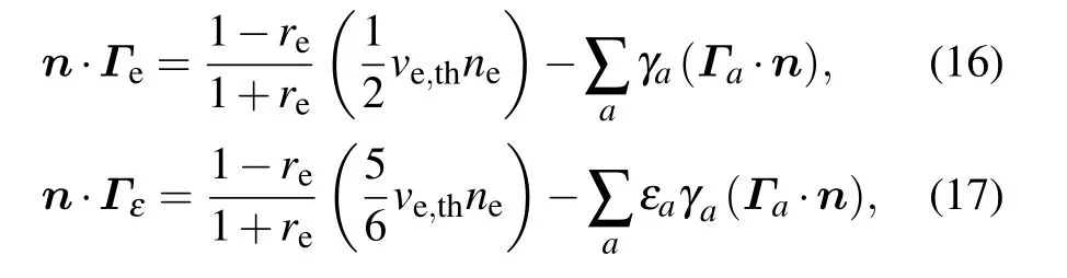
where n represents the normal pointing towards the wall,reis the reflection coefficient,ve,this the thermal velocity of a single electron,andγais the secondary electron emission coefficient.
In addition,the initial temperature in the discharge cavity is set to be 300 K,the reflection coefficient of the wall boundary is zero,the initial electron number density is 1014m−3,and the initial average electron energy is 4 eV.The input power is expressed as

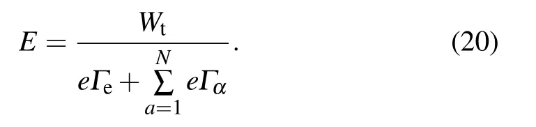
The total time-average power density satisfies the following relationship:

where Wtis the total time-average power density and S is the parallel plate electrode areas.According to Eq.(18),the electric field can be solved by the total power density[20]
The corresponding electric potential and current density are obtained according to the following equations:[20]

where V is the electric potential,J is the current density,and Γαis the flux of species a.
2.2.Electromagnetic wave propagation model
Since the one-dimensional CCP discharge model in this paper simulates the characteristics of plasma discharge from anode to cathode,the multilayer transmission model[25]is used to calculate the propagation characteristics of electromagnetic waves in plasma generated by CCP discharge.The plasma between the anode and the cathode can be divided into l homogeneous layers,and electromagnetic waves propagate through the plasma in the y-axis direction.
The electromagnetic wave propagation coefficient of the l layer is solved according to the following equation:
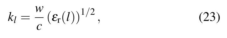
where w is the angular frequency of electromagnetic wave,c is the speed of light,εr(l)is the relative dielectric constant of plasma in the l-th layer.
The electric field of the l-th layer is expressed as
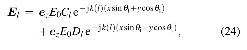
where Clis the reflection coefficient,Dlis the transmission coefficient,and E is the electric field.
Since the electric field and magnetic field on the propagation boundary meet the continuity of the tangential component and phase matching,the relationship between reflection coefficient and transmission coefficient can be expressed in the matrix form as follows:

where Smis expressed as

By substituting the boundary conditions into Eq.(25),the following relationship is obtained

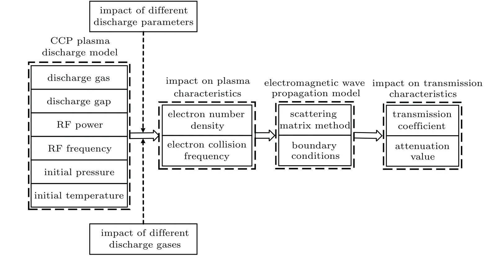
Fig.2.Algorithm flowchart of self-consistent calculation model for CCP discharge and electromagnetic wave propagation.
where A is the total reflection coefficient,F is the total transmission coefficient,Sgis expressed in the matrix form,Vpis defined as follows:
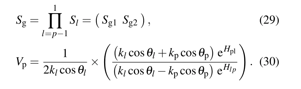
Finally,the total reflection coefficient and transmission coefficient are solved according to the following equation:

The attenuation of the electromagnetic wave through the CCP discharge plasma is obtained according to the transmission coefficient

where Att is the attenuation value.
Based on the CCP plasma discharge and electromagnetic wave propagation model,a one-dimensional self-consistent calculation model is proposed to investigate the propagation characteristics of electromagnetic waves in the plasma discharge device.The specific algorithm flow can be divided into two steps as shown in Fig.2.The first step is to use the CCP discharge model established by COMSOL multiphysics to study the effect of the difference in discharge gas,discharge gap,RF power,RF frequency,and pressure on the characteristics of the generated plasma.The second step is to take the electron number density and collision frequency of the plasma as inputs into the electromagnetic wave transmission model established by MATLAB code,and the influence of difference in discharge parameter and the discharge gas on the electromagnetic wave attenuation are obtained.
3.Simulation results and discussion
3.1.Plasma characteristics under different discharge gases and parameters
In the process of numerical solution of CCP discharge model,a large number of RF cycles(102–105)are needed to obtain a steady-state solution.In order to speed up the calculation efficiency,the COMSOL plasma module introduces periodic boundary conditions to quickly calculate the stable state.Taking the metastable particles in the CCP discharge for example,the evolution of the particles is described by using Eq.(33),and the periodic boundary conditions are shown in Eq.(34);

where n is the number of metastable particles.The first term on the right-hand side in Eq.(33)represents the periodic generation of metastable states and periodic oscillation in the plasma sheath.The second term refers to the loss caused by the collision with the background gas,and the third term is the loss caused by the collision between metastable particles.
In order to verify the accuracy of the CCP discharge model,figure 3 shows the comparison of electron number density between CCP discharges of argon and helium,for measurement results and simulation results obtained from the present study and other researchers.[20,26]It can be seen from Fig.3(a)that the electron number density distribution of helium discharge in this paper is in good agreement with the simulation results given by Zhang et al.[20]The electron number density distribution in the argon discharge in this paper accords well with the simulation results and experimental results reported by Pan et al.[26]However,the electron number density distribution near the electrode is quite different,because the edge effect is not considered in Ref.[26].
Figure 4 shows the electron density distribution of argon discharge and helium discharge at gas pressure p=0.5 Torr,discharge gap L=0.1 m,RF power P=300 W,and RF frequency f=13.56 MHz.It is obvious that the electron number density under argon discharge is higher than that under helium discharge.And the maximum electron number density differs by more than 10 times,which is consistent with the conclusion drawn under the inductively coupled plasma(ICP)discharge mode.[27]In addition,although the electron number density of helium is lower than that of argon,the uniform range of plasma in the central region is larger than the case of argon discharge.The reason is that the degree of ionization of argon gas is higher than that of helium gas.It is also verified from the side that the electron number density and uniformity are often mutually restricted.
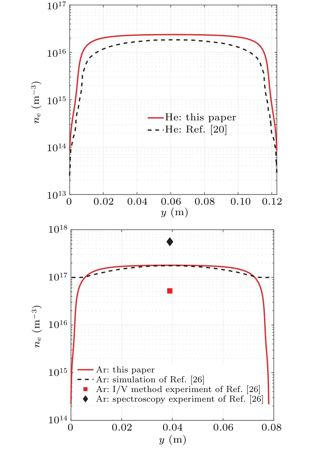
Fig.3.Comparison of electron number density distribution between argon and helium CCP discharges,for measurement results and simulation results obtained from the present research and other researches,showing(a)helium discharge at gas pressure p=0.5 Torr,discharge gap L=0.123 m,parallel plate length l=0.28 m,input voltage V=1000 V,and RF frequency f=13.56 MHz,and(b)argon discharge at gas pressure p=250 Pa,discharge gap L=0.078 m,parallel plate length l=0.1 m,RF power P=100 W,and RF frequency f=13.56 MHz.

Fig.4.Electron number density distribution of argon discharge and helium discharge at gas pressure p=0.5 Torr,discharge gap L=0.1 m,RF power P=300 W,and RF frequency f=13.56 MHz.
The electron number density distributions of argon discharge under different gas pressures are shown in Fig.5.It can be concluded that the electron number density increases with gas pressure increasing.The maximum electron density corresponding to gas pressure p=0.1 Torr,0.3 Torr,and 0.5 Torr is 4.71×10¹⁶m−3,1.59×1017m−3,and 2.09×10¹⁷m−3,respectively.The increase in gas pressure will intensify the collisions between different particles,leading the electron number density to increase.
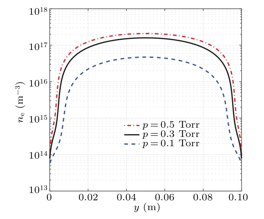
Fig.5.Electron number density distributions of argon under different gas pressures at discharge gap L=0.1 m,RF power P=300 W,and RF frequency f=13.56 MHz.
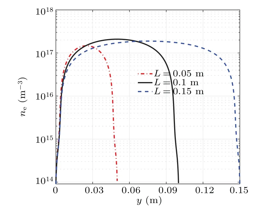
Fig.6.Electron number density distributions of argon discharge under different discharge gaps at gas pressure p=0.5 Torr,RF power P=300 W,and RF frequency f=13.56 MHz.
Figure 6 shows the electron number density distributions under different discharge gaps.It is obvious that the electron number density first increases and then decreases with discharge gap increasing,and the maximum appears in the case L=0.1 m.The results show that the maximum electron densities are 6.81×10¹⁶m−3,2.09×1017m−3,and 1.88×10¹⁷m−3,corresponding to the discharge gap of 0.05 m,0.1 m,and 0.15 m,respectively.As the discharge gap decreases exponentially,the uniform range of the plasma density in the central area decreases more than the discharge gap does.Figures 7 and 8 respectively show the electron number density distribution under different values of RF power and RF frequency.It can be seen from Figs.7 and 8 that the electron number density increases with the augment of RF power and frequency.The increase of the input power will make the electrons gain more energies in the electrode sheath,and more high-energy particles will collide with the background gas in the cavity to generate more electrons.The increase of the RF frequency will cause the RF frequency and the oscillation frequency of the electrons to increase,thereby increasing the collision between the electrons and the particles in the background gas.On the other hand,the induced component,as a factor that affects the electron number density,also increases with RF frequency rising.[28]In addition,the influence of RF power on the electron number density is greater than that of RF frequency.
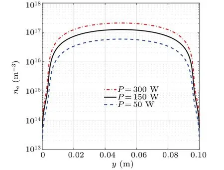
Fig.7.Electron number density distributions of argon discharge under different values of RF power at gas pressure p=0.5 Torr,discharge gap L=0.1 m,and RF frequency f=13.56 MHz.

Fig.8.Electron number density distributions of argon discharge under different RF frequencies at gas pressure p=0.5 Torr,discharge gap L=0.1 m,and RF frequency f=13.56 MHz.
3.2.Electromagnetic wave attenuation for different discharge gases and parameters
The self-consistent simulation model of CCP discharge and electromagnetic wave is based on the electron number density and collision frequency data in CCP discharge to study the attenuation of electromagnetic wave propagation in plasma.The electron collision frequency can be estimated by the following equation:[29]
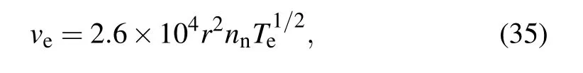
where veis the electron collision frequency,r is the sum of electron–neutral collisional radius(According to Refs.[30]and[31]the average cross section of helium satisfiesπr2=7.63×10⁻²⁰m2,the average cross section of argon follows πr2=2.32×10⁻¹⁹m2).According to the simulation results in this paper,the periodic average values of the electron temperatures of helium and argon are about 5 eV and 10 eV(1 eV=11300 K),respectively.Combining Zhang’s estimation[20]of the electron collision frequency under CCP discharge,the final formulas for collision frequency of helium and argon are obtained,respectively,
where veand p are measured in units GHz and Torr,respectively.
3.3.Transmission attenuation of different discharge gases
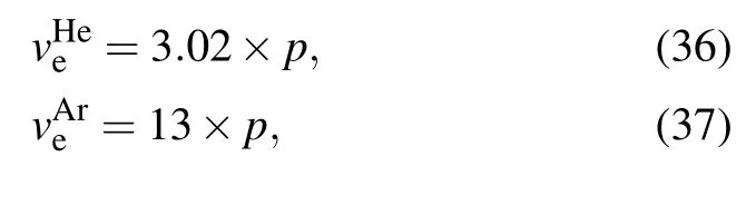
Figure 9 shows the transmission attenuation in argon discharge plasma and helium discharge plasma at the same discharge parameters.It is obvious that the attenuation of electromagnetic wave in argon discharge is greater than that in helium discharge.The reason is that although the electron collision frequency of argon discharge is higher than that of helium discharge,the electron number density of argon discharge is much higher than that of helium discharge.It is generally believed that the normal communication cannot be achieved if the signal attenuation exceeds−5 dB.The plasma produced by helium discharge has little absorption of electromagnetic wave energy and weaker interference to signal communication.The plasma produced by argon discharge has significant absorption of electromagnetic wave energy in a frequency range from 0.01 GHz to 10 GHz,and the absorption peak reaches−13 dB at 2.41 GHz.Therefore,the plasma generated by argon discharge is more suitable for the research of plasma stealth applications.
Fig.9.Plots of transmission attenuation of electromagnetic wave in argon discharge and helium discharge.
In addition,it can be seen from Fig.9 that the transmission attenuation curve under argon discharge can be divided into two parts.The electromagnetic wave frequency range of part 1 is 0.01 GHz–2.41 GHz,and the transmission attenuation decreases significantly with frequency increasing.At this time,the wavelength is greater than the thickness of the plasma layer,the diffraction effect is dominant,and the penetration effect is not obvious.The electromagnetic wave frequency of part 2 is greater than 2.41 GHz,and the transmission attenuation increases significantly with the frequency increasing.The corresponding wavelength is close to and slowly far below the thickness of the plasma layer.At this time,the penetration effect is dominant and the diffraction effect can be ignored.
3.4.Transmission attenuation of different discharge parameters
Figure 10 shows the attenuation of electromagnetic waves in plasma generated by argon discharge at different pressures.The transmission attenuation decreases with the increase of pressure,because the increase in pressure causes the electron density in the discharge plasma to increase.However,this trend will not always be maintained.It can be seen from Fig.10 that the maximum transmission attenuation under a pressure of 0.3 Torr is higher than 0.5 Torr.The reason is that the increase in pressure leads the mean free path of electrons to decrease,which increases the frequency of electron collisions.At this time,the influence of electron collision frequency is higher than that of the change of electron number density.Therefore,the gas pressure needs to be carefully selected according to actual influence.

Fig.10.Plots of transmission attenuation of electromagnetic waves in argon discharges at different gas pressures.
As the discharge gap increases,the thickness of the plasma sheath increases,while the electron number density first increases and then decreases.Therefore,the transmission attenuation of electromagnetic waves does not change monotonically with the discharge gap increasing.Figure 11 shows the transmission attenuation in plasma generated by different discharge gaps.The peaks of transmission attenuation are−3.8 dB,−12.9 dB,and−12.8 dB,corresponding to the discharge gaps of 0.05 m,0.1 m,and 0.15 m,respectively.The transmission attenuation of electromagnetic waves first increases and then decreases with the discharge gap inceasing,and the attenuation reaches a maximum value at L=0.1 m.The transmission attenuation is within−5 dB when the discharge gap is 0.05 m,which shows that the plasma generated at this time has little interference to the signal.

Fig.11.Plots of transmission attenuation of electromagnetic waves in argon discharges of different discharge gaps.
Figures 12 and 13 respectively illustrate the transmission attenuation of plasma generated by different values of RF power and RF frequency.It is obvious that the transmission attenuation of electromagnetic waves increases with the augment of RF power and RF frequency.The reason is that the increase of RF power and RF frequency have no effect on the electron collision frequency,but it will increase the electron number density.
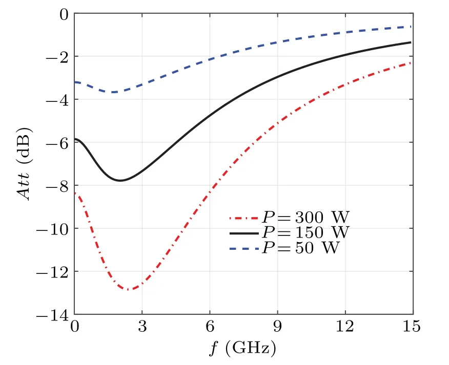
Fig.12.Plots of transmission attenuation of electromagnetic waves in argon discharges of different values of RF power.
One can observe that higher RF power and RF frequency have a wider strong absorption frequency band for electromagnetic waves.The peaks of transmission attenuation are−3.7 dB,−7.8 dB,and−12.9 dB,corresponding to the RF power of 50 W,150 W,and 300 W,respectively.The plasma generated at power of 50 W has almost no interference to electromagnetic wave transmission in any frequency band.But when the power is increased to 300 W,the wave frequency range that can be absorbed is 0.01 GHZ–9.1 GHz,which includes L-band,S-band,and C-band.When the RF frequency increases from 13.56 MHz to 45 MHz,the transmission attenuation increases from−12.9 dB to−22.5 dB.Meanwhile,the maximum frequency of electromagnetic wave absorption ranges from 9.1 GHz to 13.7 GHz,and the frequency band for electromagnetic wave absorption expands from C-band to X-band,and even Ku-band.
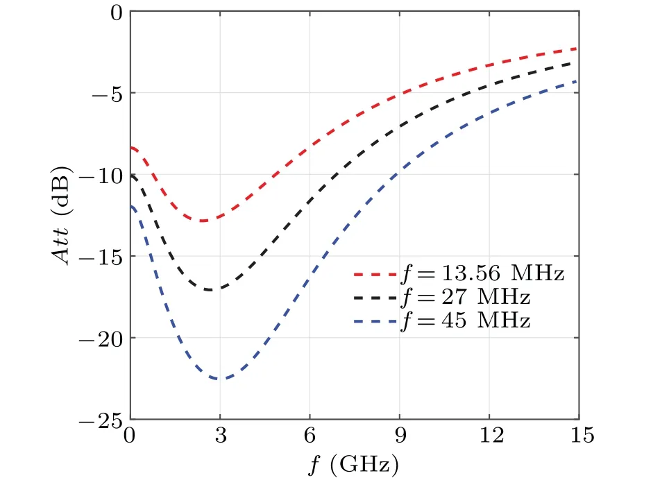
Fig.13.Plots of transmission attenuation of electromagnetic waves in argon discharges of different RF frequencies.
4.Conclusions and perspectives
Based on the CCP discharge method,the effects of different gases and discharge parameters on the electron number density and transmission attenuation are studied in this paper.A large amount of helium and argon plasma are generated between two 30-cm-long parallel rectangular plates where gas pressure is p=0.1 Torr–0.5 Torr,discharge gap is L=0.025 m–0.1 m,RF power is P=50 W–300 W,RF frequency is f=13.56 MHz–45 MHz.The CCP discharge characteristics and electromagnetic wave transmission attenuation under different discharge gases and parameters are obtained by a self-consistent calculation model combining the drift diffusion fluid model and the improved scattering matrix method.Conclusions are summarized below.
(i)The electron number density increases with the augment of gas pressure,RF power,and RF frequency,while it first increases and then decreases with the increase of discharge gap.In addition,the electron density of argon plasma discharge is much higher than that of helium plasma discharge.
(ii)The absorption effect of argon discharge plasma on electromagnetic waves is much greater than that of helium discharge plasma,so it will be prioritized as the discharge gas for plasma stealth.Meanwhile,transmission attenuation increases with the augment of RF power and RF frequency.So the RF power and RF frequency should be increased as much as possible without affecting the normal discharge of CCP.However,the choice of gas pressure and discharge gap should be considered based on the actual situation,because the transmission attenuation does not increase or decrease monotonically with the increase of pressure and discharge gap.
(iii)The maximum transmission attenuation of CCP discharge plasma to electromagnetic waves under the best parameters in this paper is−22.5 dB.The maximum frequency of electromagnetic wave absorption is 13.7 GHz,and the corresponding absorption electromagnetic wave band ranges from S band to Ku band.
The discharge characteristics of CCP and the corresponding transmission attenuation are of great significance in plasma stealth applications.The experimental platform of microwave chamber for CCP discharge and electromagnetic wave propagation is currently being built.And the two-dimensional and three-dimensional self-consistent models combining CCP discharge and electromagnetic wave propagation will be studied in our future work.
猜你喜欢
———记中船黄埔文冲船舶有限公司
中国修船(2022年2期)2022-04-28
High Technology Letters(2021年4期)2022-01-09
故事作文·低年级(2021年2期)2021-02-04
故事作文·低年级(2021年2期)2021-02-04
——记广州文冲船舶修造有限公司
中国修船(2020年6期)2021-01-06
作文大王·低年级(2020年12期)2020-12-31
——记中船黄埔文冲船舶有限公司
中国修船(2020年5期)2020-10-26
中华诗词(2019年9期)2019-05-21
黑龙江交通科技(2017年6期)2017-08-28
美与时代·城市版(2016年9期)2016-05-14
- Chinese Physics B的其它文章
- Multiple solutions and hysteresis in the flows driven by surface with antisymmetric velocity profile∗
- Magnetization relaxation of uniaxial anisotropic ferromagnetic particles with linear reaction dynamics driven by DC/AC magnetic field∗
- Influences of spin–orbit interaction on quantum speed limit and entanglement of spin qubits in coupled quantum dots
- Quantum multicast schemes of different quantum states via non-maximally entangled channels with multiparty involvement∗
- Magnetic and electronic properties of two-dimensional metal-organic frameworks TM3(C2NH)12*
- Preparation of a two-state mixture of ultracold fermionic atoms with balanced population subject to the unstable magnetic field∗