
On the deformation behavior of heterogeneous microstructure and its effect on the mechanical properties of die cast AZ91D magnesium alloy
2022-09-26 03:09MengwuWuYingyingHouLinHuHuijunXiooLiShoumeiXiong
Journal of Magnesium and Alloys 2022年7期
Mengwu Wu,Yingying Hou,Lin Hu,Huijun M,*,Xioo Li,Shoumei Xiong
aHubei Key Laboratory ofAdvanced Technologyfor Automotive Components,Wuhan University of Technology,Wuhan 430070,China
b School ofMaterialsScience and Engineering,Tsinghua University,Beijing 100084,China
Abstract Both a conventional flow distributer and an improved one with a flow buffer were applied respectively during the high pressure die casting(HPDC)process,and samples of AZ91D magnesium alloy with different microstructure mainly consisting of α-Mg grains,β-phase and porosities were obtained.According to the grain orientation analysis,the predominant deformation behavior in α-Mg grains was dislocation slip,supplemented by deformation twinning.Dislocation slip was more difficult to occur in the samples with the improved flow distributer on account of the fact that the size of α-Mg grains in the microstructure was finer and more uniform.During the in situ tensile deformation test,cracks were observed to initiate from gas-shrinkage pore and island-shrinkage,and two main crack propagation mechanisms,porosity growth and coalescence were found accordingly.When the crack was in contact with the β-phase,it would pass through and fracture the network β-phase,whereas bypass the island β-phase by detaching it from the surrounding α-Mg grains.Mechanical property tests showed that the samples with relatively more homogeneous microstructure would perform higher mechanical properties,which was the combined effect of matrix α-Mg grains,β-phase,and porosities.
Keywords:Magnesium alloy;High pressure die casting;Microstructure;Deformation behavior;Mechanical properties.
1.Introduction
With the increasing demand for lightweight in the automotive,aerospace,electronics and other fields,magnesium alloys have received widespread attention with the advantages of low density,high specific strength,good machinability and recyclability,etc[1–3].Molten magnesium alloy has low viscosity,good fluidity,and it solidifies fast with good dimensional stability[4,5].The excellent castability makes it specifically suitable for high pressure die casting(HPDC)process,and in fact the HPDC process has already become the major forming process for magnesium alloys[6–8].
On the other hand,the large-scale application of magnesium alloy die castings as load-bearing parts still faces several challenges.This may be due to the shortcomings of magnesium alloys,such as relative low absolute strength and poor ductility at room temperature[9–11].Attributed to a hexagonal close-packed(HCP)crystal structure,the number of slip system for magnesium alloys is limited during plastic deformation.As the slip form can be summarized and classified into basal slip,prismatic slip and pyramidal slip,the critical resolved shear stress(CRSS)for non-basal slip is generally high,which results in a reality that non-basal slip is difficult to be activated[12–15].In this case,twin deformation is another important plastic deformation mechanism for magnesium alloys[16–18].
In addition to the inherent limitation induced by a HCP crystal structure during plastic deformation,the microstructure of die cast magnesium alloy also has a significant influence on the mechanical properties.The typical microstructure of die cast Mg-Al alloy generally consists ofα-Mg grains,β-phase and porosities.In-depth investigations have been conducted that theα-Mg matrix is composed of fine grains and coarse dendrites which are named ESCs(externally solidified crystals)[19–23].The porosities can be identified into four types,including gas pore,gas-shrinkage pore,net-shrinkage and island-shrinkage according to the formation mechanism and morphology characterization[24,25].A low Al content of the Mg-Al alloy and a high cooling rate during the HPDC process lead to a fully divorced eutectic morphology of theβ-phase at theα-Mg grain boundaries[26–28].Meanwhile,a band with porosity aggregation called the defect band is usually observed at the cross section of die castings[29–31].Extensive studies have been carried out on the correlation between the microstructure features mentioned above and their effects on the mechanical properties of die castings.For example,gas-shrinkage and net-shrinkage are inclined to form at the grain boundaries of coarse ESCs.The porosities would reduce the efficient force bearing area,thus exerting a deleterious effect on the strength and ductility of die castings[32,33].However,very few studies have been performed on the micro-deformation behavior ofα-Mg grains,β-phase and porosities,as well as their combined effect on the mechanical properties of magnesium alloy die castings.It is clear that understanding of such correlation could help researchers to give suggestions for controlling the microstructure formation of die cast magnesium alloy and improving the performance of die castings.
In this study,two types of die cast magnesium alloy samples were obtained with different flow distributers during the HPDC process.Microstructure characterization of the samples before and after tensile deformation was conducted by using OM,SEM,EBSD and X-ray tomography.Qualitative and quantitative analysis of the microstructure features,includingα-Mg grains,β-phase and porosities,as well as tensile tests were carried out,based on which the deformation behavior of these features and their effects on the mechanical properties of die castings were discussed.
2.Experimental
During the experiment,a specific casting(Fig.1(a))was produced using AZ91D magnesium alloy by a TOYO BD-350V5 cold chamber die casting machine with a vacuum system assisted.Both a conventional flow distributer and an improved one were applied during the HPDC process(Fig.1(b,c)),and the die cast samples were classified into two types,A and B,respectively.The improved flow distributer with a flow buffer was specially designed to prevent the ESCs from entering the die cavity[19].The key process parameters adopted during the HPDC process are listed in Table 1.All specimens were extracted from location T as shown in Fig.1(a).

Table 1Process parameters used during casting.

Table 2Quantitative characterization of the different microstructure features.
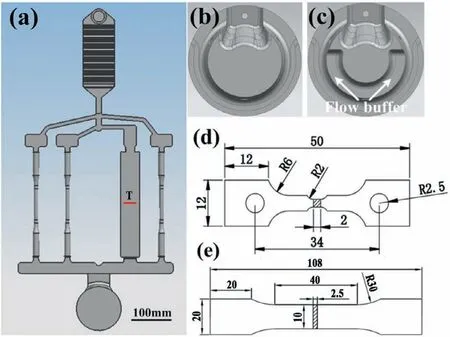
Fig.1.Configuration of(a)the specific casting including three tensile test bars and one plate sample,(b)conventional flow distributer,(c)improved flow distributer,(d)tensile specimen for in situ observation,and(e)tensile specimen for mechanical property tests.All the specimens were extracted from location T[19].
A ZEISS scope A1 optical microscope(OM)and a Hitachi S-4500 scanning electron microscope(SEM)were used for metallography observation,while the specimens were treated following the standard metallographic procedures and etched with a diluted acetic acid solution of 50 mL distilled water,150 mL anhydrous ethyl alcohol and 1 mL glacial acetic acid[34].The grain orientation information of the specimens was calibrated by electron back-scattered diffraction(EBSD)experiments performed with a ZEISS MERLIN Compact SEM with HKL Channel 5 system.The porosity distribution inside the specimens was scanned using the Phoenix vtome|xs(General Electric Company)equipment.The applied voltage and current in the tube were 110 kV and 100 μA,respectively.With an image resolution of 1.167 μm,the 3D morphology of the porosity was reconstructed using VGStudio Max 2.0 software.Microimage Analysis and Process System(MIAPS)was employed to perform a quantitative analysis of the microstructure features.
To analyze the deformation behavior of the microstructure features as well as the related crack initiation and propagation,in situobservation was conducted in the SEM chamber on the tensile specimens(Fig.1(d)),while a deformation speed of 0.1 mm/min was controlled during the tensile tests.Mechanical property tests were carried out by an electronic universal testing machine with a loading rate of 1 mm/min on the specimens as shown in Fig.1(e).Afterwards,the fracture surface of the specimens was furtherly examined by SEM and X-ray tomography to identify the crack initiation sites and fractography.
3.Results
3.1.As-cast microstructure
Fig.2 shows the typical microstructure of AZ91D magnesium alloy die cast samples.According to Fig.2(a)and(d),much less ESCs were observed in the microstructure of sample B casted with an improved flow distributer comparedwith that of sample A casted with a conventional flow distributer.In this case,the flow buffer designed in the improved flow distributer proved effective for preventing the ESCs from entering the die cavity,while earlier studies had demonstrated that the ESCs were initially formed in the melt whose superheat had already been lost due to the impingement on the relatively cold shot sleeve wall and plunger[21].In other words,the flow buffer acted as a ESCs collector during the melt filling stage of the HPDC process.It could be seen from Fig.2(b,c)and(e–f)that due to a considerable reduction of the number of coarse ESCs,the size ofα-Mg grains in the microstructure of sample B was finer and more uniform than that of sample A.Meanwhile,both networkβ-phase and islandβ-phase were observed in the microstructure of sample A and B,while more networkβ-phase with lager size was found at the grain boundary of coarse ESCs in sample A.

Fig.2.Typical microstructure of(a-c)sample A casted with a conventional flow distributer,and(d-f)sample B casted with an improved flow distributer.(a)and(d)observed by OM,while(b-c)and(e,f)observed by SEM.
The typical morphology and distribution of porosities in the microstructure of die cast samples obtained via X-ray tomography is shown in Fig.3.In the authors’previous work[24],the porosities in die castings were distinguished into gas pore,gas-shrinkage pore,net-shrinkage and island-shrinkage by the formation mechanism and morphology characterization.Since a vacuum system was employed during the HPDC process in this experiment,the number of gas pores was significantly reduced in the microstructure of both sample A and sample B.According to Fig.3(a–c)and 3(d–f),more gas-shrinkage pores with larger size were observed in the microstructure of sample A,while the porosities in sample B revealed a more dispersed and island-shrinkage morphology.
To further analyze the microstructure features in die cast samples quantitatively,three indicators,including diameter(d),roundness(R)and area/volume fraction(f)were used on behalf of the size,morphology and content of ESCs,β-phase and porosities,which were defined by the following Eqs.(1–6):[25]


Fig.3.Typical morphology and distribution of porosities in the microstructure of(a–c)sample A and(d–f)sample B.(a)and(d)2D slice images scanned by X-ray tomography,while(b,c)and(e-,f)3D images reconstructed by VGStudio Max 2.0 software.

whereA(ESCs,β)andAirepresent the actual area of ESCs orβ-phase.Pis the actual perimeter of ESCs orβ-phase.VporosityandVidenote the actual volume of porosities,whileSis the actual surface area of porosities.A0andV0are the total area and volume of the selected statistical zone,respectively.The specific values of these parameters were acquired by using the MIAPS software.Here,nin Eqs.(3)and(6)is the number of the targets(ESCs orβ-phase or porosities)counted.According to the definition of roundness(R)in Eqs.(2)and(5),a larger value of the roundness indicates that the morphology of the target is more complex.
Fig.4 and Table 2 show the statistical results relating the microstructure features in sample A/B.It could be illustrated that the average diameter and roundness of the ESCs in sample A were larger than those in sample B,as well as theβ-phase and porosities.In particular,the area/volume fraction of the ESCs/porosities in sample A was much larger than that in sample B,while the area fraction ofβ-phase was slightly larger in sample A.So far,the statistical results were consistent with the qualitative analysis on the microstructure of die cast samples as shown in Figs.2 and 3.
3.2.Deformation behavior
3.2.1.Deformation behavior of α-Mg grains
To analyze the deformation behavior of theα-Mg grains in die cast magnesium alloy,the grain orientation information of the specimens before and after tensile deformation was calibrated via EBSD as shown in Figs.5–9.It could be noted from Fig.6(a)and(c)that there was a small orientation difference inside theα-Mg grains.Hence,dislocation slip could be judged to occur in theα-Mg grains of sample A both under as-cast and deformed state[12].Explaining from the formation mechanism,the dislocation slip in theα-Mg grains of as-cast sample A may be caused by the casting pressure during the filling and solidification stages of magnesium alloy,while the slip was mainly caused by the tensile stress in theα-Mg grains of deformed sample A.A large orientation difference could be seen along the line L2 and L4,respectively in Fig.6(b)and(d),which indicated that twin crystals formed in the microstructure of sample A[15].Unlike the compression twins appeared in the microstructure of as-cast sample A with a misangle of 64° and along the plane{10¯13},extension twins formed in the microstructure of deformed sample A with a misangle of 86° and along the plane{10¯12}[15,16].

Fig.4.Statistics of the roundness and equivalent diameter of(a)ESCs,(b)β-phase and(c)porosities in sample A/B.
According to Figs.7 and 8,the deformation behavior of theα-Mg grains in sample B is quite different compared with that of sample A mentioned above.It can be seen from Fig.8(a)and(b)that since there was almost no orientation difference inside theα-Mg grains,neither dislocation slip nor twins appeared in the microstructure of as-cast sample B.However,owing to the influence of tensile stress,dislocation slip was triggered in theα-Mg grains of deformed sample B as shown in Fig.8(c)and(d).
Based on a quantitative statistics in terms of the orientation difference inα-Mg grains of sample A/B both under as-cast and deformed state(Fig.9),a conclusion can be drawn that the predominant deformation mode inside theα-Mg grains was dislocation slip,supplemented by deformation twinning,while twin deformation mainly occurred along the plane{10¯12}.Meanwhile,dislocation slip was more likely to occur in theα-Mg grains of sample A rather than sample B both under as-cast and deformed state.
3.2.2.Deformation behavior of porosities
In order to investigate the deformation behavior of porosities in die cast samples,in situtensile deformation tests were conducted.In addition,2D and 3D morphology of the porosities before and after tensile deformation was obtained via X-ray tomography.It can be seen from Fig.10(a)that under the tensile stress,the gas-shrinkage pore acted as a crack initiation site in sample A,while the crack initiated from the island-shrinkage in sample B(Fig.10(d)).During subsequent straining,the gas-shrinkage pore in sample A grew and kept expanding in the train of crack initiation,by which means the crack propagated approximately perpendicular to the tensile direction(Fig.10(b,c)).In contrast,the crack propagation in sample B mainly depended on coalescence and linkage of the dispersed island-shrinkage(Fig.10(e,f)).Accordingly,the crack propagation and failure behavior in sample A/B caused by porosities is illustrated in Fig.11.In spite of the difference in terms of the size and morphology of porosities in sample A/B,the same trend could be found that the equivalent size and roundness of porosities increased during crack propagation,resulting in a reduction of the efficient force bearing area and an increase of the stress concentration in the specimens,which led to eventual failure of the samples.

Fig.5.Grain orientation map of the sample A obtained via EBSD:(a,b)as-cast,and(c,d)deformed.
3.2.3.Deformation behavior of β-phase
Fig.12 shows thein situobservation of the crack propagation path,respectively in sample A and sample B.Attributed to a heterogeneous microstructure of the die cast magnesium alloy,the crack propagation modes in two types of the samples were quite different with each other.Since more coarse ESCs appeared in the microstructure of sample A,the bulk of theβ-phase revealed a network morphology at the grain boundary of ESCs,while more islandβ-phase with smaller size was observed in the microstructure of sample B.When the crack was in contact with the networkβ-phase as shown in Fig.12(b),its propagation would be severely hindered on account of the fact that theβ-phase was hard and brittle,and difficult to be plastically deformed.As the crack tip was encircled by the networkβ-phase,the stress concentrated in the networkβ-phase with the duration of tensile deformation.Once the stress reached the fracture stress ofβ-phase,the crack would pass through and fracture the networkβ-phase.In contrast,when the crack encountered the islandβ-phase as shown in Fig.12(d),as the strength of the islandβ-phase itself was higher than the bonding strength between theβphase andα-Mg grains,the crack would bypass theβ-phase by detaching it from the surroundingα-Mg grains.
3.2.4.Fracture morphology
The fracture morphology of sample A/B after tensile deformation was characterized via X-ray tomography and SEM.It can be noted from Fig.13 that the crack initiated from the large gas-shrinkage pore in sample A,while a serial of island-shrinkage acted as crack initiation sites in sample B.Under the tensile deformation,large stress concentration would appear at the tip regions of those porosities.Once the local stress exceeded the strength limit of the material around,crack would initiate and propagate in different directions.Due to a differentiated crack initiation and propagation mode relating to the morphology of porosities mentioned above,the macroscopic fracture morphology of sample A was much rougher than that of sample B.A further observation of the zoom-in area adjacent to the porosities showed that there were dimples on the fracture surface of both sample A and sample B,which indicated a quasi-cleavage fracture mode of the specimens.
3.3.Mechanical properties
Fig.14 shows the mechanical property testing results of sample A/B.It can be found that the values of all of the mechanical property indicators of sample B,including the ultimate tensile strength(UTS),yield strength(YS)and elongation(EI),were higher than those of sample A.In
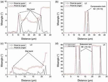
Fig.6.Grain orientation difference along the lines marked in Fig.5:(a)L1,(b)L2,(c)L3,and(d)L4.
particular,the elongation of sample B was twice as high as the elongation of sample A.The difference of the mechanical properties between sample A and sample B can be ascribed to a differentiated microstructure of the specimens,including matrixα-Mg grains,β-phase,and porosities noted above.This will be discussed in detail in the following section.
4.Discussion
According to the experimental results,due to a significant ESCs collecting effect of the flow buffer designed in the improved flow distributer,much less ESCs were observed in the microstructure of sample B,resulting in a finer and more uniform size of theα-Mg grains compared with that of sample A.Based on the Mg-Al binary phase diagram and classical solidification theory,theβ-phase and porosities/shrinkage formed during the last solidification stage of magnesium alloy,mainly at the grain boundary ofα-Mg grains.Consequently,more networkβ-phase with larger size was observed in the microstructure of sample A,while theβ-phase mostly revealed a dispersed and round morphology in the microstructure of sample B.Similarly,more gas-shrinkage pores formed in the interdendritic region or at the grain boundary of coarse ESCs in sample A,while the porosities revealed a more dispersed and island-shrinkage morphology in the microstructure of sample B.
Due to the difference in terms of morphology and size of the microstructure features,including matrixα-Mg grains,β-phase and porosities,their deformation behaviors exhibited in two types of the samples were quite different during tensile deformation.As for theα-Mg grains,it can be found that dislocation slip was prone to occur in the coarseα-Mg grains,especially in the ESCs of sample A.This was because theα-Mg grains with large size could provide relatively wide interior space for the slipping of dislocations.In contrast,the dislocation slip was difficult to occur in theα-Mg grains with small size,since the grain boundary could impede the movement of dislocations and the grain boundary density was heightened with the decrease of the size ofα-Mg grains.From this aspect,the strength of sample B would be higher than that of sample A.Here,the explanation stated was just the crucial viewpoint of the well-known Hall-Petch theory[35,36].Though dislocation slip was inhibited in the fine grains which led to a poor deformation ability of the grains themselves,other important deformation modes,such as grain boundary slipping and grain rotation would play an important role in the coordination of intergranular deformation for polycrystalline metals[37].This was just the reason why grain refinement could improve both the strength and ductility of polycrystalline metals at room temperature.

Fig.7.Grain orientation map of the sample B obtained via EBSD:(a,b)as-cast,and(c,d)deformed.
With regard to theβ-phase,since it was hard and brittle,and difficult to be plastically deformed,cracks would pass through and fracture the networkβ-phase,whereas bypass the islandβ-phase by detaching it from the surroundingα-Mg grains.It can be concluded that the comprehensive mechanical properties of sample B would be higher than those of sample A due to the strengthening effect of the islandβ-phase with a dispersed and round morphology through bypassing mechanism of cracks.
As one type of the major defects in die cast samples,the porosities were much harmful to the performance of castings.Firstly,porosities would reduce the efficient force bearing area of casting.Secondly,large stress concentration may be caused by the porosities particularly with complex morphology.Since the area fraction of porosities at the cross section of die castings was generally lower than 3%[38],the stress increment in the material was relatively small induced by the reducing of the efficient force bearing area.In other words,the effect of porosities on the fracture behavior and mechanical properties of die castings was implemented mainly by stress concentration,while the local stress at the tip region of porosities may be several times higher than the average stress at the cross section of castings.Here,an empirical formula proposed by Brown and Srawley was used to calculate the stress intensity factor(K)by the following Eqs.(7)and(8):[39]

whereWrepresents half of the width of a finite plate.adenotes half of the crack length at the center of the plate.σis the applied tensile stress.Assuming that the porosities are the crack initiation sites during tensile deformation,the crack lengths are equal to the equivalent diameters of different porosities,and the specimen is simplified as a finite plate with some cracks.Accordingly,the stress intensity factors induced by porosities in sample A/B were calculated and listed in Table 3.It can be found that both the average and maximum stress intensity factors in sample A were larger than those of sample B,which suggested that cracks were more inclined to initiate from the complex porosities with large size in sample A.

Table 3Stress intensity factors induced by porosities in sample A/B.

Table 4Calculated and measured ultimate tensile strength of sample A/B.

Fig.8.Grain orientation difference along the lines marked in Fig.7:(a)L5,(b)L6,(c)L7,and(d)L8.
To quantitatively estimate the effect of porosities on the strength of die cast samples,a model proposed by Biswas et al.was applied as shown in Eq.(9)[40].In this equation,σFis the ultimate tensile strength of die cast samples,σF0represents the ultimate tensile strength of a porosity-free sample,fPdenotes the volume fraction of porosities in die cast samples,andmis the exponent.Table 4 shows the corresponding calculated results.Here,the values ofσF0andmwere chosen according to the previous works conducted by Biswas et al.It can be illustrated that the calculated ultimate tensile strength was much close to the measured result of both sample A and B.Meanwhile,a small increase in the volume fraction of porosities would lead to a dramatic decrease of the ultimate tensile strength comparing sample A with sample B.


Fig.9.Statistics of the orientation difference in α-Mg grains of(a,b)sample A and(c,d)sample B.(b)and(d)amplified views of the rectangle regions marked in(a)and(c),respectively.

Fig.10.Porosity morphology in(a–c)sample A and(d–f)sample B before and after tensile deformation.(a)and(d)2D slice images scanned by X-ray tomography,while(b,c)and(e,f)3D images reconstructed by VGStudio Max 2.0 software.

Fig.11.Illustration of the crack propagation and failure behavior in sample A/B caused by porosities.
As for the tensile ductility of die cast samples,a formula similar to Eq.(9)was also proposed by Biswas et al.to establish the relationship between the elongation to fracture and the volume fraction of porosities.The discrepancy between this formula and Eq.(9)was just that the specific values of the exponent were different.A higher value of the exponent in this formula suggested that for particular decrease in the volume fraction of porosities,the relative increment in the elongation to fracture would be higher than the increment in the fracture stress.However,further studies showed that the tensile ductility of die cast samples depended not only on the porosity volume fraction but also on the porosity size and the mechanical properties of matrix,which was reflected in a modified Brown–Embury model as shown in Eq.(10)[41].This model predicted the elongation to fracture of the samples(εf)from information such as mean porosity radius(r),crack-tip radius(ρ),volume fraction of porosity(fP),elastic modulus of the alloy(EP),and yield strength of the samples(σy).It can be seen that the model took into account the local porosity characteristics in different regions of the specimens to determine the critical local strains that would cause fracture in these regions of the specimens.Since the specific value of crack-tip radius was difficult to measure,assuming that the value ofr/ρin sample A was equal to that in sample B,in this case a lower volume fraction of porosities in conjunction with a higher yield strength led to a higher elongation to fracture of sample B than that of sample A.


Fig.12.In situ observation of the crack propagation path in(a,b)sample A and(c,d)sample B.(a)and(c)before tensile deformation,while(b)and(d)during tensile deformation.
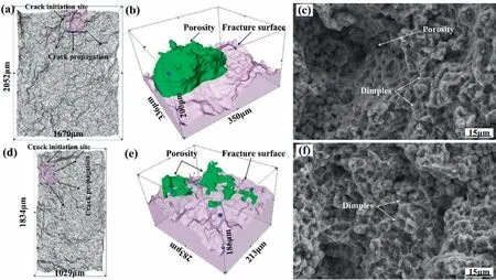
Fig.13.Fracture morphology of(a–c)sample A and(d–f)sample B.(a)and(d)2D slice images scanned by X-ray tomography,(b)and(e)3D images reconstructed by VGStudio Max 2.0 software,while(c)and(f)SEM images of the fracture surface.

Fig.14.Mechanical property testing results of sample A/B:(a)stress-strain curves of the specimens,and(b)comparison of the mechanical properties in terms of ultimate tensile strength,yield strength and elongation.
5.Conclusions
In this study,the deformation behavior of the heterogeneous microstructure of die cast AZ91D magnesium alloy and its effect on the mechanical properties of die castings were investigated.The main conclusions can be summarized as follows:
(1)The predominant deformation behavior inα-Mg grains was dislocation slip,supplemented by deformation twinning.Dislocation slip was difficult to occur in theα-Mg grains with small size,since the grain boundary could impede the movement of dislocations.
(2)Cracks were prone to initiate from complex porosities with large size,at the tip region of which large stress concentration generally appeared during tensile deformation.When the gas-shrinkage pore acted as the crack initiation site,it grew and kept expanding in the train of crack initiation,by which means the crack propagated approximately perpendicular to the tensile direction.When the crack initiated from the island-shrinkage,it propagated in the form of coalescence and linkage of the dispersed island-shrinkage.
(3)When the crack was in contact with theβ-phase,it would pass through and fracture the networkβ-phase,whereas bypass the islandβ-phase by detaching it from the surroundingα-Mg grains.
(4)The mechanical properties of die castings were remarkably influenced by the microstructure of die cast AZ91D magnesium alloy,especially the distribution and size ofα-Mg grains,β-phase and porosities.A more homogeneous microstructure consisting of fine and uniformα-Mg grains,as well as dispersedβ-phase and porosities,would bring about higher mechanical properties of die castings.
Declaration of interests
The authors declare that they have no known competing financial interests or personal relationships that could have appeared to influence the work reported in this paper.
Acknowledgments
This work was financially supported by the National Natural Science Foundation of China(No.51805389),Natural Science Foundation of Hubei Province of China(No.2018CFB210)and 111 Project(B17034).
 Journal of Magnesium and Alloys2022年7期
- Journal of Magnesium and Alloys的其它文章
- High-performance magnesium-based thermoelectric materials:Progress and challenges
- Effects of heat treatment on the corrosion behavior and mechanical properties of biodegradable Mg alloys
- Multi-solute solid solution behavior and its effect on the properties of magnesium alloys
- Calcium phosphate conversion technique:A versatile route to develop corrosion resistant hydroxyapatite coating over Mg/Mg alloys based implants
- The role of solutes in grain refinement of hypoeutectic magnesium and aluminum alloys
- Characterization on the formation of porosity and tensile properties prediction in die casting Mg alloys