
Asynchronous Observer Design for Switched Linear Systems: A Tube-Based Approach
2020-02-29 14:16MinghaoHanRuixianZhangLixianZhangYeZhaoandWeiPan
Minghao Han,, Ruixian Zhang, Lixian Zhang,,Ye Zhao,, and Wei Pan,
Abstract—This paper proposes a tube-based method for the asynchronous observation problem of discrete-time switched linear systems in the presence of amplitude-bounded disturbances.Sufficient stability conditions of the nominal observer error system under mode-dependent persistent dwell-time (MPDT)switching are first established. Taking the disturbances into account, a novel asynchronous MPDT robust positive invariant(RPI) set and an asynchronous MPDT generalized RPI (GRPI)set are determined for the difference system between the nominal and disturbed observer error systems. Further, the global uniform asymptotical stability of the observer error system is established in the sense of converging to the asynchronous MPDT GRPI set, i.e., the cross section of the tube of the observer error system. Finally, the proposed results are validated on a space robot manipulator example.
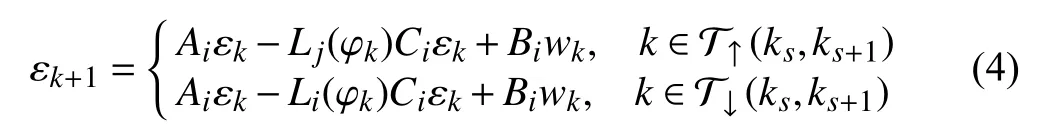
I. INTRODUCTION
THE asynchronous phenomenon in switched systems commonly results from delays caused by detecting mode switchings as well as designing new controllers and observers for unknown modes at runtime. As shown in [1], the masterslave coordination system often switches among high-gain and low-gain controllers when the slave changes from being in a contact-free motion to interacting with a stiff environment, or vice versa. The inevitable delay caused by this controller switching is detrimental to system stability and performance. Another example can be found in the framework of adaption and learning via multiple models switching [2],where back-up models are needed to deal with unpredictable changes of the environment on top of the predefined models.Similar to other typical time-delay systems, time delays in the asynchronous switching may also cause performance degradation and even system instability, as shown in the studies of different topics of such systems, [3]-[15], to name a few.
A fundamental problem in the area of asynchronous switched systems is disturbance handling, and the difficulties largely depend on the types of the disturbances. For the systems with energy-bounded ones, i.e.,l2norms, results have been well-established in the literature [16], [17]. Note that thel∞disturbances are common in many practical systems, such as valve control systems [18], robotic control systems [19],aircraft flight control systems and shipping navigation control systems [20]. To our best knowledge, the amplitude-bounded disturbances, i.e.,l∞norms, have not been investigated for the asynchronous switched systems yet. An effective way to handlel∞disturbances is the tube based method, for example,in stabilization [21] and advanced model predictive control[22].
The crux of applying the tube-based method to thel∞disturbance rejection problem for switched systems is to guarantee that the error system states remain within certain formally-defined robust sets. To this end, a robust positive invariant (RPI) set is determined such that the state trajectory of the error system always remains within the RPI set at switching instants while staying within an outer robust set during subsystem evolvement [23]. This outer robust set is named as the generalized robust positive invariant (GRPI) set and determined based on the RPI set. Then, by shifting the center of the GRPI set from the origin to the nominal trajectory of the switched system at each instant, a tube that contains all possible state trajectories is constructed and stability condition is established accordingly. Results determining the RPI set can be found in the cases of persistent dwell-time (PDT) [21], dwell-time (DT) [23], and average dwell-time (ADT) switching [24]. In the context of asynchronous switching, the aforementioned procedures would become more challenging than in the synchronous case,due to the complicated computation of RPI and GRPI sets.
Motivated by the observations above, this study focuses on the asynchronous observation problem for discrete-time switched linear systems with amplitude-bounded additive disturbances. The switching signals pertain to a class of modedependent persistent dwell-time (MPDT) switching and the disturbance is considered to bel∞finite. The contributions of this paper lie in that: 1) Sufficient stability conditions of the nominal observer error system under the asynchronous MPDT switching are proposed and an algorithm is designed to determine the asynchronous observer solution. 2) The RPI and GRPI sets in the asynchronous MPDT switching case are first determined in this paper and the corresponding algorithm is designed. 3) Based on the determined asynchronous MPDT GRPI set, the stability condition of the disturbed observer error system is obtained.
The remainder of this paper is organized as follows. In Section II, the problem formulation is presented and basic concepts are given. The detailed derivations of the proposed results are given in Section III. An application of the obtained results to a space robot manipulator is given in Section IV,and Section V concludes this paper.
Notations:In this paper, Rnrefers to thendimensional Euclidean space; ‖·‖ refers to the Euclidean vector norm;Z and Z+denote the sets of integers and non-negative integers respectively; Z≥aand Z[a,b]denote the sets {k∈Z|k≥a} and{k∈Z|a≤k≤b}, respectively, 0 ≤a≤b. The Minkowski sum and Pontryagin difference of two compact sets, Θ1⊆Rnand Θ2⊆Rn, are Θ1⊖Θ2={x1+x2|x1∈Θ1,x2∈Θ2} andΘ1⊖Θ2={x|x+x2∈Θ1,x2∈Θ2} , respectively.co{·} denotes the convex hull of a set. Let Bndenote a unit ball set {x∈Rn|‖x‖2≤1}. A function κ:[0,∞)→[0,∞) is an K∞class function if it is strictly increasing, continuous, unbounded and κ(0)=0. For a vectorx∈Rnand a set Θ ⊆Rn, the distance betweenxandΘ is defined asdenotes the set ofn×nsymmetric positive (semi-positive) definite matrices. In addition, diag{X,Y} stands for a block-diagonal matrix where diagonal entries areXandY. Symbol * is used as an ellipsis for the terms that are introduced by symmetry.Iand0 represent the identity matrix and zero matrix, respectively.Matrices, if their dimensions are not explicitly stated, are assumed to be compatible for algebraic operations.
II. PRELIMINARIES AND PROBLEM FORMULATION
Consider the discrete-time switched linear systems and Luenberger observer described as follows:
In this paper, σ(k) is considered to belong to the set of mode-dependent persistent dwell-time (MPDT) switching.The concept of MPDT is given in the following definitions.instantsk0,k1,...,ks,... withk0=0. A positive constantτ(respectively τi) is 1) the dwell-time if for allk≥0,ks+1-ks≥τ; 2) the mode-dependent dwell-time of theith mode of system (1) if for allk≥0 such that σ(k)=ifork∈[ks,ks+1),ks+1-ks≥τi.
Definition 1 [27]:Consider system (1) and switching
Definition 2 [21]:Consider system (1) and switching instantsk0,k1,...,ks,... withk0=0. If there exist infinite disjoint intervals of length no smaller than τion which σ=i,and consecutive intervals with the same property are separated by no more thanT, then τiis called the mode-dependent persistent dwell-time andTis called the period of persistence.
The switching sequence satisfying Definition 2 is coined as an MPDT switching sequence. Then,[τ]T:={τ1,τ2,...,τN}denotes the set of MPDT τi’ s andis the set of all admissible MPDT switching sequences till timek.
As illustrated in Fig. 1, the interval composed of a dwelltime portion and a persistence portion can be regarded as an MPDT phase [21].ksis the initial instant of thesth phase as well as the instant switching into thesth phase. In the dwelltime portion, one subsystem Ωσ(ks)is maintained for at least τσ(ks). Whereas in the persistence portion, more than one switchings happen and each subsystem sustains for the time duration ofwhereis the switching instant betweenandis the running time of the persistence portion in thesth phase,
where Q (ka,kb) denotes the number of switchings between two instants,aandb∈Z.
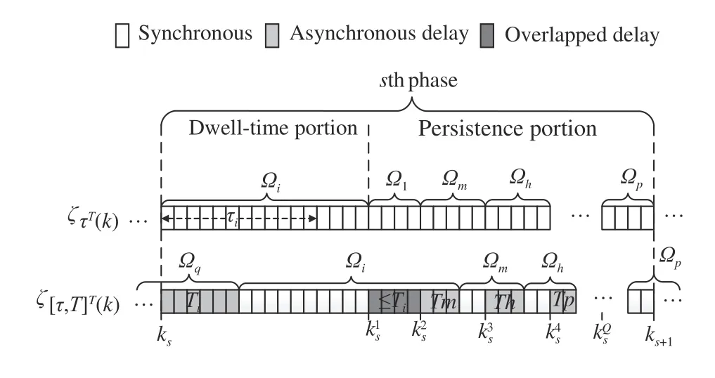
Fig. 1. General illustration of an MPDT switching sequence and an asynchronous MPDT switching sequence.
In the proposed observer (2), the QTD observer gainLσ(k)(φk) is scheduled by the index φk, which is computed online as in [17]. ∀ σ(k)=i∈I,
1) in the dwell-time portion
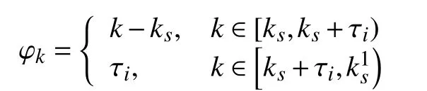
2) in the persistence portion

In the case of synchronous observation, the observer always switches simultaneously with the switched linear system (1);however, this doesn not hold in most practical applications[28]. Consider the case where a new subsystem is identified at runtime, and the observer gains need to be recalculated online accordingly. In this case, if the switched linear system (1)consists of numerous high-order subsystems, solving the observer design problem online could take more than one sampling period, likely causing asynchronous switching between the system modes and observer gains. In the presence of asynchronous delays, the observer becomes
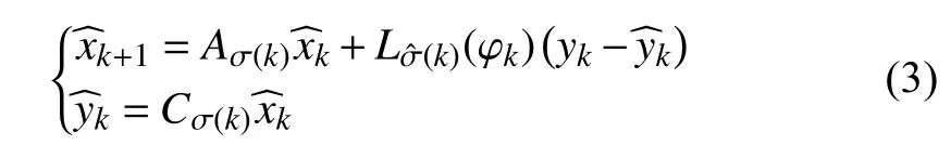
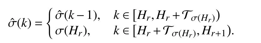
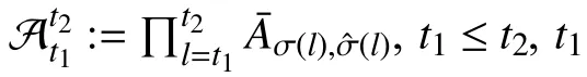
The asynchronous delay caused by the identification of switching and online computation of observer gains for the new subsystem is denoted byLetanddenote the set of unmatched and matched periods in [a,b),respectively. Similar to τ, T is also mode-dependent and the set of asynchronous mode-dependent persistent dwell-time is denoted byGiven the MPDT switching signal σ(k), the observer switching signalcan be derived according to the following rule:
The switching sequence composing ofis called an asynchronous MPDT switching sequence. The set of all admissible asynchronous MPDT switching sequences tillkis denoted by
The relation between σ(k) andis illustrated in Fig. 1.In the dwell-time portion, only one switching occurs and waits for at leastmoments, causing only one period of asynchronous delay (seeHowever in the persistence portion, more than one switching could occur. The asynchronous delays invoked by fast switchings may be overlapped (i.e., a new switching happens before the end of the previous delay, seeandor cover the entire persistence portion (i.e., new switchings happen succeedingly before or at the end of previous delays).
Fig. 2 provides an illustration of how the proposed observer is executed in practice. This paper is concerned with the observer design and as such the corresponding parts therein connected by the blue arrows, an observer-based controller is also shown for the readers to have a comprehensive view of the close-looped system. In the space robot manipulator example in the sequel, the observer-based controller will be used to only maintain the system stability, but will not be discussed in detail in the main results.
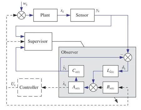
Fig. 2. Illustration of the observer structure and signal flow. The blue lines show the closed-loop observed system structure, and the dashed lines are used to show the structure when the observer-based controller is involved.
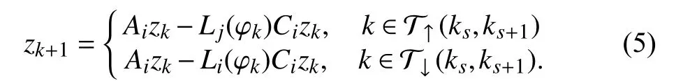
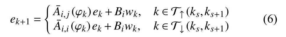
Let, thedifference systembetween the disturbed observer error system (4) and the nominal system (5) becomes
To establish the stability criterion for the systems above, we need the following definitions:
Definition 3 [29]:A setO⊂Rnxis said to be a robust positive invariant (RPI) set for systemxk+1=f(xk,wk),wk∈W, ifxk∈Oimpliesxt∈Ofor anywt∈W,t∈Z≥k+1.
Definition 4:A setis said to be an asynchronous MPDT RPI set for system (6) with asynchronous MPDTifimpliesfor every admissible switching in ζ[τ,T]T(t) withwt∈W,t∈Z≥k0,
Definition 5:A setis said to be ans∈Z≥1.asynchronous MPDT generalized robust positive invariant(GRPI) set for system (6) with asynchronous MPDT setifimpliesfor every admissible switching inand for anywt∈W ,t∈Z≥k+1, whereis an asynchronous MPDT RPI set for system (6).
Definition 6 [30]:System (5) is globally uniformly asymptotically stable (GUAS) under certain switching signals σif for initial conditionzk0, there exists a class of K∞function κ such that the solution of the system satisfies ‖zk‖≤κ(‖z0‖),∀k∈Z≥k0and ‖zk‖→0 ask→∞.
Definition 7:An asynchronous MPDT GRPI set⊆Rnxis said to be GUAS for system (6) with asynchronous MPDT switching, if for allandask→∞, whereκ ∈K∞.
Considering all the asynchronous phenomena shown in Fig. 1, this paper aims to design a full-order state observer for the switched linear system (1) subject to asynchronous MPDT switching regularities, and find an asynchronous MPDT GRPI set for the resulting difference system (6) such that the disturbed observer error system (4) is GUAS in the sense of Definition 7.
III. MAIN RESULTS
In this section, we first investigate the stability criteria and the QTD observer design for the nominal observer error system (5) in the presence of asynchronous delay, under MPDT switching. Subsequently, the asynchronous MPDT RPI set and asynchronous MPDT GRPI set of the difference system (6) are determined. Finally, the stability of the disturbed observer error system (4) is established in the sense of Definition 7. The relations between the criteria obtained in this section are illustrated in Fig. 7 in Appendix A. Most of the proofs in the first subsection can also be found in Appendix B.
A. Nominal Systems
A class of QTD Lyapunov functionsVi(xk,k), allowing the energy to increase when the unmatched observer is activated,are considered to establish the stability criterion for the nominal system in nonlinear cases. The energy increment should be compensated by the decrement during matched stages, such that the overall system is stable. To this end, the increasing and declining rates are restricted below certain values in the following lemma.
Lemma 1:Consider a discrete-time switched systemxk+1=fσ(k)(xk) , 0 <α <1, β >0 and µ≥1 are given constants. For a prescribed period of persistenceT, suppose that there exist a family of functions→R , σ(k)∈I , and two class K∞functions κ1and κ2such that:


∀(i,j)∈I×I and
where
Then the switched system is GUAS for asynchronous MPDT switching signals satisfying

Proof:See Appendix B.
Remark 1:It is worth noting that λidenotes the worst-case energy coefficient rate during a phase, when the system works asynchronously during the period ofTin the persistence portion, resulting in the Lyapunov function to be increasing to the greatest extent. Thus, the system is guaranteed to be stable in the presence of consecutive asynchronous switchings as well as the overlapped asynchronous delays, as displayed in Fig. 1.
Next, the quasi-time-dependent (QTD) Lyapunov function is defined as, and the stability criterion for the nominal observer error system (5) is established in the following theorem.
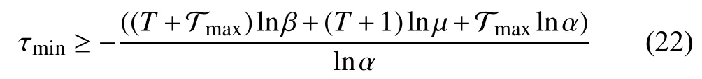
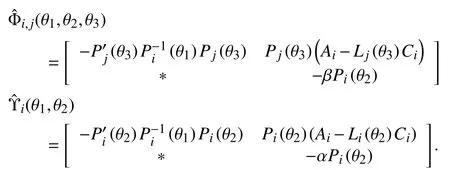
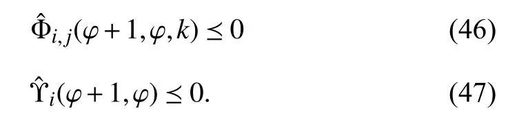
Theorem 1:Consider system (5), suppose there exist consta nts 0 <α <1, β ≥1, µ≥1 and matricesandsuch that
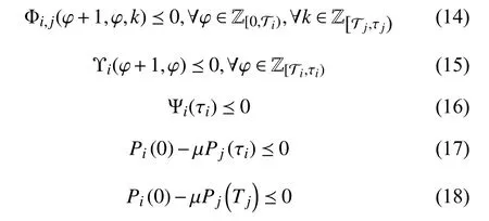
hold, whereand
Then the system (5) is GUAS for asynchronous MPDT signals satisfying
Proof:See Appendix C.
Remark 2:Since the asynchronous switching could occur between any two subsystems at unpredictable instants, all possible combinations of time schedules and subscripts in inequalities (14) are involved to restrict the energy increment caused by the asynchronous switching.
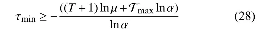
Remark 3:For given constants α, β , µ, the inequalities in Theorem 1 are linear matrix inequalities (LMI). The subminimal asynchronous MPDT can be obtained through bisection on these constants while guaranteeing a feasible solution for the LMIs.
A noteworthy fact is that if letting∀i∈I, the observer given in Theorem 1 will correspond to the case of synchronous observation. In this case, the synchronous nominal observer error system is obtained by settingandin (5)

To compare with the performance of synchronous observers under asynchronous switching, we also present the QTD synchronous observer design as below. The proof can be obtained by settingin the proof ofTheorem 1 and thus is omitted here.constants 0 <α <1, µ≥1 and matricesand
Corollary 1:Consider system (23), suppose there existsuch that,
server gain is given by
Although the QTD observer formulation presented in Theorem 1is generally less conservative compared to the non-QTD ones [17], the resulting quasi-time-varying close-looped state transition matrix could impede the calculation of invariant sets in the next section. Thus, the non-QTD observer design is presented in the following corollary based on the φkindependent Lyapunov functionthe proof can be obtained in a similar vein to the one of Theorem 1 and thus is omitted.
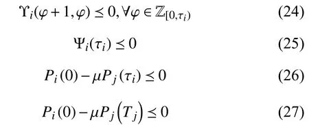
Corollary 2:Consider system (5), suppose there exist consta nts 0 <α <1, β ≥1, µ≥1 and matricesandsuch that
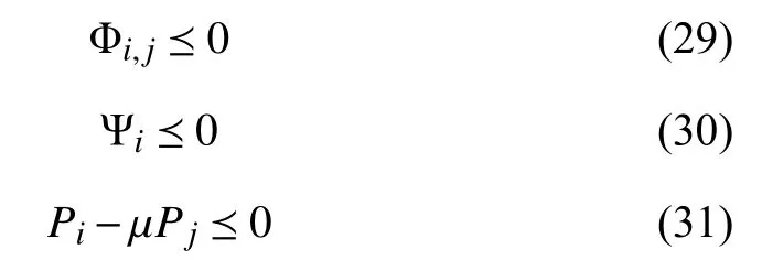
hold, where
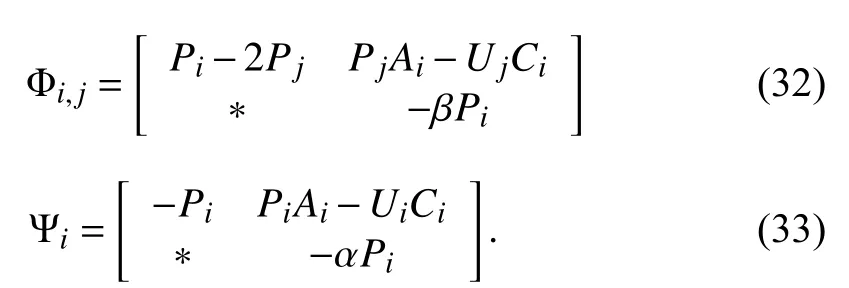
Then the system (5) is GUAS for asynchronous MPDT switching signals satisfying
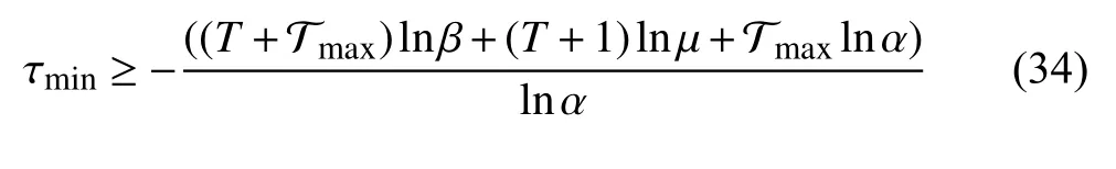

Remark 4:The feasible solutions of Corollary 1 and Corollary 2 can be obtained following a similar procedure to Algorithm 1by replacing the cost functions with (28) and(34), the constraints with (24)-(27) and (29)-(31),respectively.
Next, a numerical example is introduced to illustrate the validity of theoretical results in this section, as well as the discussions above.
Example 1:Consider a switched linear system with two subsystems
Our aim is to design a QTD observer based onTheorem 1 and Corollary 1 for the system (36). To illustrate the effectiveness of the proposed observer design, a fairly nonconservative asynchronous MPDT setis constrained asSinceis involved in, it is possible that the system runs in the unmatched condition for the greater part of the time. For the observer designed by Theorem 1, the constants searched through bisection are α=0.5, β=1.05, µ=1.05. For Corollary 1, α=0.3 andµ=1.05.
Due to the fact that the subsystems of (36) are both unstable, a non-switching observer-based state-feedback controller is designed to protect the closed-loop system from divergence and the controller gain is obtained asK=[-2.259,-4.239].
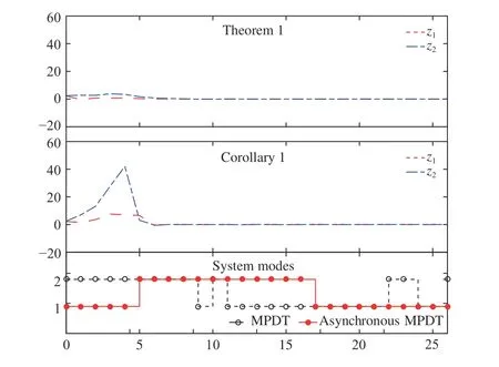
Fig. 3. State responses of the nominal observer error system (36), with observers designed by Theorem 1 and Corollary 1 under asynchronous MPDT switching.
As demonstrated in Fig. 3, the asynchronous delays occupy more than half of the domain (see the bottom). When the synchronous observers are applied, the state response tends to become unstable and an overshoot appears in the presence of asynchronous switchings, while the asynchronous observers designed by Theorem 1 stabilizes the nominal observer error system of system (36) effectively.
B. Systems With Bounded Additive Disturbances
In this subsection, to address the stability of the system (6)in the sense of Definition 7, we will first determine an asynchronous MPDT RPI set and an asynchronous MPDT GRPI set. The GRPI set is developed on the basis of an RPI set, thus the form and existence proof of the RPI set need to be presented first. Given the observer gains determined by Corollary 1as (35), the system (5) is GUAS under asynchronous MPDT switching. In the following theorem, the existence of an asynchronous MPDT RPI set is proved.
Theorem 2:If system (5) is GUAS with asynchronous MPDT, then there exists an asynchronous MPDT RPI setfor system (6).
Proof:First, define a setdenoting all possible disturbance effects on system (6) duringvth phase, whereis the length of dwell-time portion ofvth phase andidenotes the subsystem during the dwell-time. Let
Iterating (38) fromvto 0,v∈Z≥1, one gets
andOv⊆Γv. Given the fact that system (5) is GUAS with asynchronous MPDT setit follows thatis asymptotically stable under any admissible switching sequence inwhereWith a similar use of the finite set Θiin [23], the evolution of subsystems fromkvtokv+r,r∈Z≥1, under any switching sequence incan be represented by the sequential product of matrices inConsequently, there exist constants ϵ ∈(0,1) and η >0 satisfyingsuch thatConsideringO0=Λ or {0}, Λ ⊆S, it yields that

Therefore, by (38) and (39),and thatOvis bounded byasv→∞ are guaranteed,respectively. Thus there exists adependent limit setO∞for the set sequence {Ov|v∈Z+}. In consequence, for system (6), for anyfor any admissible asynchronous MPDT switchingwithw(k)∈W,k∈Z≥1.
By the use of non-QTD observer gains, the evolution of the system (6) under all admissible switching sequences can be represented by combinations of matrices inwith a finite set Θi, while such comparable sets will not exist in the QTD case [21].
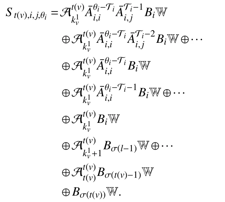
To compute the asynchronous MPDT RPI setone step reachable set of X in subsystem Ωiwith observerLjis defined first,and anN-step reachable set is accordingly defined aswhereThe expanded form isIn order to compute the reachable set under all admissible asynchronous MPDT switching sequences, three reachable-set operatorsandare defined for the periods of asynchronous delay, dwell-time portion and persistence portion respectively as follows:
wherek∈Z[0,t]. Based on Theorem 2, the algorithm for computation of the asynchronous MPDT RPI setis proposed as follows:
Algori thm 1 Computation ofO([τ,T]T)
It should be noted that the convergence of Algorithm 1 is guaranteed by the existence ofO([τ,T]T). By Definition 4, ife0∈O([τ,T]T),ekonly has to stay insideO([τ,T]T) at switching instants {ks|s∈Z+}, so it is allowable that the states pass in and outO([τ,T]T) multiple times during each phase.Consider the reachable sets in the asynchronous MPDT switching case, during dwell-time portions, the states are driven intoO([τ,T]T) owing to the effect of matched observers, while in persistence portions and asynchronous observation, frequent switching and unmatched observers generally take an opposite effect. It yields thatandare not necessarily the subsets of
Thus, let
Ifwe haveMoreover, the asynchronous MPDT GRPI set is obtained as, based on which the stability criterion of (6) can be established in the sense of Definition 7 in the following theorem.
Theorem 3:Consider the observer error system (4). Suppose that a set of non-QTD observers exist for the nominal system(4) with asynchronous MPDT switchingThen the setis GUAS for the system (4).
Proof:If there exist a set of observers such that system (5)is GUAS with thesatisfying (22), then it follows from Definition 6 thatandask→∞, where. Withand, it follows thatandask→∞. For anyz0and ε0, there exists a positive constant α such that α ≤thus we haveandκ(·/α)∈K∞, which indicates thatis GUAS for the system (4) in the sense of Definition 7.Remark 5:For the defined and calculated asynchronous MPDT GRPI setonce the state trajectory of system (4) entersit will always remain inside.Accordingly, let the asynchronous MPDT GRPI setbe the cross section of a uniform tube, of which the center is the state of the nominal observer error system (5), then all the trajectories of the disturbed observer error system (4) will be contained in the uniform tube.
Remark 6:When the union operations related to the asynchronous switching in the calculation of asynchronous MPDT RPI setand GRPI setare removed, the sets in the synchronous switching case will be obtained. Thus the MPDT RPI and GRPI sets in the case of synchronous switching can be regarded as particular cases of the asynchronous ones and the asynchronous sets are more general than the synchronous ones.
To show the effectiveness of Theorem 2 and Theorem 3, a numerical example is presented here.
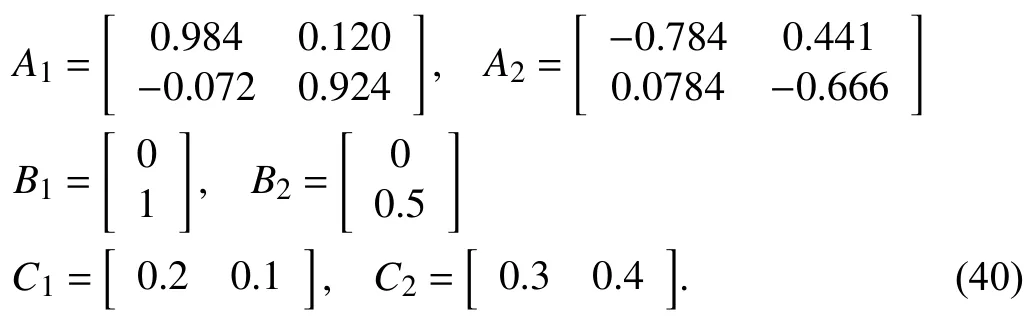
Example 2:Consider a switched linear system with two subsystems
The aim is to design a non-QTD observer and calculate the corresponding asynchronous RPI and GRPI sets for the system (40). With the searched constants α=0.3025,β=1.2506 and µ=1.2502, the non-QTD observer gains are obtained as

Let the disturbance input be restricted asthe asynchronous MPDT RPI setOvand GRPI setare derived and illustrated in Fig. 4. We suppose that there exists a persistence portion before the first phase starts, causingO0to be non-zero, which is shown in Fig. 4 (a). It is shown thatOvalmost converges after 10 iterations and eventually reaches convergence at the 14th iteration. The state trajectory of the difference system in (40) is illustrated in Fig. 4 (b) . It is observed that once the trajectory entersthe states always remain inat switching instants and stay inside the GRPIall the time, though the trajectory shows some level of chattering when asynchronous delays or fast switching occurs.
IV. EXPERIMENT WITH THE SPACE ROBOT MANIPULATOR
In this section, our method is tested on a space robot manipulator (SRM) model to demonstrate the validity and applicability. Let us consider an SRM model with the following rigid-body dynamics equations as proposed in [31]
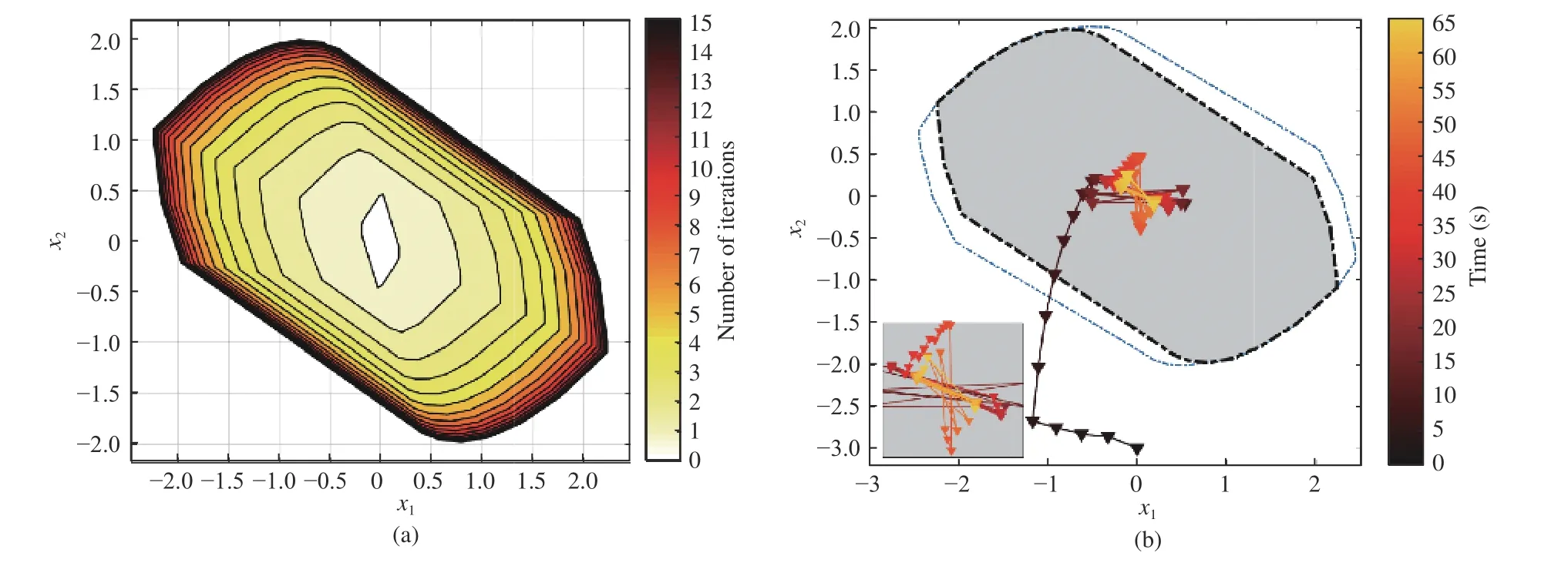
Fig. 4. Visualization of MPDT GRPI set and evolution of the difference system. (a) shows the computation process of Algorithm 2, where the white set denotes the initial set O0 and the darkest set denotes In (b), evolution of state trajectory is demonstrated in 2D view, where the inner shadowed set isand the outer blue dashed line denotes the A zoom-in display is presented in the bottom of (b) to have a detailed view of the state trajectory.
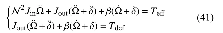
where Ω , δ,TeffandTdefare variables representing the joint angle of inertial axis, the joint angle of the output axis, the effective joint input torque and deformation torque of the gearbox, respectively; N is the gearbox ratio and β is the damping coefficient;JinandJoutstand for the inertia of the input axis and output system, respectively. As in [31], the actuator model of the motor plus the gearbox is formulated as follows:

whereKtdenotes the motor torque constant andcdenotes the spring constant; variableicstands for the motor current, which is also the control inpututo the system. We assume no drivetrain loss in the model.
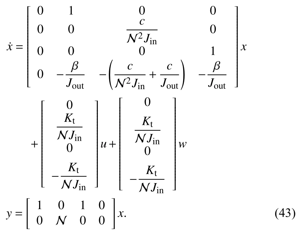
It is known that the motor torque constantKtand inertia of the input axisJinmay change abruptly when the SRM system encounters failures. Then (43) can be modeled as a switched system under persistent dwell-time switching. In this paper,we consider generalizing the allowable switching to a relatively broader scope by MPDT switching. Suppose there are two modes in the switched system, and the corresponding parameter values are

To apply our method to the continuous model, the system(43) is discretized with a sampling periodTs=0.1(s) and the asynchronous MPDT switching is constrained asandT(s)≤4. The non-QTD asynchronous observers are designed as in Corollary 2. By settingin Corollary 1, non-QTD synchronous observers are obtained and applied as well for comparison. With disturbances restricted asthe asynchronous RPI setand GRPI setare obtained and shown in Fig. 5. Given the fact that the SRM model has four dimensions, resulting in thatandcan not be visualized directly, the figures shown here are the projection ofandin two orthogonal planes.
The discretized system is unstable without control input and performance of the observer is difficult to determine in this case. Hence, an observer-based non-switching state feedback controlleris designed by solving a constrained feasibility problem in the form of LMIs, and implemented as in Fig. 2. The controller gain is obtained asK= [6.7876,13.9042, 448.0034, 22.9035]. The constants searched by bisection are also listed here: for the observer designed by Corollary 2, α=0.9612, β=1.01 and µ=1.0096; for that of Corollary 1, α =0.05 and µ =1.25.
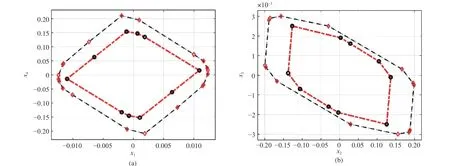
Fig. 5. Visualization of the obtained asynchronous RPI set(the red dashed line) and GRPI set (the blue dashed line) of the SRM system. (a) Projection of and in the plane formed by x1 and x4; (b) Projection of and in the plane formed by x2 and x3.
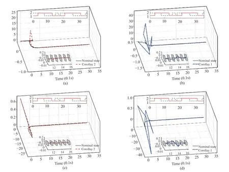
Fig. 6. Evolution of state trajectories of the observer error system of the SRM. The nominal trajectories are drawn in black, while the red and blue dashed lines stand for the trajectories of disturbed observer error system resulting from Corollary 2 and Corollary 1, respectively. To show the four dimensional trajectories, we project them in two orthogonal directions correspondingly with Fig. 5, and time is added as the third dimension generating the three dimensional trajectories. (a) and (b) show the state trajectories in the space formed by x1, x4 and time; (c) and (d) show the state trajectories in the space formed by x2, x3 and time.
The evolution of state trajectories of the disturbed and nominal observer error system with the asynchronous and synchronous observers is shown in Fig. 6, where the four dimensional trajectories are projected in the same manner as in Fig. 5. The convergence in final phase can be found in the zoom-in display in Fig. 6. In the presence of asynchronous delays and disturbances, it is noted that there are larger state overshoots in the synchronous observer case than in the asynchronous one. Additionally, as shown in the zoom-in display, the asynchronous observers are capable of attracting the observer errors intoand maintaining it consistently, while the synchronous ones fail.
Remark 7:The experiment and examples above show that our approach is effective for the observation of switched systems in presence of asynchronous switchings andl∞disturbances. However, it should be noted that when applied to systems with a large number of subsystems, the increased number of constraints may inherently affect feasibility of the LMIs and application of the proposed method.
V. CONCLUSIONS
The asynchronous observer design problem of a class of discrete-time switched linear systems with additivel∞disturbances under MPDT switching is investigated. The existence condition of asynchronous QTD observers for the nominal observer error system to be GUAS is proposed. A numerical example is presented to demonstrate the effectiveness of asynchronous observers compared to the synchronous ones. In the presence ofl∞disturbances, the asynchronous MPDT RPI set and the corresponding algorithm are presented, ensuring that the state of the difference system remain inside the RPI set at switching instants. Furthermore,the asynchronous MPDT GRPI set is determined as the cross section of a uniform tube of the observer error system, of which the asymptotic stability is demonstrated in the sense of converging to the asynchronous MPDT GRPI set. Eventually,an SRM example is introduced to validate the effectiveness of the proposed method.
APPENDIX A RELATION GRAPH OF THEOREMS AND COROLLARIES
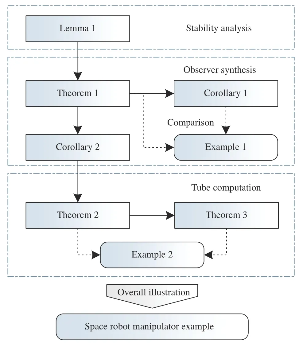
Fig. 7. Relation among the obtained criteria.
The relationship among the proposed theorems and corollaries is given in Fig. 7. Lemma 1 is the basis for all other later derivations and provides a sufficient criterion for the GUAS of switched systems under general asynchronous MPDT switching. In Theorem 1, considering a class of quadratic QTD Lyapunov functions, the design of the asynchronous QTD observer is proposed guaranteeing the nominal observer error system to be GUAS. Let the asynchronous delays in Theorem 1 be zero, the synchronous observer design is obtained in Corollary 1. Based on Theorem 1, Corollary 2 gives the non-QTD asynchronous observer design. In Theorem 2, the asynchronous MPDT RPI set is determined by applying the results developed in Corollary 2.Based on the proposed asynchronous MPDT RPI set, the asynchronous GRPI set is further developed. Theorem 3 proves that the asynchronous MPDT GRPI set is GUAS for the observer error system in the sense of Definition 7.
APPENDIX B PROOF OF LEMMA I
Proof:First of all, if β <1, then the system falls into the class of switched systems under synchronous switching(where the energy always decays during each subsystem), and this lemma transforms to a stability criterion for the corresponding system to be GUAS [17]. Thus the proof boils down to the caseβ ≥1.
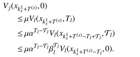
Then, iterating fromtowith the following procedure,one gets
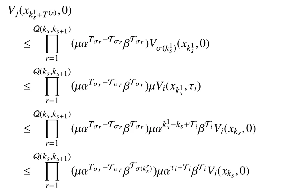
Since β ≥1 >α , it holds thatWe haveLetcombined with(13), one has λmax≤1. Take the fact that a period of persistence may exist before the first phase into account, it followsFrom (7),holds.Thus, with (7)-(12),whereTherefore the global uniform asymptotic stability of the switched systemcan be inferred by Definition 6.
APPENDIX C PROOF OF THEOREM I
Proof:First of all, for matrix∀i∈I, from the fact thatwe haveThus the following inequalities hold:
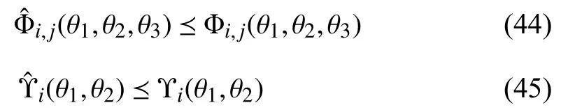
where
With (14), (15), (44) and (45), the following inequalities are guaranteed:
Perform congruence transformation to (16), (46) and (47)withandrespectively. With the Schur complement, one gets (8)-(12)for
With (22) and the fact that 0 <α <1, β ≥1,andit follows thatand (13) is guaranteed. Then by Lemma 1, the nominal observer error system (5) is GUAS for asynchronous MPDT switching signals satisfying (22). ■
 IEEE/CAA Journal of Automatica Sinica2020年1期
- IEEE/CAA Journal of Automatica Sinica的其它文章
- Networked Control Systems:A Survey of Trends and Techniques
- Big Data Analytics in Telecommunications: Literature Review and Architecture Recommendations
- A Stable Analytical Solution Method for Car-Like Robot Trajectory Tracking and Optimization
- A New Robust Adaptive Neural Network Backstepping Control for Single Machine Infinite Power System With TCSC
- Algorithms to Compute the Largest Invariant Set Contained in an Algebraic Set for Continuous-Time and Discrete-Time Nonlinear Systems
- Deep Imitation Learning for Autonomous Vehicles Based on Convolutional Neural Networks