
Wireless Self-Powered Vibration Sensor System for Intelligent Spindle Monitoring
2023-08-14 06:52LeiYuHongjunWangYubinYueShucongLiuXiangxiangMaoandFengshouGu
Lei Yu,Hongjun Wang,★,Yubin Yue,Shucong Liu,Xiangxiang Mao and Fengshou Gu
1Intelligent Sensing and Control of High-End Equipment Beijing International Science and Technology Cooperation Base,Beijing Information Science and Technology University, Beijing, 100192, China
2Machinery Technology Development Co, Ltd.,Beijing, 100044,China
3Centre for Efficiency and Performance Engineering,University of Huddersfield,Queensgate,Huddersfield,West Yorkshire,HD1-3DH,UK
ABSTRACT In recent years, high-end equipment is widely used in industry and the accuracy requirements of the equipment have been risen year by year.During the machining process, the high-end equipment failure may have a great impact on the product quality.It is necessary to monitor the status of equipment and to predict fault diagnosis.At present,most of the condition monitoring devices for mechanical equipment have problems of large size,low precision and low energy utilization.A wireless self-powered intelligent spindle vibration acceleration sensor system based on piezoelectric energy harvesting is proposed.Based on rotor sensing technology,a sensor is made to mount on the tool holder and build the related circuit.Firstly, the energy management module collects the mechanical energy in the environment and converts the piezoelectric vibration energy into electric energy to provide 3.3 V for the subsequent circuit.The lithium battery supplies the system with additional power and monitors’the power of the energy storage circuit in real-time.Secondly, a three-axis acceleration sensor is used to collect,analyze and filter a series of signal processing operations of the vibration signal in the environment.The signal is sent to the upper computer by wireless transmission.The host computer outputs the corresponding X, Y, and Z channel waveforms and data under the condition of the spindle speed of 50~2500 r/min with real-time monitoring.The KEIL5 platform is used to develop the system software.The small-size piezoelectric vibration sensor with high-speed, high-energy utilization, high accuracy, and easy installation is used for spindle monitoring.The experiment results show that the sensor system is available and practical.
KEYWORDS Condition monitoring; self-powered; vibration acceleration sensor; piezoelectric energy harvesting; wireless transmission
1 Introduction
In recent years,the rapid development of science and technology has led to the rapid rise of intelligent perception in the manufacturing industry.Machine tools[1]are the most important processing equipment for the manufacturing industry.As the core processing component of the machine tool,the performance of the spindle directly determines the product quality,industrial productivity and economic benefits[2].Therefore,building a smart spindle will also become the future development trend of the smart manufacturing industry.The intelligent spindle mainly realizes the long-term self-powering function of the online monitoring and sensing system of the spindle state [3], which ensures the normal operation of the machine and provides an effective guarantee for the efficiency,cost and safety of industrial production.
At the heart of condition monitoring [4] and fault diagnosis [5] are MEMS sensors.In recent years,MEMS intelligent sensing sensors have gradually entered the field of vision of more scholars and technical researchers.Albarbar et al.[6] compared three different types of MEMS sensors, collected vibration signals of CNC machine tools at a speed of 2400 r/min, and conducted performance tests under different excitations such as sine, pulse and random.Professor ABELE pointed out that the sensing drive system integrating sensors and other components in the spindle is the future development trend of the spindle [7].Mones et al.installed the MEMS sensor and battery-driven controller on the flywheel,collected the acceleration of the two-stage reciprocating compressor on the rotor and transmitted it to the computer host using the Bluetooth transmission function to evaluate and classify its health status [8].The German company Siemens Weiss has developed the SPIDS system, the new spindle monitoring and diagnostic system.In order to better monitor the vibration status of the bearing, the system optimizes the size, performance and pertinence of the sensor, which is directly integrated into the spindle, thus enabling fault diagnosis.Han et al.designed a number acquisition unit for acceleration sensors based on the MEMS system [9].It collects data from the ADXL345, a three-axis accelerometer, through an internally integrated I2C data communication bus, and performs filter correction and secondary integration of the acquired data.After many experimental measurements, the displacement error obtained by the system is within 2%,and good results are achieved.
The industrial site of processing and manufacturing usually has complex working conditions.When the spindle rotates at high speed, the wire insertion and winding of the wired sensor will affect the spindle processing.The spindle operates at high speed for a long time, and problems such as vibration, error and deformation will also occur.At the same time, due to the long monitoring time, the sensing system needs to be guaranteed a long-term energy supply.In the actual industrial production process, there are multiple problems such as the low efficiency of mechanical energy utilization in the environment, the complex operating environment and the working conditions of the machine tool spindle.Therefore, it is imperative to develop an integrated sensor that integrates wireless transmission, self-power supply, micro volume[10], micro quality,high precision,same attitude,zero impact,and real-time monitoring.
A wireless self-powered intelligent spindle vibration sensor system is proposed.The miniaturized intelligent perception sensor system is used to collect and wirelessly transmit environmental vibration signals, realize online monitoring of machine tool spindle vibration status, wireless transmission and energy self-supply functions, and improve energy utilization.
2 System Design Scheme
The rotor perception technology provides a new technical approach for the intelligent monitoring and state perception of the spindle system [11].The core idea is to be able to perceive certain environmental signals (such as vibration signals, force signals, etc.).The micro-miniature sensor system with integrated functions such as self-power supply, feature sensing, and wireless transmission is directly installed on the shaft-type equipment to rotate with the rotating shaft to obtain more accurate rotor dynamic characteristics and realize equipment condition monitoring and fault diagnosis.The workflow of the spindle state sensing system based on rotor sensing technology is shown in Fig.1.
The first step to realize the status perception of the spindle is to determine the installation position of the sensor.The structure of the main shaft generally includes a main shaft,a bearing box,etc.,and the electric main shaft also includes a drive module,a cooling device,etc.,as shown in Fig.2.
To monitor the vibration of the smart spindle,a sensor needs to be installed on the tool tip.However,the tip of the tool is small, and cutting during processing will cause greater wear.The signal measured by the sensor is easily polluted by noise, has many coupling factors, and is easily attenuated.Foreign researchers have tried to embed the sensor into the outer ring of the bearing in the main shaft, but this technology needs to be completed when the main shaft is developed, and it is difficult for most equipment to achieve at present.Therefore, foreign scholars continue to explore and develop ways to add sensors outside the smart spindle.Example: Vibration sensors are attached directly to the spindle.However, the spindle is a shaft-type structure, which is not easy to mount directly.In addition, the spindle has a high speed and long working hours under working conditions, which is prone to generate high temperature and large centrifugal force, which damages the sensor.
The tool holder is located at the matching part of the bearing and the spindle,where the vibration signal pollution and attenuation are weak.To get more accurate data when the sensor is working properly, the researchers tried to integrate the sensor on the tool holder.Through feature extraction research, it is found that the vibration signal data generated on the tool post can better reflect the running state of the spindle.Therefore,this paper chooses to integrate the sensor system on the tool holder.
The second step to realize perception is to complete the structural design of the sensor system.In the field of energy conversion [12], piezoelectric power generation [13–15], electromagnetic power generation [16–18] and triboelectric power generation [19–21] are common and widely used power generation methods.Aiming at the problem of real-time monitoring of the online status of the CNC machine tool spindle during the operation of the intelligent spindle machine tool, the energy management module is used to realize the acquisition and conversion of environmental vibration mechanical energy into electrical energy, and the design of a self-powered wireless vibration monitoring system based on the intelligent spindle is completed.The monitoring system mainly includes two parts: energy conversion and utilization (power module), signal acquisition and transmission (data acquisition, wireless transmission,power monitoring, and host computer display).Among them, the power supply of the power module is divided into two modes: self-power supply and lithium battery power supply.The self-powered module includes two parts,the energy harvesting system[22]and the energy management module.
In short,the system realizes the conversion,utilization and storage of environmental mechanical energy through the self-power [23] module, and continuously supplies power for subsequent signal acquisition,wireless transmission and other circuits.The system is supplemented by a lithium battery to prevent the circuit from suddenly failing to operate normally due to insufficient energy conversion and losing some data.The MAX17043 chip is used to monitor the power of the rechargeable battery in real time.The front-end sensitive element of the three-axis accelerometer collects vibration signals, and the wireless WIFI module is used to send the collected data to the host computer to complete wireless transmission.The main control unit adopts STM32F103 series single-chip microcomputer, which coordinates and controls the logic operation of the entire circuit, and completes the acquisition, transmission, processing,storage, and display of signal data.All modules coordinate and cooperate to realize real-time monitoring of spindle running status.The overall structural scheme design is shown in Fig.3.
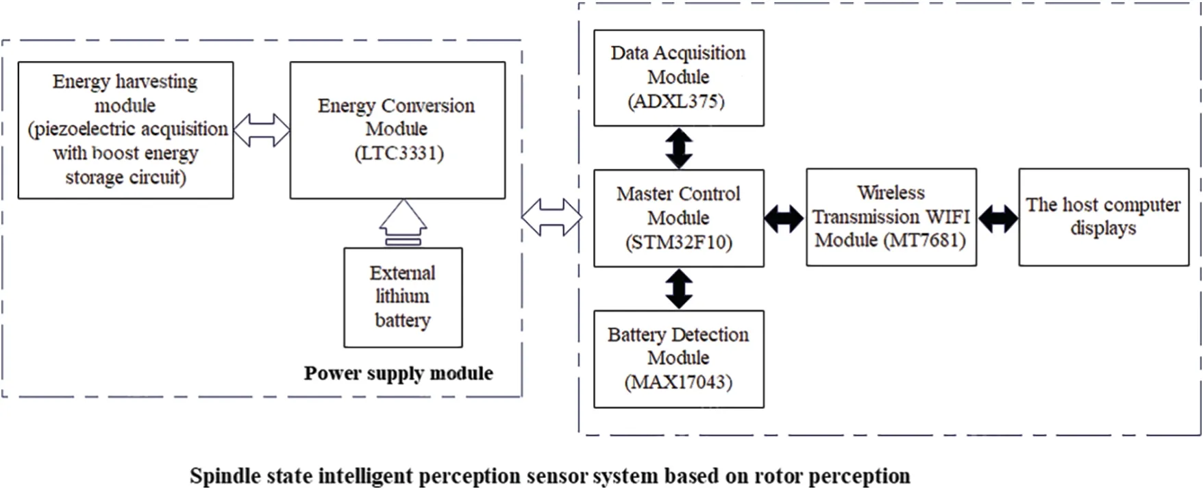
Figure 3: Overall structure design scheme
3 Hardware Integration Design of Piezoelectric Vibration Sensor
The hardware part of the wireless self-powered intelligent spindle vibration sensor system has built an integrated circuit that integrates energy supply, electric quantity monitoring, data acquisition and wireless transmission, which lays a foundation for the intelligent sensing sensor system to monitor the working status of the spindle.
3.1 Basic Principle and Design of Power Supply
3.1.1 Energy Harvester
When the machine tool is cutting the machined parts, it produces irregular vibration with uncertain direction.For the convenience of study, we simplify the vibration to tensile or compressive vibration.Firstly, the energy acquisition converter adopts piezoelectric devices, whose working principle is equivalent to piezoelectric effect.That is, the piezoelectric vibrator inside the piezoelectric energy acquisition converter will stretch or compress after being subjected to mechanical vibration, and a certain amount of positive and negative opposite charges will be generated on both sides of the piezoelectric material to form polarization.Charge can be drawn out through the electrode and collected and stored.
The piezoelectric vibrator is composed of a cantilever beam,a mass block and support.When the mass block vibrates, the piezoelectric vibrator transfers the external mechanical energy.The structure of piezoelectric vibrator and energy collector is shown in Fig.4.

Figure 4: Schematic diagram of piezoelectric vibrator of cantilever beam structure
The vibration modes of the piezoelectric vibrator can be divided into d31and d33.When the stress direction of the piezoelectric vibrator is parallel to the direction of the electric field, stretching vibration is generated, as shown in Fig.5.When the polarization direction of the piezoelectric vibrator is perpendicular to the direction of the electric field, shear vibration is generated, as shown in Fig.6.
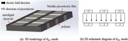
Figure 5: Working mode diagram of piezoelectric material d31 (polarization direction parallel to electric field direction)
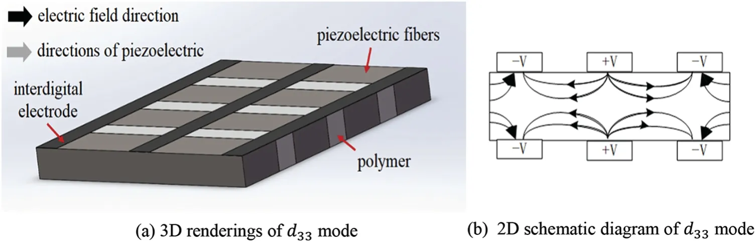
Figure 6: Working mode diagram of piezoelectric material d33 (polarization direction is perpendicular to electric field direction)
In the above two working modes, the formula for the output charge of open circuit voltage can be expressed as [24]:
In the formula,σ is the stress;g is the piezoelectric voltage coefficient;d is the piezoelectric coefficient;L is the interfinger electrode spacing;H is the piezoelectric layer thickness;A is the electrode area.
The relation between g and d is:
In the formula,ε is the dielectric constant.
Generally, the piezoelectric strain coefficient of d33is larger than that of d31, and the piezoelectric voltage coefficient of g33is also larger than that of g31.In comparison, d33mode outputs high voltage and low current, while d31mode outputs low voltage and high current.In order to satisfy the principle of low power consumption as much as possible, d31model is adopted in this paper.The selected piezoelectric material LDT0-028K is shown in Fig.7.
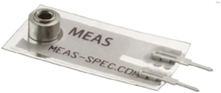
Figure 7: LdT0-028K physical picture
The LDT0-028K is a flexible component comprising a 28 μm thick piezoelectric PVDF polymer film with screen-printed Ag-ink electrodes, laminated to a 0.125 mm polyester substrate, and fitted with two crimped contacts.As the piezo film is displaced from the mechanical neutral axis, bending creates very high strain within the piezopolymer and therefore high voltages are generated.When the assembly is deflected by direct contact, the device acts as a flexible “switch”, and the generated output is sufficient to trigger MOSFET or CMOS stages directly.
3.1.2 Energy Management Module
The power module circuit is shown in Fig.8.P3 is the Li-ion battery or other mobile power interface;P4 is the piezoelectric energy harvesting interface.pin OUT2 is connected to Vin3,OUT1 and OUT0 pins are grounded,and it is known from the LTC3331 data sheet that when the OUT2,OUT1 and OUT0 logic output voltage is 1, 0 and 0, respectively, its output power supply Vout is 3.3 V; UV3, UV2, UV1, UV0 pins are connected to Vin2 pins, and the energy storage module uses 47 uF capacitors, which start discharging when the voltage across the capacitor reaches 18 V until the voltage drops to 5 V.

Figure 8: Energy management module circuit
In order to meet the supply demand of electricity to supply power to the whole system, the voltage conversion module converts the 5 V voltage into 3.3 V voltage to supply power to each module of the system.In addition,the LTC3331 piezoelectric vibration energy transducer is used to harvest the vibrational mechanical energy in the environment and convert it into electrical energy for storage on the storage capacitor battery pack of the LTC3331 module.Until the voltage across the capacitor battery circuit reaches the 18 V threshold, the energy conversion device begins to provide a stable 3.3 V output voltage for the subsequent circuits.When the vibration energy is insufficient, the capacitor battery pack supplies power to the system, and no longer discharges when the voltage across the capacitor battery pack drops to 5 V.At the same time, switch to an external lithium battery or other mobile power supply for supplementary power supply, and continue to provide a stable 3.3 V voltage for the system.This power supply not only prolongs battery life,but also prevents registers from losing data due to sudden power failure.
3.2 Design of Wireless Transmission for Vibration Data Acquisition
3.2.1 Energy Management Module
The main chip of the battery power monitoring module selects the MAX17043 produced by Maxim,and uses IIC communication to transmit power information.When it is detected that the power of the selfpowered module is lower than the power required for circuit operation, the signal light will flash to prompt,and the system will automatically switch to lithium battery power supply.
Compared with the traditional power monitoring method,the power monitoring module performs power measurement, which can save costs and reduce power consumption, and also has a programmable voltage alarm function,which can protect the circuit and reduce the experimental test deviation.
3.2.2 Data Acquisition
In the data acquisition part, the digital three-axis acceleration and vibration sensor ADXL375 module produced by a certain company is used.This system uses SPI communication mode for data transmission.
The ADXL375 has a supply voltage range of 2.0 to 3.6 V.When VS is applied,the device enters standby mode.In standby mode,power consumption is minimized to as low as 35 μA in measurement mode and 0.1 μA in standby mode(VS=2.5 V).In this paper,setting VDDI/O equal to VS,both at 3.3 V,allows to adapt to the required interface voltage, which requires a current of 1.6 mA.
Spindle processing speed should reach 0~4000 r/min.If the sensor range is too small,it cannot meet the high-speed requirement of the spindle.However,if the sensor range is too large,the detection accuracy will be affected.Therefore, the range of sensor system should be in the appropriate range.In this paper,ADXL375 sensor is selected,whose vibration range is ±200 g.
The relationship between acceleration and rotational speed is as follows:
According to the formula,the radius is proportional to the acceleration.The maximum theoretical speed is 2440 r/min when a sensor with a range of 200 g is installed on a tool handle with a diameter of 60 mm.Therefore,it can capture high-speed vibration signals and has sensitive vibration perception.
3.2.3 Wireless Transmission
Combined with the actual application requirements of the system on the machine tool spindle and the mature application of the current wireless WIFI communication technology, a company’s MT7681 module is used to realize the wireless WIFI transmission function.The system first realizes the serial communication between the main control unit and the wireless module.Then it performs parameter configuration and communication test through the serial port debugging module, and establishes the master-slave full-duplex communication mode between the hardware circuit board and the software host computer.Finally, the computer is connected to the configured wireless network, and the collected acceleration signals are sent to the upper computer.
The HLK-M35 and 2.4G’s on-board antenna are connected together as required by the IEEE 802.11 b/g/n standard.The working mode is set to A.P.mode,and the working voltage and input voltage are set to 3.3 V.The current required by the system is 75 mA,the startup time is 1 s,the 802.11 b/g/n protocol is perfectly supported,and the baud rate is set to 115200 bps.
3.3 PCB Circuit Design
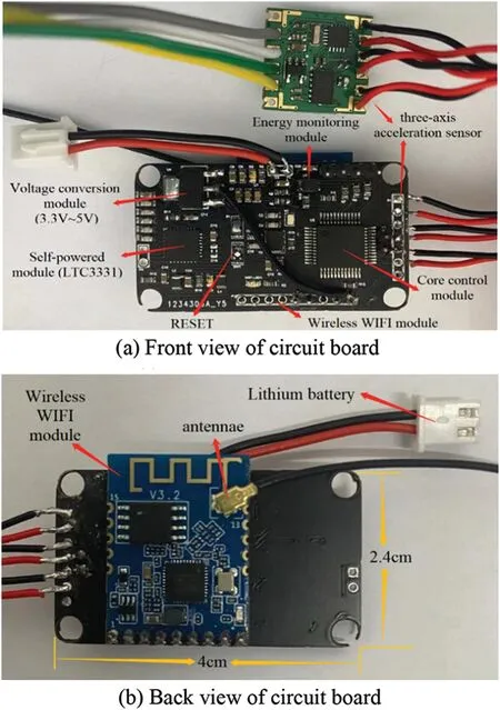
Figure 9: Working mode diagram of piezoelectric material d33 (polarization direction is perpendicular to electric field direction)
4 Hardware Integration Design of Piezoelectric Vibration Sensor
The system uses Keil MDK5 software for programming design,which is designed for microcontroller applications and has a perfect C/C++ development environment.It is programmed to achieve acceleration signal acquisition, wireless transmission, data communication and other functions.And the upper computer of the system is designed by LabVIEW programming.
4.1 Sensor System IIC and SPI Communication
The main control unit module drives the data acquisition module to sense and collect vibration signals,and then sends the data to the data cache area of the single chip microcomputer through SPI communication to wait for data transmission.
In addition, the electric quantity monitoring module and MCU are connected by IIC communication.After receiving the electric quantity feedback information from the electric quantity monitoring module,the SCM controls the LED light flashing to indicate that the electric quantity of the self-supply circuit is insufficient.IIC and SPI communication flow chart is shown in Fig.10.
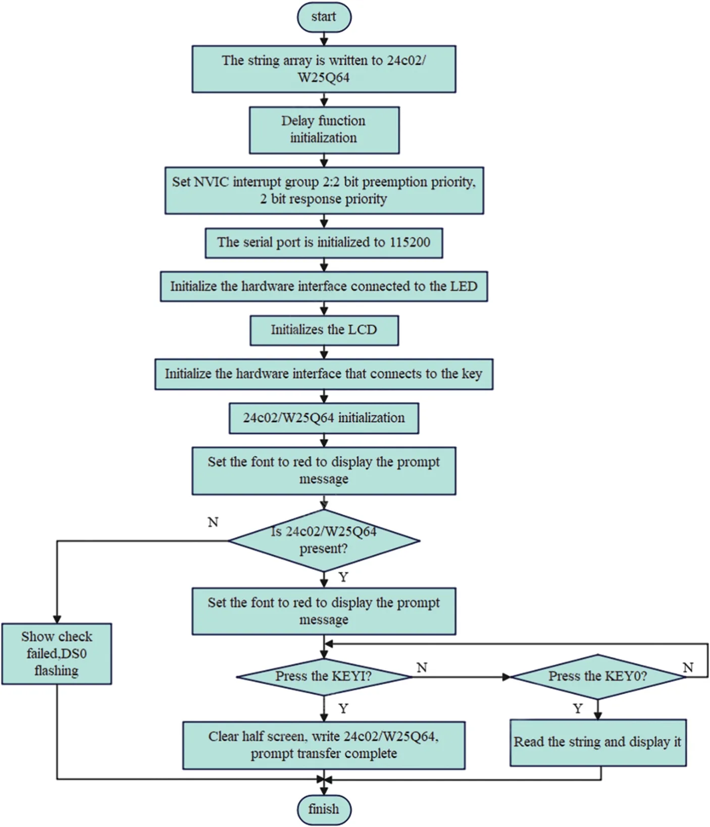
Figure 10: IIC/SPI communication flow chart
4.2 Serial Communication
Serial port communication is used to transmit signals between the wireless WIFI module and the main control single chip microcomputer.The MCU receives the data and prints the data to the computer through the serial port to realize serial communication.The flow chart is shown in Fig.11.
Figure 11: Serial port communication flow chart
4.3 LabVIEW P.C.
Wireless communication uses TCP/IP communication protocol.The port number,I.P.segment and I.P.address of the server and client corresponded one by one to realize the communication connection between the hardware circuit and the upper computer software.The upper computer transmits the data in the form of frame packets.At the same time,to make the data more reliable and not easy to lose,each frame packet is set with a specific identification frame header and packet number.After the data is packaged,the upper computer performs data analysis and other data processing for each frame, such as converting the data into sixteen mechanism or decimal display.When the data is parsed, the data is input into the display to output waveform.In order to better analyze the collected data, the upper machine has the function of saving data files.The software design process of the upper computer is shown in Fig.12.
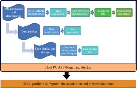
Figure 12: Upper computer software design flow chart
The interface of the upper computer system is shown in Fig.13,which includes four parts:file saving path area,start/stop area,data display area and waveform display area.Collect Data(16)refers to the hexadecimal data after the collected data is transmitted to the upper computer through wireless communication.The Data Frame Packet (16) is a data frame packet displayed in hexadecimal format.OutArray (10) is the decimal data of the high and low octets of the data in the Data Frame Packet (16).Three Channel Data (10) is the X,Y, and Z channel data in decimal format after data parsing.Substring(16) indicates the displayed packet group number in hexadecimal format.Number (10) is the decimal number of the packet group displayed in the output.Check whether the packet group number sequence is complete to effectively prevent packet loss.The four block diagrams in the lower left of the figure are three single-channel data waveform diagrams and waveform contrast diagrams of the acceleration sensor,respectively.
5 System Testing and Experimental Verification
In this paper,the sensor is installed on the machine tool equipment in the intelligent sensing high-end equipment laboratory to test the function of the piezoelectric self-powered wireless vibration sensor system.
5.1 Vibration Test of Energy Acquisition Module
The energy harvesting module is subjected to power supply detection.First,the wireless module and the three-axis acceleration acquisition module configured with parameters are connected to the circuit board.Then, the circuit board is inserted into the cylindrical sleeve.The sleeve structure shown in Fig.14.In order to realize the positioning and connection of the sleeve and the shank and ensure the monitoring accuracy, the inner and outer walls of the sleeve are respectively punched with a threaded hole and a square hole at a distance of 120 degrees, and the positions of the threaded hole and the square hole on the inner and outer walls are coincident.The energy harvester is attached to the tool holder to sense the vibration of the spindle under working conditions and collect vibration energy.It is connected to the AC1 and AC2 pins on the black circuit board through the square hole of the sleeve to ensure that the energy harvester, the spindle tool holder, the sleeve and the circuit board rotate at the same time.The vibration energy is collected by the energy harvester and converted into electrical energy by the LTC3331,which is stored in the capacitor battery pack located on the circuit board, thus ensuring that the energy is collected in the capacitor connected by many wires when the object rotates.When the sleeve is placed on the handle, a screw is added between the inner wall of the sleeve and the handle to increase stability.The sleeve with the sensor system is then mounted on the spindle shank.Due to the extremely high speed of the spindle during operation and the complex changes in the working conditions, the addition of one end of the sleeve to the sensing system will cause the rotor to be unbalanced.In order to improve this situation and keep the system stable, the other end (180 degrees) of the sleeve containing the sensing system is added with equal weight mass blocks for balancing.In addition, a mass block of equal mass is placed on the opposite side (180 degrees) of the card slot of the circuit board where the green acquisition module is installed for balance processing.When the part of Fig.15a is installed on the tool holder of the machine tool spindle, the center of gravity of the system is located at the center of the tool holder to improve the dynamic balance of the system and the accuracy of subsequent experiments.The physical map and overall installation view of the installation position of the development system in the sleeve are shown in Fig.15.A schematic diagram of the dynamic balance is shown in Fig.16.
No, replied the laborer. My wife died. Very gently, swaying with the motion of the train, the big man began to sob26. I don t got no wife, I don t got no home, I don t got no job. I m so ashamed of myself. Tears rolled down his cheeks, a spasm27 of despair rippled28 through his body.

Figure 13: LabVIEW upper computer system
The output of the controllable tip deflection applied to LDT0-028K was measured by using a charge amplifier to obtain the open-circuit voltage sensitivity.As shown in Fig.17, the deflection of 1.5 mm is sufficient to generate a voltage of about 5 V.It can be seen that the voltage generated by LDT0-028K is sufficient to support subsequent load circuits from 5 to 3.3 V.
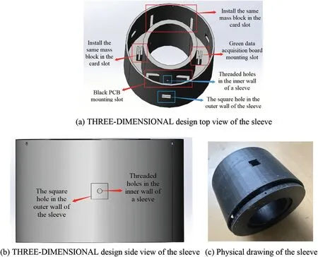
Figure 14: Power supply test of cylindrical sleeve and self-supply module
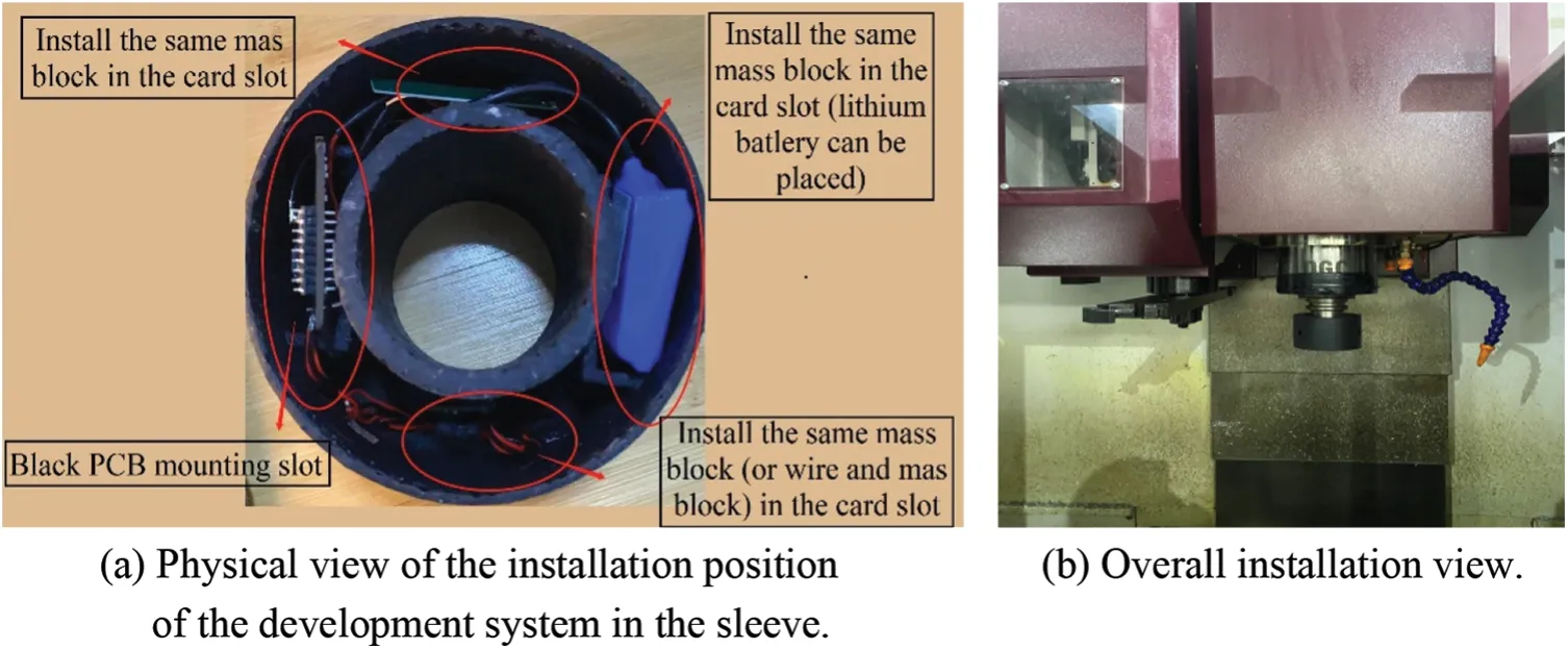
Figure 15: Physical drawing of sensor installation
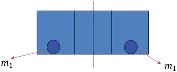
Figure 16: Dynamic balance diagram
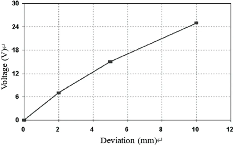
Figure 17: Relation diagram of tip deflection and voltage output
Start the machine and test the system.The circuit board test diagram is shown in Fig.18,in which D1 is the electric quantity indicator of the energy acquisition module.After the machine tool spindle runs for a period of time, the indicator D1 changes from off to dark to bright and continues to shine.After about 5 min of vibration charging, the indicator light D1 of the energy module glows for about 23 s.In the literature [25], the system is powered for 15 s after continuous vibration for 5 min.The experimental results of the system in this paper last for a longer period of time, which proves that the energy harvesting module can collect vibration energy, then the energy conversion module converts the vibration mechanical energy into electrical energy and stores it in the capacitor battery circuit.And the system can play a better role in energy storage and release,and realize the function of self-power supply.
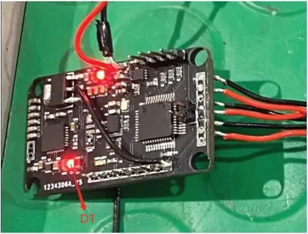
Figure 18: Circuit board test diagram
5.2 Vibration Signal Acquisition and Transmission Test and Verification
In the course of experimental testing, the LabVIEW-based wireless self-powered vibration sensor and APP-based rotor sensing high-precision sensor are installed on the Shenyang machine tool for experiment.And the collected data are uploaded to the top computer to draw the waveform diagram.The two waveforms were observed and the experimental data were compared.
The LabVIEW upper computer system displays the waveform of data obtained at 50 and 100 r/min speeds, as shown in Figs.19 and 20.The blue, yellow, and green curves in the figure are single-channel waveforms of X, Y, and Z, respectively.Waveform Chart represents the comparison diagram of threechannel waveforms in the same coordinate system.The abscissa is acquisition time (unit: s) and the ordinate is acceleration(unit:m/s2).
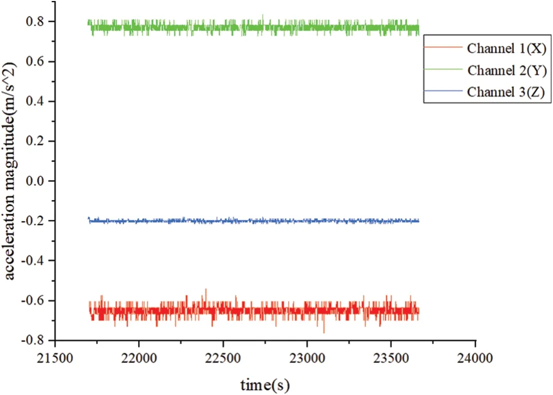
Figure 19: Waveform contrast diagram of three channels at 50 r/min speed
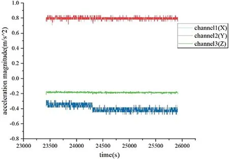
Figure 20: LabVIEW system interface at 100 r/min speed
The test results show that most of the collected X-axis data remain in the range of (-0.6~-0.7 m/s2),Y-axis data remain in the range of (0.73~0.81 m/s2), and Z-axis data remain in the range of(-0.185~-0.215 m/s2) at the spindle speed of 50 r/min.At the speed of 100 r/min, most of the collected X-axis data kept in the range of (-0.38~-0.45 m/s2), Y-axis data kept in the range of (0.76~0.84 m/s2),and Z-axis data kept in the range of (-0.175~-0.205 m/s2).By comparison, it can be concluded that the monitoring amplitude of the system basically remains between(-1~1 m/s2).
The field experiment of app-based rotor sensing sensor is shown in Fig.21, in which the output waveform of the wireless self-powered vibration sensor based on LabVIEW is shown in Fig.22.The vibration sensor system at the speed of 50 and 100 r/min was compared and verified by the three-channel waveform contrast diagram (as shown in Figs.19 and 20).According to the data analysis results obtained from the comparison experiment, the results of the wireless self-powered vibration sensor based on LabVIEW can be accurate to 0.1%, which is higher than the rotor sensing sensor based on APP.The collected data is more accurate after processing by the upper computer and has higher usability.
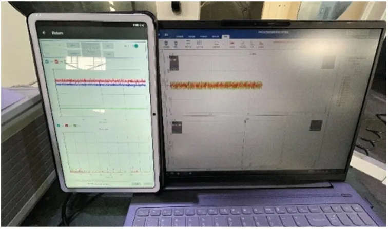
Figure 21: An APP field test picture
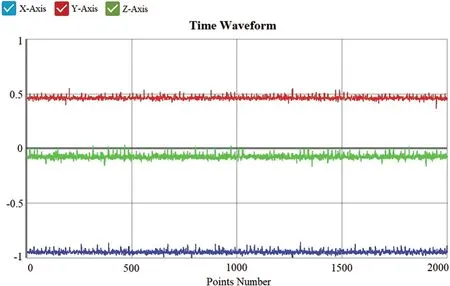
Figure 22: Test waveform of high precision acceleration sensor based on APP
5.3 Overall System Function Test at High Speed
When a part of mechanical equipment is worn or a part is damaged, its signal characteristics will be different from the signal under normal working condition.Therefore, the fault location can be located by feature extraction of vibration signals collected from faulty mechanical equipment and comparison with frequency components under normal working conditions.
In order to verify the applicability of the intelligent spindle piezoelectric self-powered wireless vibration sensor system in the equipment monitoring of the rotor system,the system was installed on the spindle handle of a CNC machine tool to monitor the working conditions of the spindle.
The workflow of system test is as follows:
S1:Starting up the machine to test the intelligent spindle piezoelectric self-powered wireless vibration sensor system.
S2:The piezoelectric transducer continuously converts vibration energy into electrical energy to power the system,and stores the excess energy in the energy storage capacitor battery.
S3:power detection module checks whether the voltage of the storage capacitor battery is greater than or equal to 10 v.If so, perform S4.If no,perform S2.
S4: The three-axis accelerometer continuously collects acceleration, and the wireless WIFI module sends the collected data to the upper computer for display.
S5:Stop the vibration energy and convert the power supply to the energy storage capacitor battery.At the same time,the power detection module determines whether the voltage of the energy storage capacitor battery is less than or equal to 5 V.If yes, perform S6.If no,perform S5.
S6: Lithium battery supplies power for system operation and continues S4.
S7: Turn off the power and turn off the machine.
According to the testing process, on the one hand, the energy acquisition module realizes energy acquisition and electric quantity conversion.On the other hand, the vibration acceleration signal collected by the three-axis acceleration sensor is sent to the main control chip through SPI communication, and then the WIFI module is controlled through serial communication for data transmission.WIFI module established network communication with LabVIEW host computer through TCP/IP network communication protocol.The circuit board integrated by each function module is equivalent to TCP server and LabVIEW host computer is equivalent to TCP client.When the port number specified on the client and server is the same, the two can communicate efficiently.
The function test experiment of piezoelectric self-powered wireless vibration sensor system on the spindle of machine tool is shown in Fig.23.
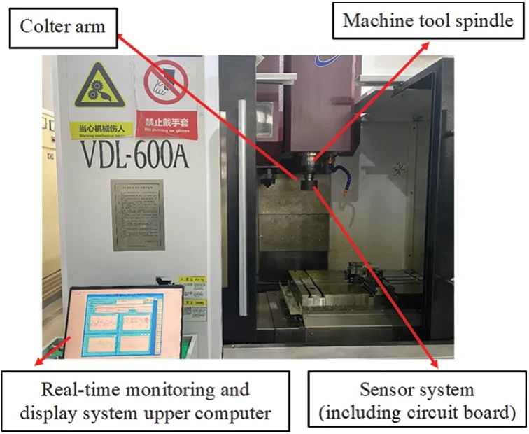
Figure 23: Diagram of vibration on-line monitoring system
When the wireless self-powered intelligent spindle vibration sensor system senses the external vibration,on the one hand,the energy collector begins to collect the mechanical energy in the environment and convert it into electrical energy.The power is stored in the energy storage circuit,and when it reaches the threshold of 18 V, it begins to power the subsequent circuit.And from the experimental results, it can be seen that the machine tool spindle runs in the idle working condition for about 15 h, and the mechanical energy converted into electric energy and the electric energy provided by the lithium battery can supply the system continuously for about 1 h, realizing the system self-power function.A comparison of the experimental data is shown in Table 1.
On the other hand,the sensor circuit collects vibration signals and wirelessly transmits them to the upper computer in the form of data packets (each 30 data is a frame packet, plus 8 data fixed frame headers and frame packet serial number, 38 data are a frame).The 30 numbers are output in the form of X, Y and Z channels and displayed in the waveform diagram.The spindle works at 1000 and 1500 r/min,respectively,and the waveform obtained is shown in Figs.24 and 25.
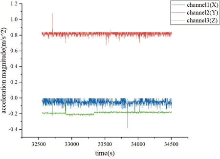
Figure 24: Waveform contrast diagram of three channels at 1000 r/min speed
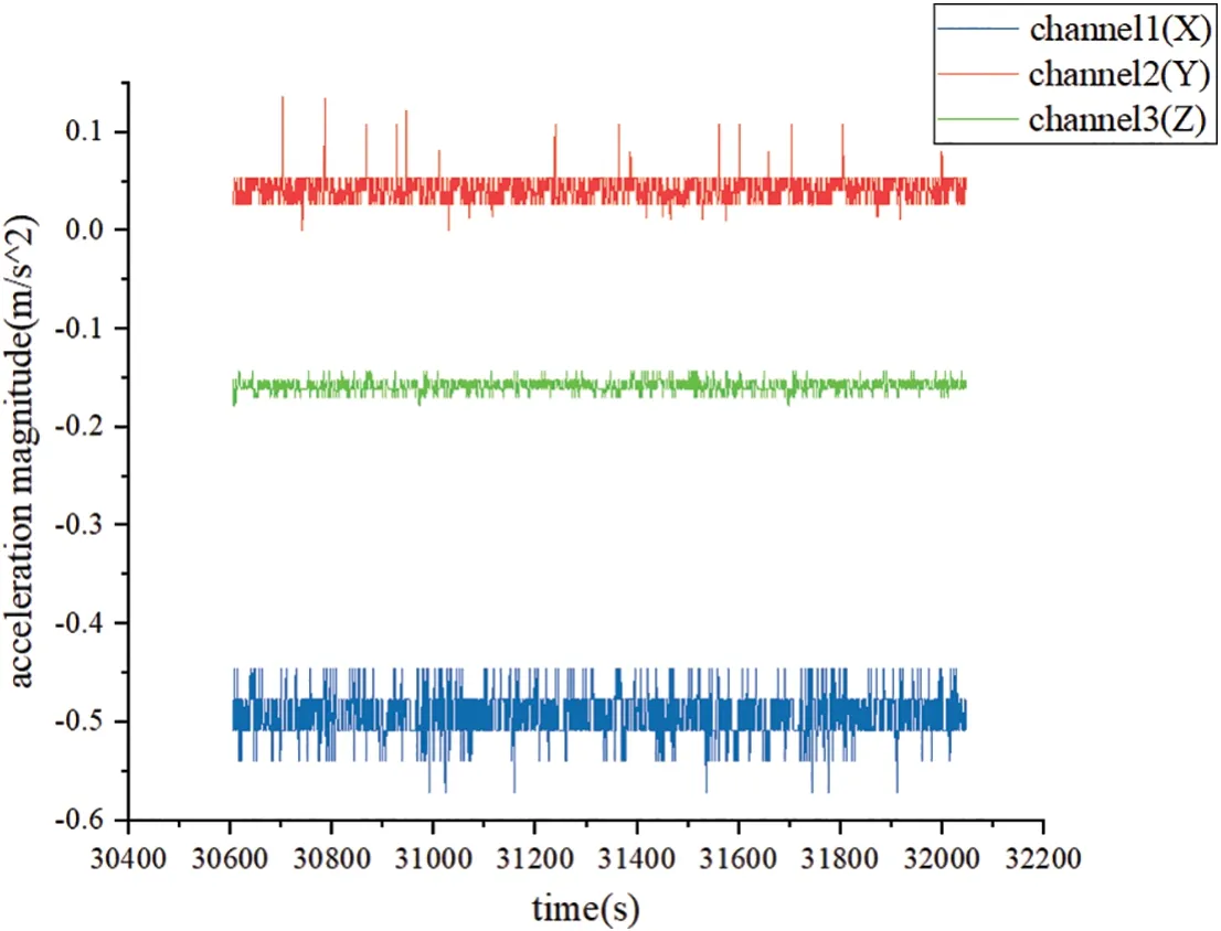
Figure 25: Waveform contrast diagram of three channels at 1500 r/min speed
The spindle of the machine tool will produce certain vibration in the process of working, which can provide energy source for the sensor system.When energy is insufficient, it will be supplemented by lithium battery.As can be seen from the figure, in the running process of the spindle, the sensor system can collect and transform the vibration signal of the spindle in real time and send the signal to the supreme machine through wireless WIFI to realize the real-time monitoring of the spindle state.
The test results show that the amplitude of acceleration data collected by the sensor system is stable in the range of(-1~1 m/s2)under the low speed of 500~1000 r/min.When the speed is higher than 1000 r/min,the amplitude of the data collected by the sensor system is basically stable between(-1~1 m/s2),but some impulse signals will be generated, which can be filtered later.The highest speed of the high-precision acceleration sensor based on APP can only reach 700 r/min, while the wireless self-powered vibration sensor based on LabVIEW can still accurately monitor the vibration state of the spindle at 1500 r/min,which can achieve vibration monitoring at a higher speed.
6 Conclusion
In this paper,aiming at the requirements of state monitoring,fault diagnosis and energy self-supply of machine tool spindles under different working conditions in the manufacturing industry, the experimental verification of wireless self-powered intelligent spindle vibration sensor system based on STM32 is realized.The system is integrated with power module and signal acquisition and transmission module.The power module implements self-power supply for subsequent circuits through the energy collection module and energy management module, and is supplemented by the lithium battery.The electric quantity monitoring module is used to monitor the electric quantity in real time.The signal acquisition and transmission module realizes the vibration signal acquisition, processing and wireless communication transmission under the working conditions of the spindle, and uses LabVIEW software to complete the design of the upper computer.The analytic vibration data is displayed on the interface of upper computer,which is ready for feature extraction and fault diagnosis.Considering the working conditions and requirements of the processing site, the design of sensor packaging, sleeve and protective cover is completed.Experimental results show that the microsystem has small volume, low power consumption,high precision and significantly improved energy utilization rate, which provides technical support for online monitoring of machine tool spindle status and self-power supply of intelligent sensing system.
Funding Statement:This work was supported by the National Natural Science Foundation of China(51975058).
Conflicts of Interest:The authors declare that they have no conflicts of interest to report regarding the present study.
 Structural Durability&Health Monitoiing2023年4期
- Structural Durability&Health Monitoiing的其它文章
- Research on Breeze Vibration Law and Modal Identification Method of Conductor Considering Anti-Vibration Hammer Damage
- Weak Fault Detection of Rotor Winding Inter-Turn Short Circuit in Excitation System Based on Residual Interval Observer
- Speed Measurement Feasibility by Eddy Current Effect in the High-Speed MFL Testing
- Development of Features for Early Detection of Defects and Assessment of Bridge Decks