
Electro-hydraulic servo force loading control based on improved nonlinear active disturbance rejection control
2024-01-08 09:11LIXiaoyuanGULichenGENGBaolongCHENGDonghongZHANGBenben
LI Xiaoyuan,GU Lichen,GENG Baolong,CHENG Donghong,ZHANG Benben
(School of Mechanical and Electrical Engineering,Xi’an University of Architecture and Technology,Xi’an 710055,China)
Abstract:The transient and dynamic loading accuracy of the valve controlled cylinder force loading system of the undercarriage actuator cylinder wear and life experiment platform is low,which cannot meet the accuracy requirements of the load spectrum,thus affecting the safety and reliability judgment of the actuator.An improved nonlinear active disturbance rejection control (INADRC) algorithm with higher accuracy and anti-interference ability is proposed based on control algorithm.First,the AMESim/Simulink co-simulation model of the electro-hydraulic servo force loading system is established.Secondly,in order to optimize its parameters,the INADRC controller is designed,and the genetic particle swarm algorithm is used.Finally,the performance of the controller is verified by simulating and experiment with three target signal tracking.The simulation and experimental results show that compared with PID control,nonlinear ADRC (NADRC) and other improved nonlinear ADRC (ONADRC),the average accuracy of the INADRC is improved by 4.15%,1.15% and 0.65%,which reflects the characteristics of high servo force transient,dynamic loading accuracy and strong anti-interference ability.
Key words:undercarriage actuator cylinder; valve-controlled cylinder system; nonlinear active disturbance rejection control; genetic particle swarm optimization; electro-hydraulic servo force loading control
0 Introduction
Aircraft undercarriage system is one of the key systems of aircraft.Many accidents caused by landing gear system failure are fatal,such as failure of the landing gear actuator,the landing gear cannot be put down,and so on.Therefore,the reliability and safety of the aircraft landing gear actuator is essential.The key to judge the reliability and safety of the actuator is to carry out the electro-hydraulic servo force loading experiment.
Electro-hydraulic servo system is a typical non-linear system.The parameters of the system are time-varying and uncertain.With the change of working conditions,the internal and external leakage and other external interference make the dynamic characteristics of the system more complex[1].The time-varying and nonlinear characteristics of the loading system must be considered to ensure the control accuracy and repeatability of the loading process.Although the traditional control algorithms such as PID and fuzzy control can basically meet the output requirements of the loading system,the accuracy,rapidity,and even stability of some nonlinear and time-varying control scenarios will be degraded to varying degrees.It is difficult to achieve the expected control effect.For example,in order to control the loading accuracy of the landing gear actuator life experiment platform to meet the requirements,it must be considered that the performance and operating parameters of the loading system components will change in varying degrees with the fatigue loading process of the system,and the unreasonable control parameters will lead to the decline of the control accuracy of the system.
How to obtain better control quality has been extensively and deeply carried out.The controller of the loading system was designed based on the quantitative feedback theory (QFT),which solved the nonlinear problem caused by the rotation disturbance of the industrial CT hydraulic system,improved the dynamic characteristics of the system,and made it meet the requirements of dynamic loading of the rock samples[2].Several improved PID algorithms were tested[3].The results showed that the integral separation nonlinear PID controller could make the system response fast and there was no overshoot.Sliding mode control was introduced into the backstepping controller,which reduced the interference sensitivity of the system and improved the anti-interference tracking performance of the electro-hydraulic servo system[4].A control strategy combining feedforward inverse model with robust control was proposed,which improved the tracking performance of force control in flight simulator[5].A nonlinear robust double closed-loop control strategy was developed,which effectively suppressed the nonlinear and friction factors in the process of hydraulic cylinder movement,and improved the quality of system force control[6].A motion synchronization compound decoupling method was proposed to realize the multi-channel force control of the aircraft structural load testing machine[7].
These methods have achieved good control effect,but they rely too much on the system model or need much model information.In 1998,Han Jingqing proposed the active disturbance rejection control (ADRC) without precise model.In 2003,Gao Zhiqiang simplified the nonlinear ADRC (NADRC) to the linear ADRC (LADRC),which promoted the engineering application and popularization of ADRC.At present,the deficiency of regulation ability has been exposed in some occasions for LADRC such as large time-delay system.LADRC can almost be regarded as a special case of NADRC.Therefore,NADRC has more freedom and possibility than LADRC,so it must also have better adaptability[8].
In recent years,the application of NADRC has developed rapidly.Sun Bin applied NADRC system to permanent magnet motor speed regulation system,which effectively improved the anti-interference ability and tracking accuracy of the system and had good dynamic and static characteristics[9].Wang Gaolin applied NADRC controller to the direct drive permanent magnet traction system[10].The experiment showed that it could effectively reduce the reverse slip distance and speed in the starting process of elevator.Yao Fang designed the electric vehicle electronic parking NADRC controller,which was verified that the designed control scheme had strong robustness to internal and external disturbances in the parking process,and could realize fast and effective braking in the parking process[11].Shi Jia applied the designed NADRC control algorithm to the four rotor UAV and achieved good control results in the flight test with large eccentric load and strong interference with uncertain direction[12].
According to the working load characteristics of the landing gear actuator,a new type offalfunction is used to construct an improved nonlinear extended state observer (INESO) for real-time state estimation and external disturbance rejection compensation of the actuator experiment platform loading system,which overcomes the time-varying and nonlinear characteristics of the electro-hydraulic loading system.The tracking control of high precision electro-hydraulic servo force loading system is realized.
1 Design of INADRC controller
The basic structure of INADRC is shown in Fig.1.INESO is used to estimate the state and disturbance information of the system in real time for INADRC.Nonlinear state error feedback (NLSEF) is used to realize the state feedback of nonlinear state and disturbance,so as to restore the controlled object full of disturbance,uncertainty and nonlinearity to the standard integral series type.The active disturbance suppression and reduction are realized.
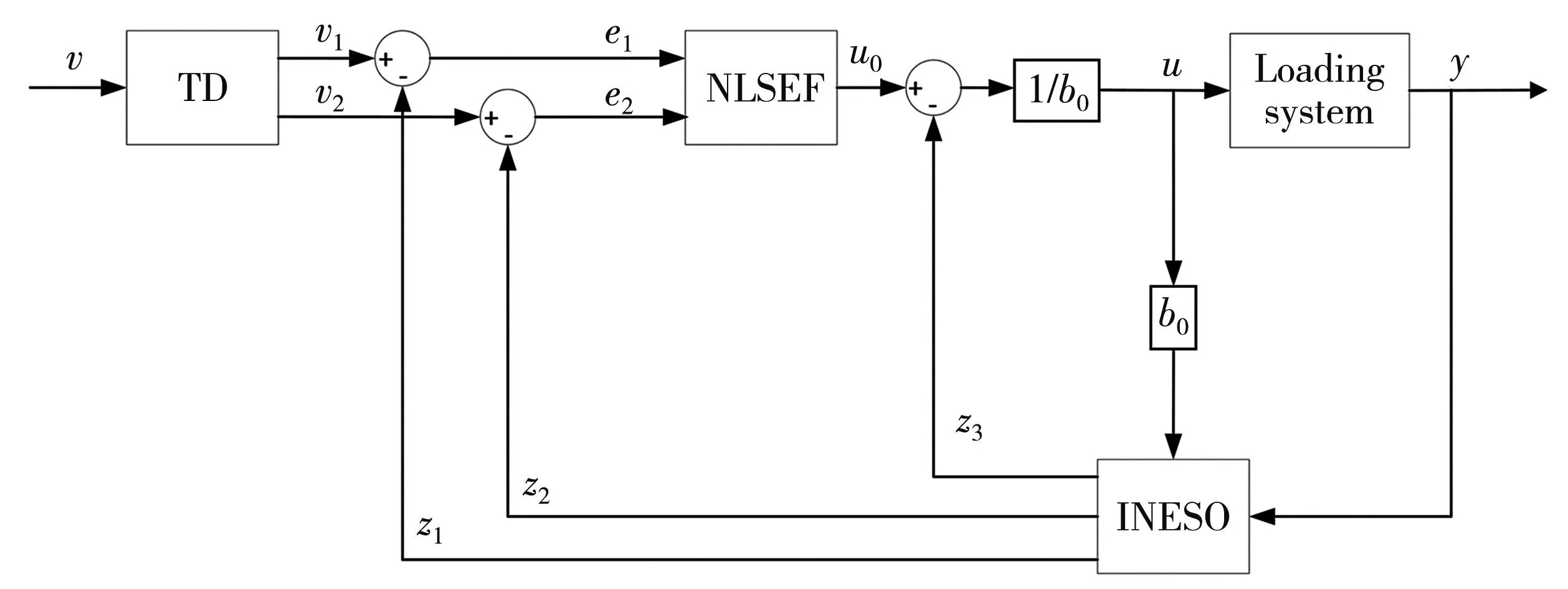
Fig.1 Basic structure of INADRC
1.1 Improved nonlinear extended state observer
INESO is the core part of INADRC,which is used to solve the core problem of disturbance observation in active disturbance rejection technology.The basic idea is to expand the total disturbance into a new state variable of the system,and then use the input and output of the system to reconstruct all the states including the original state variable and disturbance of the system.The INESO does not depend on the model that generates the disturbance,nor does it need direct measurement to observe the disturbance and get the estimated value.
1.1.1 Newfalfunction
The traditionalfalfunction is shown in Eq.(1).The second linear term is slower than the first nonlinear term near the origin.It also shows that the nonlinear term can better achieve “small error amplification” in this interval.In the interval far from the origin,the linear term converges faster than the nonlinear term.As a whole,it shows that there is room for improvement in the convergence performance of the traditionalfalfunction[13].
(1)
The new type offalfunction is shown in Eq.(2),and satisfies the properties 1) and 2).
(2)

1.1.2 Improved nonlinear extended state observer
The discrete form of the INESO is shown in Eq.(3),and satisfies the properties 1)-3).

2) If 0<β1<β2<β3<1,λ1>0,λ2>0,λ3>0 and other parameters are the same,the NESO ofC(ε1,β1) is faster than the NESO ofC(ε1,β2).
3)C(ε,β) instead offal(s,β,δ) does not change the stability and convergence of NESO and speeds up the convergence of NESO.
(3)
whereλ1,λ2,λ3are determined by the sampling step of the system,and they can be the same;b1is approximately equal tob0.
1.2 Tracking differentiator
Tracking differentiator (TD) is used to solve the problem of reasonable extraction of the continuous signals and the differential signals from discontinuous or random noise measurement signals to improve control quality and simplify controller design.It is shown as
(4)
whereris the control gain determined by the transition process;h0is an integer multiple of the sampling periodh.
1.3 Nonlinear state error feedback
The specific form offhanis shown as Eq.(5).The three signals of error,error differential,and error integral generated by TD are combined to form NLSEF,in the form of Eq.(6).
(5)
(6)
wherecis the damping factor;h1is the precision factor.
1.4 Disturbance compensation
Disturbance compensation forms the control quantity,shown as
(7)
whereb0is the compensation factor.
2 INADRC controller parameter setting
There are as many as 12 control parameters in the general form of INADRC,and as many as 8 even after being simplified.The current parameter setting mainly includes the empirical trial and error method and the artificial intelligence method.The ordinary empirical trial and error method is complex,time-consuming,laborious and subjective.It is difficult to guarantee its control accuracy and system stability.Therefore,the artificial intelligence method has a huge advantage in parameter tuning.The genetic algorithm particle swarm optimization (GAPSO) will be used to optimizea,b,β,h0,c,r,h1,b0in the controller.
2.1 Genetic particle swarm algorithm
Particles warm optimization (PSO) is widely used in fields such as multi-objective function optimization,system configuration,transportation and water conservancy systems because of its simple program and easy implementation.Each particle in the algorithm is a set of solutions.Through comparison among the particles,the fitness value is used to judge the pros and cons of the particles.First,a particle swarm is randomly generated in the feasible solution space,and each particle represents a feasible solution.The particle characteristics are represented by position,speed and fitness value.During the operation of the algorithm,the particles continuously move to the optimal position,that is the optimal position of the fitness value.During the iteration process,the particles update its speed and position through
(8)
(9)
wherekis the current iteration number;ωis the inertia weight;c1andc2are acceleration factors;r1andr2are random numbers between[0,1];vidis the particle’sd-th dimensional velocity,which is in the interval[vmin,vmax];Xidis thed-th dimensional position of the particle,which is in the interval[Ld,Ud];Pidis the position of the individual extreme value; andPgdis the position of the group extreme value.
The particle swarm algorithm updates the position of the particles by tracking the extreme value,but the particles tend to be similar in the process of continuous iteration,which is easy to fall into the local optimum.In order to improve the traditional particle swarm algorithm,the crossover and mutation operations of the genetic algorithm are introduced into the particle swarm algorithm to form the GAPSO.In GAPSO,the fitness value of all particles is first calculated,and all particles are sorted according to their fitness value.After the sorting is completed,the particles whose fitness value is worse than the average fitness value of the particles are discarded.Then the crossover operation is performed.The remaining particles with better fitness are randomly crossed with the individual extreme value or the group extreme value to obtain new particles,until the size of the particle swarm is restored to the original number.The position of the new particle can be obtained by[14]
(10)
(11)
whereYtdis the position of the new particle generated by the crossover operation; andr3is a random number between[0,1].
The mutation operation mutates the particle itself,and the better the fitness value of the particle,the smaller the probability of mutation.Assign a random number within[0,1]to the positions of all particles in each dimension.When the random number corresponding to thed-dimensional positionXidof the particle is less than the mutation probability value corresponding to the particle,the mutation operation ofXidis performed by
(12)
Integral of time multiplied by the absolute value of error (ITAE) is selected to calculate the fitness value of particles,and its definition is

(13)
wheree(t) is the error signal.
The main parameters of GAPSO are shown in Table 1.
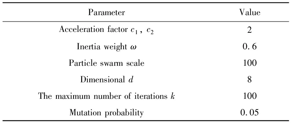
Table 1 GAPSO parameters
2.2 GAPSO realization process
The implementation process of GAPSO is as follows,and the flowchart is shown in Fig.2.
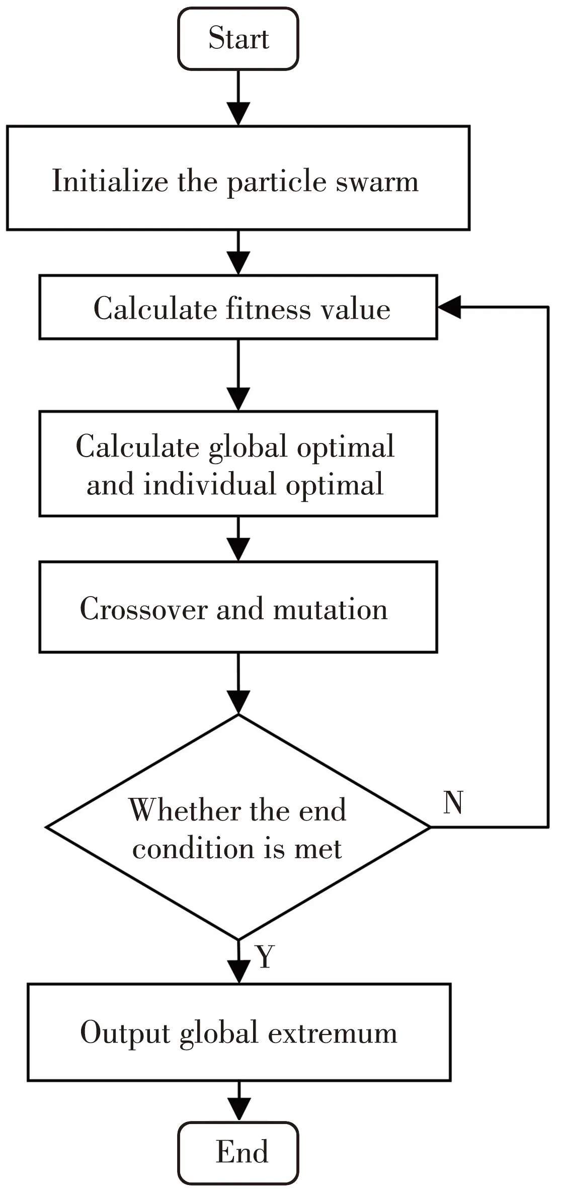
Fig.2 GAPSO algorithm flow
1) Initialize the particle swarm.Determine the size of the particle swarm,the upper and lower limits of the particle position interval,the maximum number of iterations,and the minimum fitness value,etc.
2) Calculate the fitness value of all particles.
3) Compare the fitness value of each particle with the fitness value corresponding to the optimal position that the particle itself has experienced.If it is better,the current position of the particle is set to the new individual extreme value.If the optimal fitness value of the particle swarm is better than the fitness value corresponding to the population extremum,the particle position corresponding to the optimal fitness value is set as the new population extremum.
4) Perform crossover and mutation operations on particle swarms
5) If the current iteration number exceeds the set maximum iteration number,or the population optimal particle fitness value is less than the minimum fitness value,the algorithm ends,otherwise,it returns to step 2).
3 Simulation
In the design of the electro-hydraulic servo force loading system,in order to clarify the static and dynamic characteristics of the system,the computer simulation technology can be used to establish the model of the electro-hydraulic servo force loading system and design the control algorithm.AMESim provides a set of electro-hydraulic servo simulation modeling and analysis solutions,which can be connected with Simulink.Establishing a AMESim/Simulink co-simulation model can give full play to the modeling capabilities of AMESim and the algorithmic computing capabilities of Simulink[15].
3.1 Establish co-simulation model
In order to study the loading performance of the system,the method of simulating loading by the proportional relief valve has been widely applied to the hydraulic experiment platform[17].The schematic diagram of servo force loading is shown in Fig.3.It is composed of a three-phase motor,a gear pump,a proportional directional valve,a proportional relief valve,a single rod double-acting hydraulic cylinder,and a tension pressure sensor.
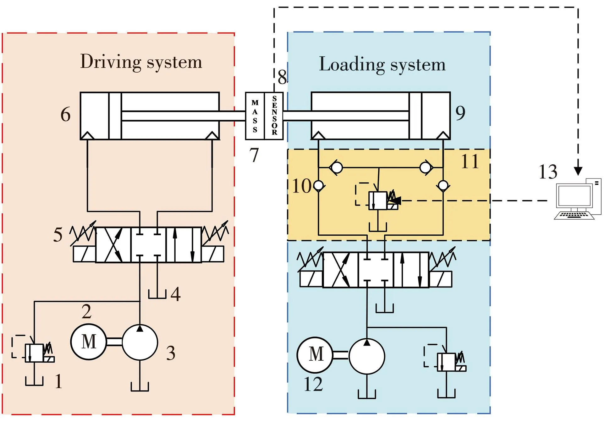
1-Proportional relief valve; 2-PMSM; 3-Gear pump; 4-Tank; 5-Proportional directional valve; 6-Driving cylinder; 7-Mass; 8-Force sensor; 9-Loading cylinder; 10-Check valve; 11-Backpressure loading valve group; 12-Three-phase induction motor; 13-Control system
The drive system is used to move the undercarriage actuator,the motor speed is 1 500 r/min,and the gear pump displacement is 6.3 mL/r.The loading system is used to simulate the wind load and external interference experienced when the landing gear actuator cylinder moves.The motor speed is 1 000 r/min,and the gear pump displacement is 4.3 mL/r.The AMESim simulation model of the hydraulic system is shown in Fig.4 which restores the working scene established by the valve-controlled cylinder system of the experiment platform.The simulation parameters are shown in Table 2,and the Simulink controller model is shown in Fig.5.
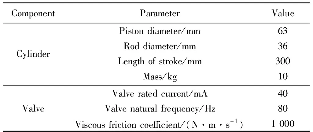
Table 2 Experiment platform parameter
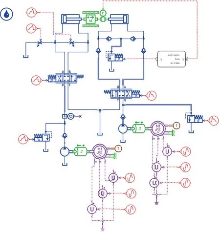
Fig.4 AMESim model
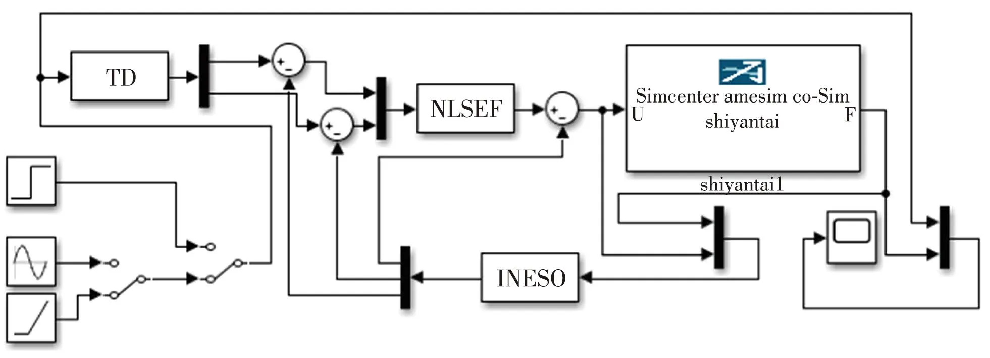
Fig.5 Simulink controller model
3.2 Simulation results
The main parameters of INADRC after GAPSO algorithm optimization are shown in Table 3.In order to verify the dynamic and static characteristics of INADRC controller optimized by GAPSO algorithm applied to electro-hydraulic servo force loading system,INADRC is compared with NADRC,PID and other improved NADRC (ONADRC),which forms such as Eq.(14)[13].The system constant signal,ramp signal,and sine signal are given.The simulation time is 10 s,and the step length is 0.01 s to run the AMESim/Simulink co-simulation model.The hydraulic cylinder force tracking curve and tracking error curve are obtained as shown in Fig.6.
(14)
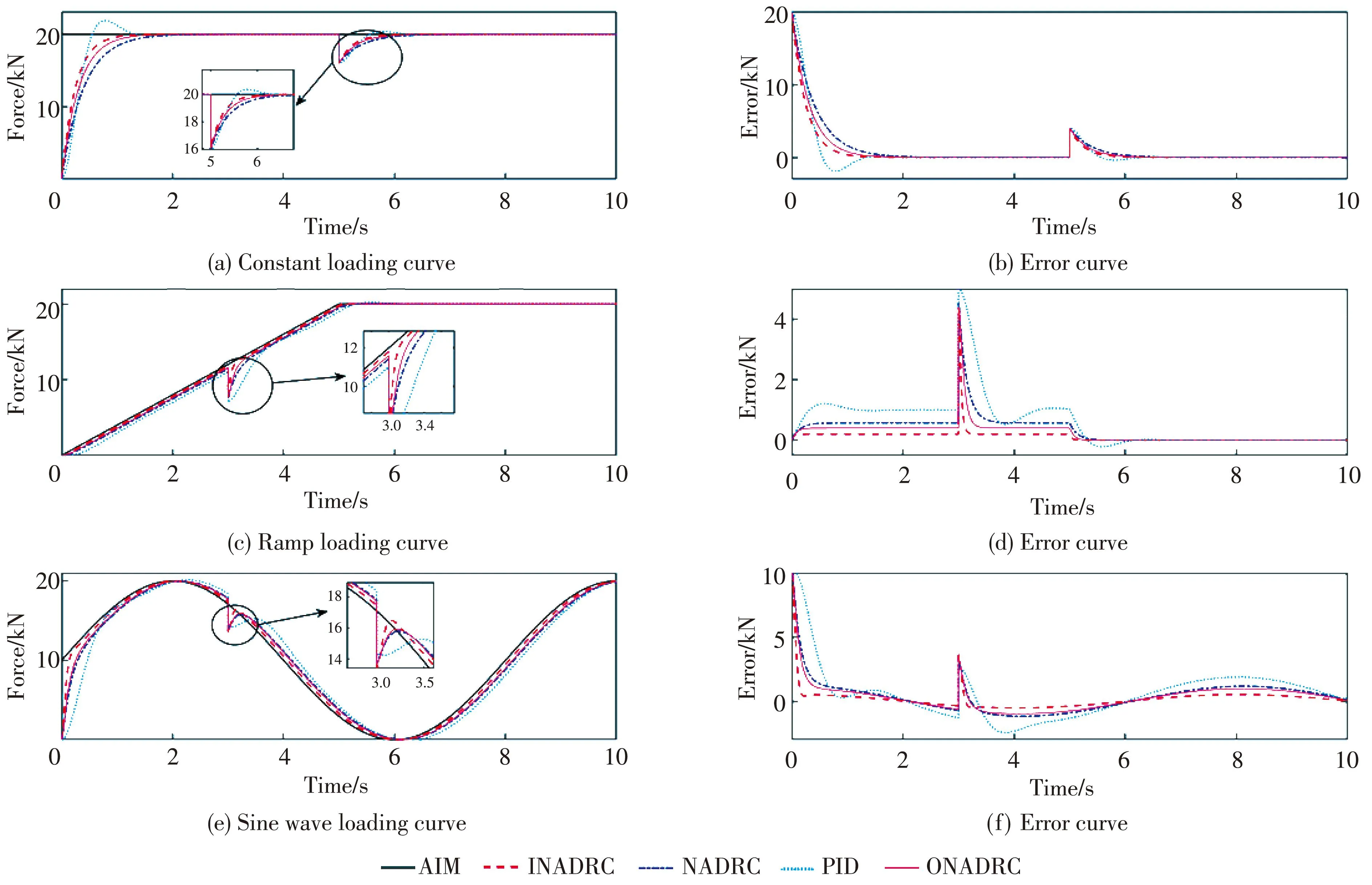
Fig.6 Simulation results
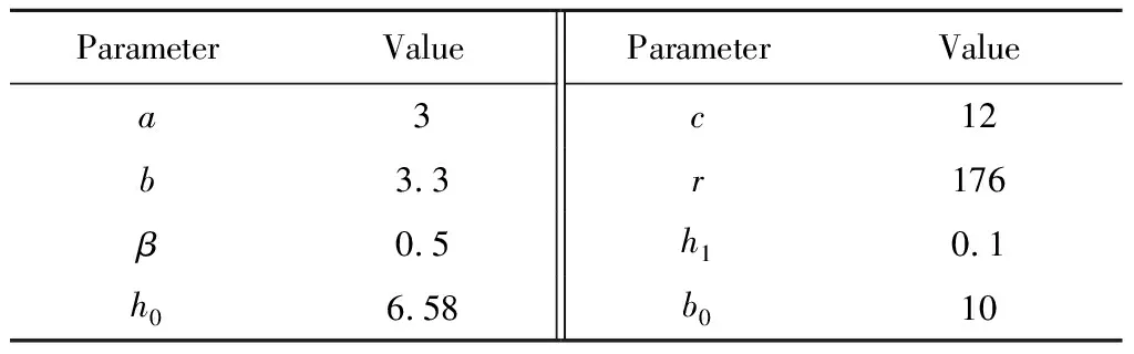
Table 3 INADRC controller parameter
1) Constant loading.The transient performance of the system is tested by constant load[16].Given a target force signal of 20 kN,the interference force is 4 kN in 5 s,and the force tracking and error curves are shown in Fig.6(a) and 6(b).In terms of transient response,the transition times of INADRC,NADRC,PID,and ONADRC are 1.5 s,2 s,2 s,and 1.7 s,respectively,and only PID has 2 kN overshoot.In terms of anti-interference ability,the time taken for the four control modes to recover to the steady state is 1 s,1.2 s,1.2 s,and 1.1 s,respectively.It can be seen that the comprehensive performance of INADRC in transient response and anti-interference ability is better than other control methods.
2) Ramp loading.Ramp loading is the most commonly used loading method for material testing machines and universal loading testing machines,which can verify the precise tracking ability of the controller.Set a ramp loading signal with a slope of 4 kN/s,and an interference force of 4 kN at 3 s.The resulting tracking and error curves are shown in Fig.6(c) and 6(d).Simulation results show that the performance of the four control algorithms is close,but it can be seen more clearly from the error curve that the tracking performance of INADRC is better.
3) Sine wave loading.The sine wave loading can verify the dynamic performance of the controller.Given the target force signalF=10sin(0.2πt)+10,the interference force is 4 kN at 3 s,and the force tracking and error curves are shown in Fig.6(e) and 6(f).The simulation results show that the fastest response of INADRC is to track the sinusoidal loading curve in 0.2 s,and the error is always within 0.3 kN.In case of interference,the tracking target signal can be recovered faster.
4 Experimental verification
4.1 Experiment platform
Fig.7 shows the electro-hydraulic servo force loading system experiment platform,which can be used to test and verify the proposed force loading control method.
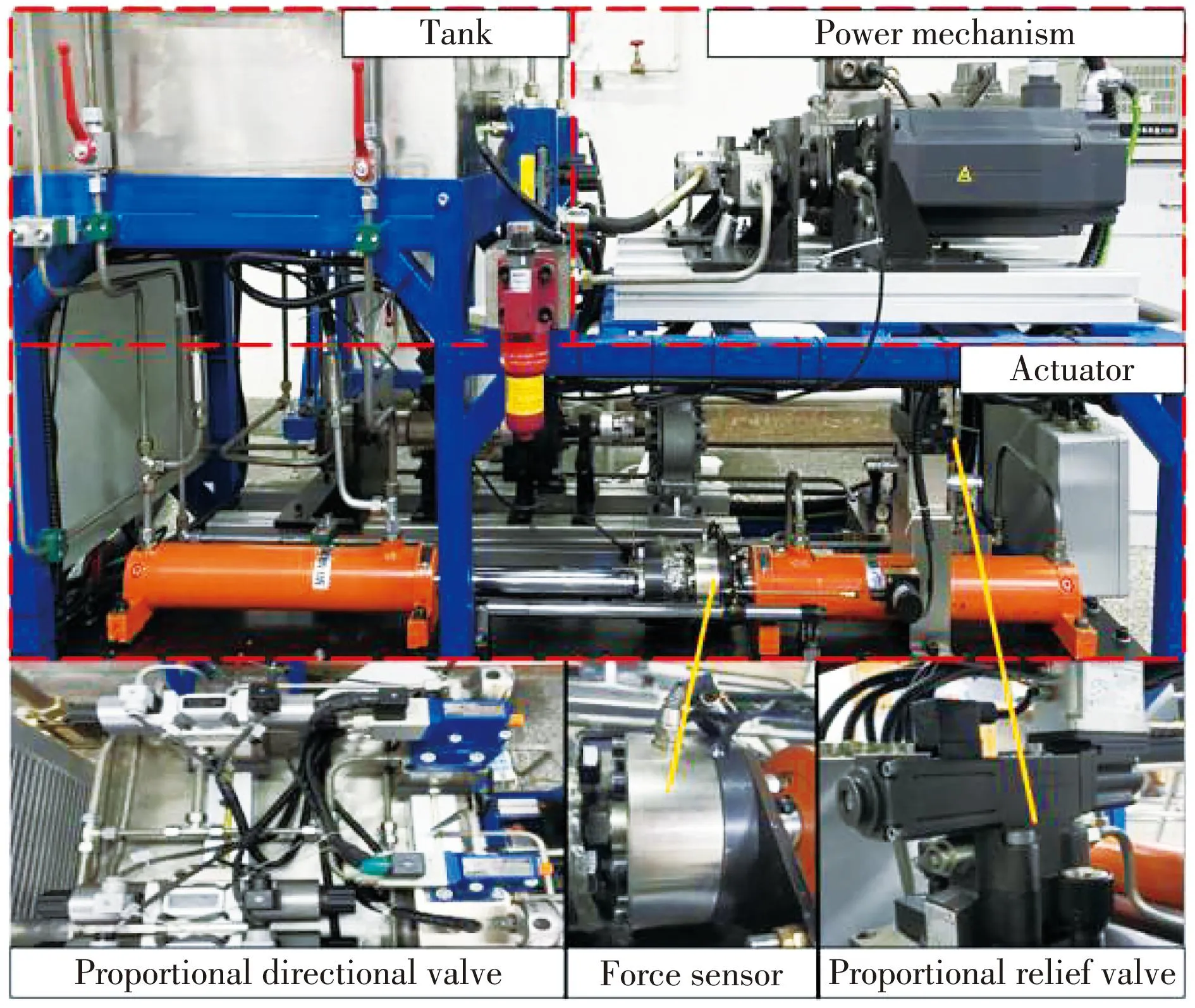
Fig.7 Experiment platform
The driving part adopts GK6087-6AF61-2 PMSM with a speed of 1 500 r/min and a PG502A0043CH1 gear pump with a displacement of 6.3 mL/r.The reciprocating movement of the hydraulic cylinder is controlled by a proportional directional valve to simulate the expansion and contraction of the landing gear actuator cylinder.PMSM and proportional directional valve realize drive function.The loading part adopts YYF2-112M-4 three-phase asynchronous motor with the speed of 1 000 r/min and PG502A0043CH1 gear pump with the speed of 4.3 mL/r.
Servo force loading function is achieved by controlling the rated pressure of the AGMZO-TERS-PS-10/315/Y proportional relief valve.Because the back pressure loading system oil is composed of 4 check valves and a proportional relief valve,there will be oil shortage after the loading cylinder moves,so the motor,gear pump and proportional reversing valve in the loading system realize the hydraulic cylinder replenishment function.
Two UG21D63/36-300TYCR single-rod double-acting hydraulic cylinders of the same specification are installed on the same straight line in the experiment platform,and connect with mass block and PLD204A2 5T force sensor,which can collect the feedback force loading value in the loading system in real time.The parameters of the experiment platform are shown in Table 2.
4.2 Measurement and control system
Fig.8 shows that the control scheme of the electro-hydraulic servo force loading system experiment platform.The hardware of the control system mainly includes the WANDFLUH SD7 controller,the A/D board PCI1715U,the D/A board PCI1723 and the control host and so on.
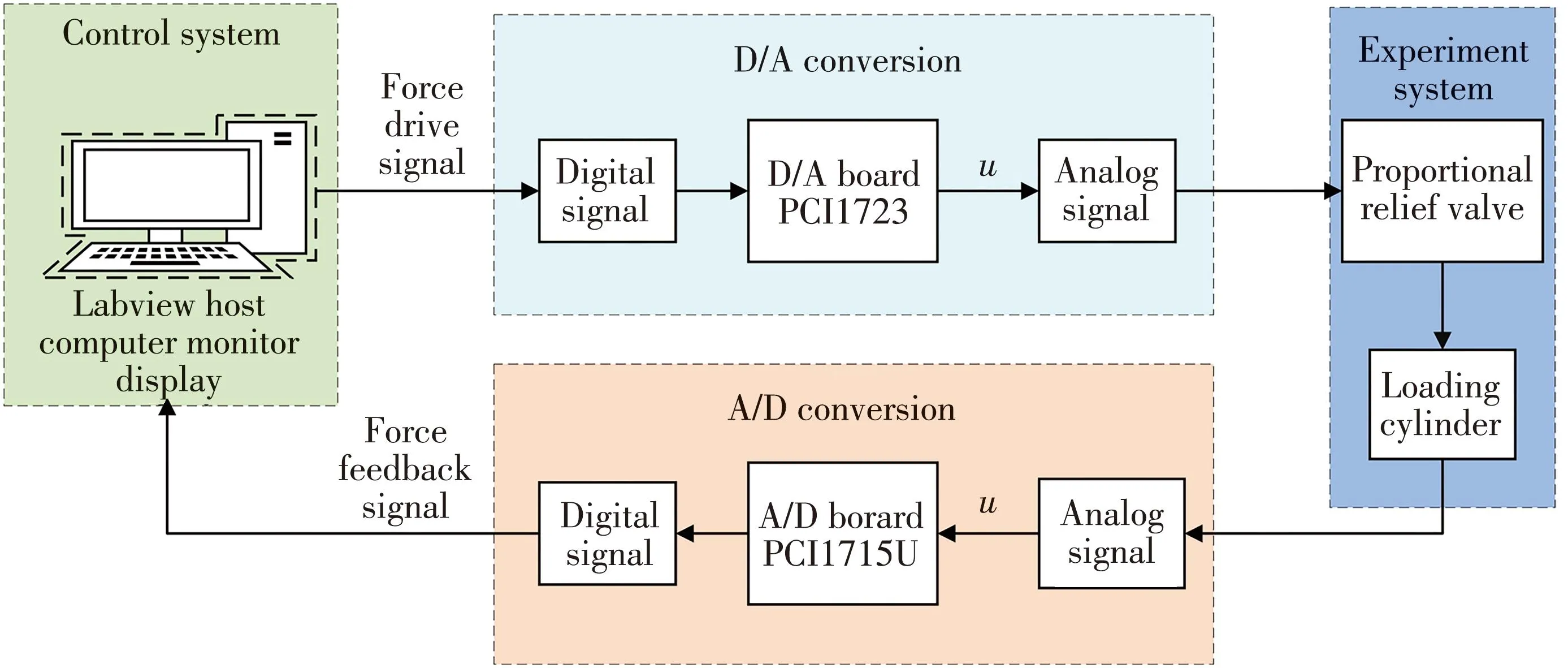
Fig.8 Schematic diagram of measurement and control
Among them,the D/A board converts the digital control signal into an analog output signal,and then sends it to the proportional relief valve as a control signal to control the action of the hydraulic cylinder.The A/D conversion board converts the collected analog signals such as force,acceleration and displacement into digital signals and inputs them to the host,so as to perform mathematical operations through the control algorithm module in the lower computer[18-19].
4.3 Experimental results
Set the system pressure to 10 MPa and the ambient temperature to 27 ℃.The range of force sensor is 0 kN-50 kN,and the feedback electric signal is 0 V-10 V.Other working conditions are consistent with simulation working conditions,and the experimental parameters are shown in Table 2.
It can be seen from Fig.9(a) and 9(b) that the transition times of the control algorithms of INADRC,NADRC,PID,and ONADRC are 1 s,1.3 s,2 s,and 1.2 s,respectively,and the PID control overshoot is 5 kN.Fig.9(c) and 9(d) shows that the average tracking errors of INADRC,NADR,PID,and ONADRC are 1.6%,1.8%,4.2%,and 2%.After adding 4 kN interference,the recovery time is 0.4 s,0.8 s,1 s and 0.8 s.INADRC has strong anti-interference ability in slope conditions.
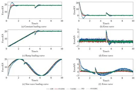
Fig.9 Experimental results
Fig.9(e) and 9(f) shows that INADRC track the sinusoidal signal at 0.3 s,and the average error of INADRC is about 2.35%.In order to further quantitatively evaluate the performance of the four control methods,the mean square errorμand ITAE are introduced for further comparison and explanation.The results are obtained shown in Table 4.It can be seen that under the four tracking signals,the mean square error and ITAE indicators of INADRC are smaller than PID,NADRC,and ONADRC.
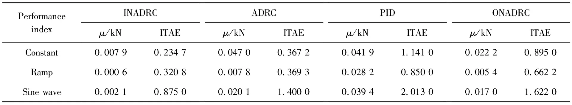
Table 4 Performance index
The error rates are shown in Table 5.The average error rates of INADRC,NADRC,PID,and ONADRC are 2.35%,3.5%,6.5%,and 3.1%.Experimental results show that INADRC is superior to NADRC,PID,and ONADRC in terms of control accuracy and anti-interference ability,which is consistent with the simulation results.
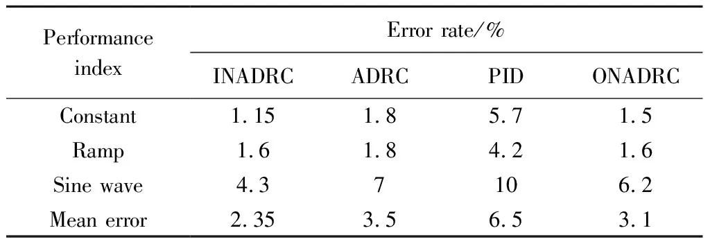
Table 5 Error rate
5 Conclusions
1) Aiming at the problem that the accuracy of electro-hydraulic servo loading systems such as the actuator abrasion experiment platform is not high enough to meet specific needs,an improved nonlinear active disturbance rejection controller is designed,which effectively improves the force tracking control performance.
2) A co-simulation model of AMESim and Simulink for the electro-hydraulic servo loading system is established to improve the efficiency of system design.
3) Compared with PID control,NADRC,and ONADRC,the average accuracy of the INADRC is improved by 4.15%,1.15%,and 0.65% from the simulation and experimental conclusions of three given signals of constant value,sine,and ramp.It can be concluded that INADRC control has higher precision and anti-disturbance ability than other control measures.
4) The GAPSO algorithm is used to obtain a large number of parameters of the nonlinear active disturbance rejection controller,which can meet the system performance index and provide a reference for engineering applications.
 Journal of Measurement Science and Instrumentation2023年4期
- Journal of Measurement Science and Instrumentation的其它文章
- A synchronous scanning measurement method for resistive sensor arrays based on Hilbert-Huang transform
- A covert communication method based on imitating bird calls
- Remote sensing images change detection based on PCA information entropy feature fusion
- An image dehazing method combining adaptive dual transmissions and scene depth variation
- Research on restraint of human arm tremor by ball-type dynamic vibration absorber
- Drive structure and path tracking strategy of omnidirectional AGV