
A real-time laser stripe center extraction method for line-structured light system based on FPGA
2024-01-08 09:11SUZhongyuanKANGJiehuFENGLuyuanLIHongtongZHANGZhenSUNZefengWUBin
SU Zhongyuan,KANG Jiehu,FENG Luyuan,LI Hongtong,ZHANG Zhen,SUN Zefeng,WU Bin
(State Key Laboratory of Precision Measuring Technology and Instruments,Tianjin University,Tianjin 300072,China)
Abstract:Laser stripe extraction serves to be a crucial technique in the line-structured light system,and its accuracy and speed are directly related to the measurement performance.However,the traditional Hessian matrix method may produce redundant centers and missing centers,which will limit its accuracy and robustness.Besides,the complex calculation of the method makes it difficult to be applied in real-time measurement.In order to overcome these issues and achieve real-time center extraction,an improved FPGA-friendly laser stripe center extraction method is proposed.A novel judgment function is designed to replace the maximum eigenvalue,and the numerical difference between the centers and the other domains is more salient.The center judgment criteria are modified and the non-maximum suppression is used to deal with the redundant and missing centers.Furthermore,the proposed method is implemented in FPGA to achieve real-time processing.The calculations are rationally optimized to reduce resource utilization and delay time without reducing the accuracy.The mean absolute errors are 0.003 9 pixel,0.037 3 pixel,0.052 0 pixel,and 0.064 6 pixel,and the root mean square deviations are 0.006 8 pixel,0.046 9 pixel,0.065 4 pixel,and 0.081 1 pixel,respectively,in the accuracy experiment with the noise deviations of 0,0.01,0.02,and 0.03.The running and delay time of the proposed method in FPGA are 14.89 ms and 216.42 μs.The experimental results verify that the proposed method is highly accurate,robust,and time-efficient.
Key words:laser stripe extraction method; Hessian matrix method; redundant and missing centers; field programmable gate array (FPGA); line-structured light system
0 Introduction
Line-structured light is a three-dimensional (3D) measurement technology with the advantages of high precision,low cost and decent flexibility[1-3].It has been widely used in 3D reconstruction,heritage modeling and industrial inspection[4-8].Fig.1 shows the schematic of a line-structured light system.The laser stripe image modulated by the object’s surface is captured by the camera.And the laser stripe center is extracted to calculate the 3D coordinate of the object[9].As a result,the accuracy and speed of the laser stripe center extraction directly affects the performance of the system[10].Several methods have been proposed to extract the laser stripe center,such as the extreme value method[11],gray gradient method[6],curve fitting method[12-13],center of gravity method[14-16],grayscale moment method[2,17],and Hessian matrix method[5,7,18-19].Over the years,efforts are made to improve the accuracy,speed and robustness of these methods,especially for the center of gravity method[3,6,10,20]and the Hessian matrix method (aka Steger method)[1,21-24].The center of gravity method is favored for its high speed and simple implementation,while its accuracy,robustness,and anti-noise capability are relatively limited[18,25].Whereas the Hessian matrix method can achieve better precision and stability,but suffers from the weakness of high computation and low speed[6,9,13,15].
Many researchers have dedicated to improving the speed of the Hessian matrix method to promote its application for real-time measurement scenarios.Cai et al.calculated the normal direction of the laser stripe by using the principal component analysis,making it three times faster than the traditional Hessian matrix method[26].Zhang et al.used a fast threshold method to obtain the initial position,and derived the normal direction through local quadratic curve approximation,which could increase the extraction efficiency by about 3 times[24].Although the two methods could achieve a shorter processing time,the accuracy is negatively affected simultaneously due to the calculation simplification.Liu et al.utilized GPU to accelerate the Hessian matrix method,which was over 110 times faster than the CPU-based method[5].Jiang et al.proposed a field programmable gate array (FPGA) implementation scheme for the Hessian matrix edge detection,within which a box-filter was used to simplify the Gaussian convolution.Although the FPGA implementation could achieve a 232 times speedup over software,its accuracy decreased due to the massive calculation simplification[27].FPGA is more suitable to accelerate the laser stripe center extraction method.Several studies have been explored the implementation of the computationally simple laser stripe center extraction methods in FPGA,including the center of gravity method[16],gray gradient method[28],and template method[29].
However,the performances of these methods are not as accurate and robust as the Hessian matrix method.Pang implemented the Hessian matrix method in FPGA to accelerate the method[30].However,the possible problems using the Hessian matrix method in laser center extraction were not considered.These approaches indicate that FPGA has great potential in accelerating the laser stripe center extraction,and it will compensate for the speed limitation of the method.
Apart from the low speed,the Hessian matrix method possesses another weakness in laser stripe center extraction.Due to the non-ideal grayscale distribution and the discretization errors,there may be redundant centers and missing centers during the extraction[22,31].Redundant centers are removed by using the linking algorithm with a function that includes the distance and the angle between two centers[32],but it is unsuitable for implementation in FPGA.Hu et al.used the canny method to assist the removal of redundant centers[22].A normalization Sigmoid-Gaussian function was employed to determine the real centers[21,31].The functions are quite complex,and the function numerical difference between the real centers and the other pixels is not large enough to distinguish the real centers robustly.Moreover,these methods only focus on the removal of redundant centers,but have not taken the missing centers into consideration.
An improved FPGA-based laser stripe extraction method is proposed and implemented.To deal with the redundant and missing centers,an effective judgment function is proposed,the center judgment criteria are modified,and the non-maximum suppression is used.The proposed method is designed based on the characteristics of FPGA and is suitable to be implemented in FPGA.The computation process is rationally optimized in FPGA implementation,which reduces the resource utilization and latency.The proposed method can realize higher accuracy,robustness,and speed than the traditional Hessian matrix method and can be applied in real-time scenarios.
1 Problems and proposed method
1.1 Hessian matrix method
The Hessian matrix method was first proposed to detect the centers and the edges in remote sensing images and medical images[32].As this method is not specifically designed for laser stripe center extraction,it has certain issues that need to be concerned.In the Hessian matrix method,the standard deviation of the Gaussian kernel is required to match the width of the laser stripe,and the salient centers are selected by the maximum eigenvalue[32].However,since the laser stripes are only a few pixels wide in the line structure light system,the standard deviation of the Gaussian kernel needs to be relatively small,which may lead to a small Gaussian kernel size and generate computational errors.Moreover,the non-ideal grayscale distribution of the image and the discretization error may also lead to computational errors.Therefore,it is difficult to determine a proper threshold of the maximum eigenvalue,especially in practical scenarios.A demonstration of the extraction results from the Hessian matrix method is shown in Fig.2.
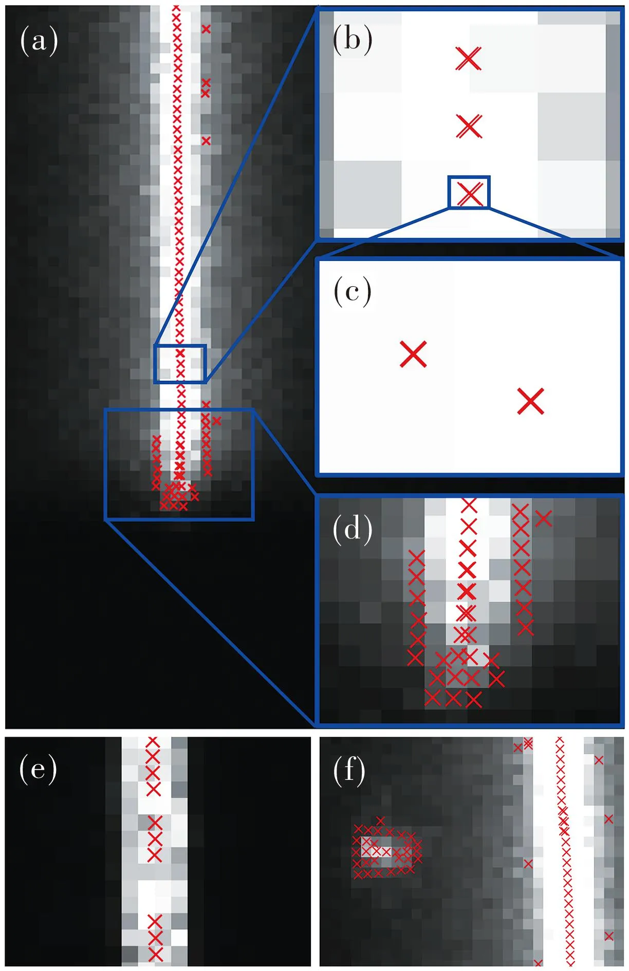
Fig.2 Hessian matrix method’s problems:(a) redundant centers,(b) redundant centers within a short distance,(c) enlarged view of a part in (b),(d) redundant centers at stripe endpoint,(e) missing centers,(f) false centers of reflection points
The images shown in Fig.2 are cropped versions from the laser stripe images in real scenarios.Here,the threshold for the maximum eigenvalue is deliberately relaxed to show the problem more clearly.To find out the reason of the problems caused by the Hessian matrix method,a simulated laser stripe model is established.Thex-axis and they-axis of the simulated image are assumed to be perpendicular and parallel to the laser plane.And the grayscale distribution of the laser stripe obeys the Gaussian distribution in the cross-section perpendicular to the laser plane.The simulated image is designed to have a slightly tilted stripe and a dot,and the grayscale distribution of the simulated model is shown in Fig.3(a) and expressed as
(1)
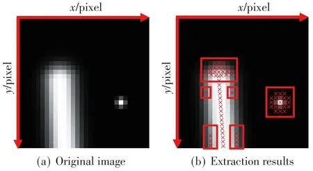
Fig.3 Simulated stripe model
wherex,yare the pixel coordinate of the image;I0,I1are the maximum grayscale of the stripe and the dot,respectively;σa,σbare the standard deviation of the grayscale distribution of the stripe and the dot,respectively;x0,y0are the endpoint of the stripe;x1,y1are the center of the dot.
The center extraction results by Hessian matrix method are exhibited in Fig.3(b),where the problems mentioned in Fig.2(d) and 2(f) appear.To provide a clearer demonstration,the same notation and the conclusion are adopted[32].In the Hessian matrix method,the requirements of the center are that the subpixel valuespx,pyare within 0.5 and the maximum eigenvalue is properly chosen.The subpixel valuespxandpy,the minimum eigenvalueλminand the maximum eigenvalueλmaxof the simulated image are calculated and shown in Fig.4.
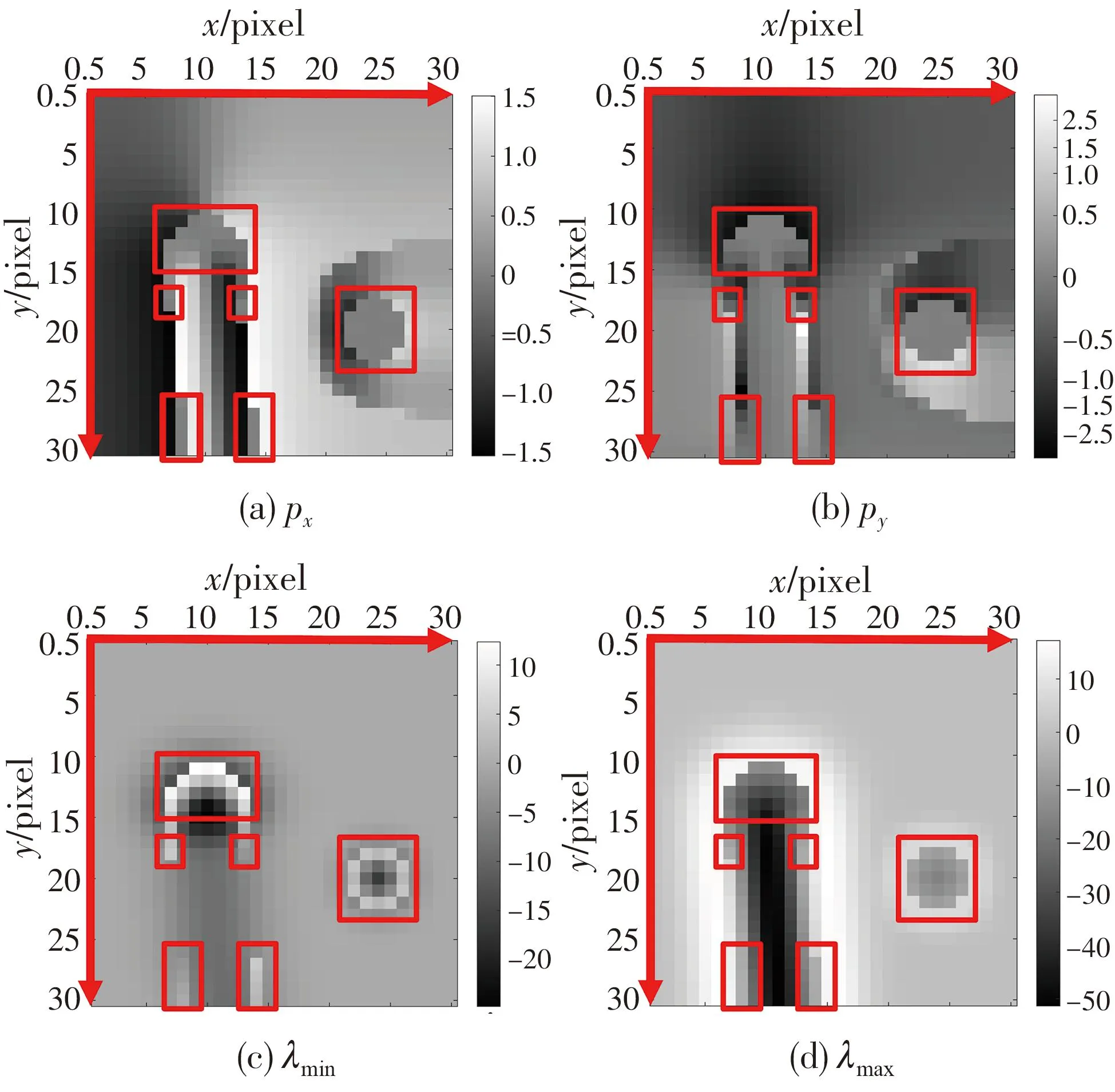
Fig.4 Calculated results of simulated image
In Fig.4,the areas where the redundant centers appear are marked in red boxes.The pixel in red boxes all meet the requirements of the subpixel valuespx,py.Therefore,the redundant center will appear if the threshold of the maximum eigenvalue is set improperly.As shown in Fig.4(d),the maximum eigenvalue at the end of the stripe is similar to the real centers,making it difficult to distinguish the redundant centers.Although the maximum eigenvalues in the other red-marked areas appear to be different from the real centers,it is still considered to be not sufficient.In real scenarios,the maximum eigenvalues in these areas may still be similar to that of real centers due to the non-ideal grayscale distribution and computational errors.It shows that the subpixel valuespx,pyare easy to meet the requirements.And the maximum eigenvalue is not salient enough as a standard to select the real centers.Therefore,if the threshold is set improperly,the redundant points in red-marked areas may arise.
To analyze problems in Fig.2(b) and 2(e),the subpixel valuespx,pyof the redundant and missing centers in Fig.2 is captured,and the values are shown in Tables 1 and 2,respectively.Due to the non-ideal grayscale distribution and computational errors,the absolute values ofpxon both pixels are less than 0.5 in Table 1,and the absolute values ofpxon both pixels are greater than 0.5 in Table 2,resulting in the appearance of redundant and missing centers,respectively.And the redundant centers cannot be removed by the maximum eigenvalue properly.
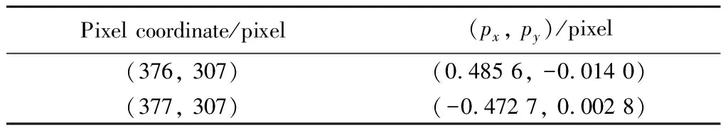
Table 1 Subpixel value of redundant center
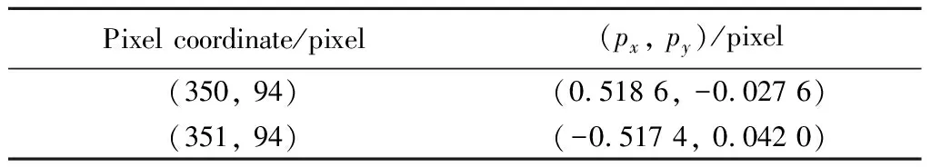
Table 2 Subpixel value of missing center
1.2 Laser stripe center extraction method
In the line-structured light system,only one center is expected to be extracted in the normal direction of the laser stripe for each pixel,whereas the redundant and missing centers are considered to be undesirable.Linking or interpolation techniques have been used to deal with the issues of redundant and missing centers[21].However,these methods are time-consuming,resource-intensive and unsuitable to be implemented in FPGA.The proposed method aims to deal with the redundant and missing centers by the numerical difference among each pixel,and further achieve the implementation in FPGA.Therefore,a new judgment function is proposed,the judgment criteria are modified,and the non-maximum suppression is used.
In order to reduce the computation,only the intermediate values in the extraction process are utilized to constitute the judgment function.As shown in Fig.4(c),the minimum eigenvalue is non-zero where the redundant centers tend to appear.And the image grayscale values in these areas tend to be smaller than the real centers.Therefore,the image grayscale values and the minimum eigenvalue are introduced into the function to increase the numerical difference between the real centers and other points.So the judgment function is
(2)
whereλminis the minimum eigenvalue;λmaxis the maximum eigenvalue;Iis the image grayscale value;k1andk2are the coefficients ofλminandλmax.
The maximum and minimum eigenvalues of the Hessian matrix of a pixel are the maximum and minimum values of the second-order directional derivatives of the pixel.In Fig.4(c) and 4(d),the maximum eigenvalue is at the stripe centers and stripe endpoint,and the dot is a large negative value,while the minimum eigenvalue is at the stripe endpoint and the dot is a large absolute value.As a result,if thek1andk2are negative,the judgment function will be relatively large at the stripe centers,and relatively small at the stripe endpoint and the dot.The values ofk1andk2may vary slightly in different sensor,and can be determined by comparative experiments.Here,thek1andk2are both set to be-5.The distribution of the judgment function value for the simulated image is shown in Fig.5.Compared to the maximum eigenvalues,the numerical difference of the proposed judgment function between the real centers and other domains is more distinct.It makes the judgment function more robust and easier to set a fixed threshold.

Fig.5 Value of judgment function for simulated image
To overcome the issue of missing center,the subpixel threshold is set to be greater than 0.5.However,it may also lead to an increase of redundant centers.Here,non-maximum suppression is used to remove the redundant centers.In the proposed method,the initial centers are detected as long as the subpixel value and the judgment function can meet the fixed threshold requirements.Then the judgment function value of other pixels is set to zero.Subsequently,the judgment function value of the initial centers is compared with the two adjacent pixels in the normal direction,as shown in Eq.(3) and Fig.6.
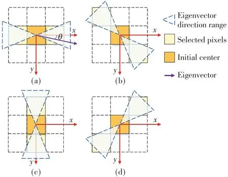
Fig.6 Adjacent pixels selected by normal direction:(a)[-22.5°,22.5°]∪[157.5°,202.5°],(b)[22.5°,67.5°]∪[202.5°,247.5°],(c)[67.5°,112.5°]∪[247.5°,292.5°],(d)[112.5°,157.5°]∪[292.5°,337.5°]
In Eq.(3),the comparison result indicates whether the initial center is a real center.If the judgment function value of the initial center is greater than the value of two adjacent pixels,it will be regarded as a real center.
(3)
whereV2is the comparison result; (x0,y0) is the pixel coordinate of the initial center;fis the judgment function;θis the angle between normal direction andx-axis.
The proposed laser stripe center extraction method is described as follows.
1) Apply Gaussian filter to the image to remove the laser scatter noise.
2) Convolve the image with the derivatives of the Gaussian kernel to calculate the first and the second partial derivatives of the images.
3) Calculate the eigenvalues and the eigenvector of the Hessian matrix,the subpixel value and the judgment function value.
4) Extract the initial centers with the threshold requirements of the subpixel value and the judgment function value.
5) Compare the judgment function value of adjacent pixels to determine the real centers.
2 FPGA implementation
In order to make the proposed method run in real-time and realize the immediate processing of the output image data from the CMOS image sensor,it has been further implemented in FPGA.Fig.7 shows the block diagram of the FPGA implementation.
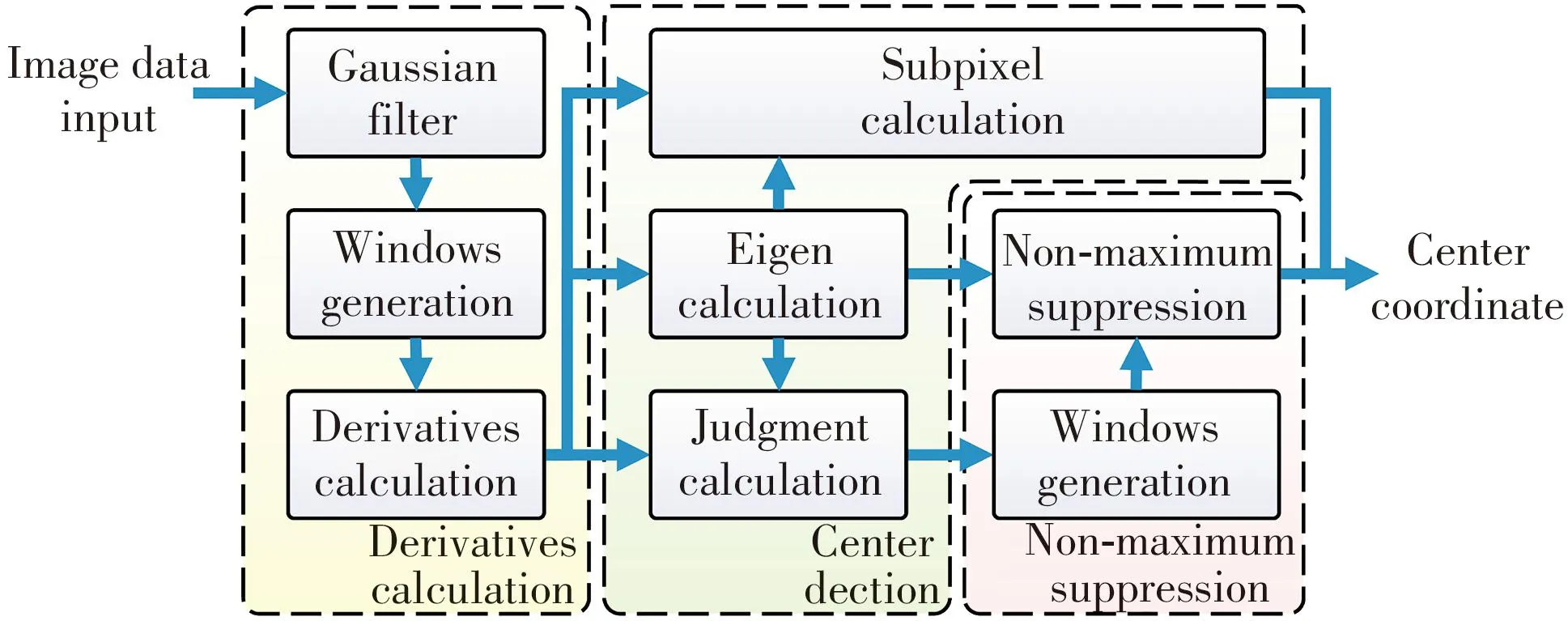
Fig.7 Block diagram of FPGA implementation
The image data from the image sensor is serially sent into the derivatives calculation module,where the first and the second partial derivatives of the image are calculated.Subsequently,in the center detection module,the subpixel coordinate of the laser stripe centers,eigenvalue,eigenvector and the judgment function value are calculated.The non-maximum suppression module determines the real centers based on the proposed method.The laser stripe center extraction result is constituted of the subpixel coordinate and the non-maximum suppression result.
2.1 Derivative calculation module
To obtain the first and the second partial derivatives,the image is convolved with the derivatives of the Gaussian kernel[32].The pixel-streaming image data input is provided by the CMOS image sensor.And as shown in Fig.8,the pixel stream is first sent into the Gaussian filter module.Then the filtered pixel is serially sent into the window generation module.The window generation module hasnline buffers,with each line buffer caching one row pixel data.Two state machines are used to pad the images,but are omitted in the figure.For each clock,one pixel data is read out from each line buffer,forming an×1 pixel×pixel data matrix[Pn…P2P1]T.
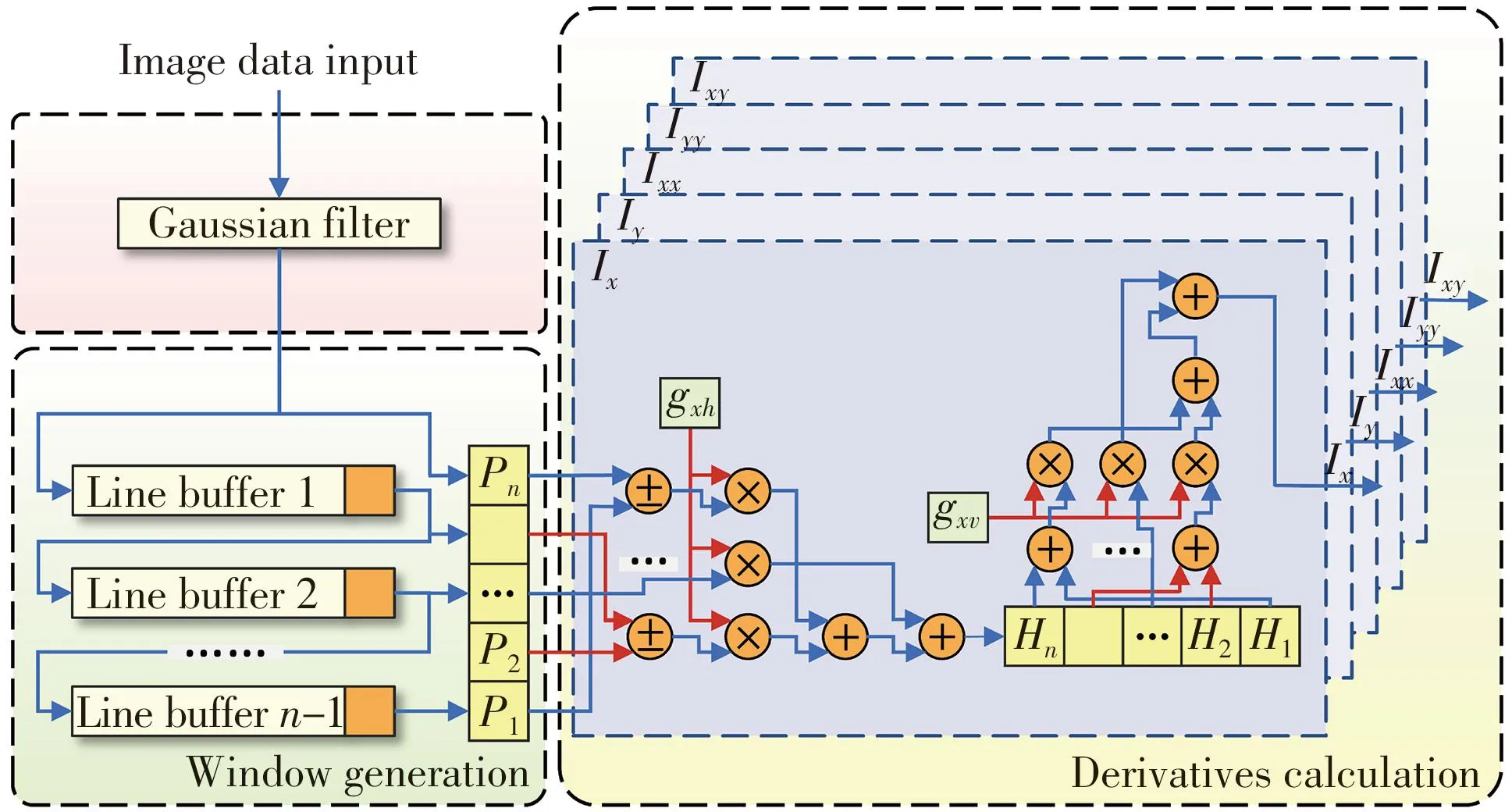
Fig.8 Schematic of derivatives calculation module
Subsequently,then×1 pixels data matrix is used to calculate the derivatives of the image.It is worth mentioning that the first and the second derivatives of the Gaussian kernel are all separable and symmetric,which can be utilized to simplify the process.The separability of the Gaussian kernel allows the two-dimensional convolution to be separated into two one-dimensional convolutions.Moreover,the symmetry of the Gaussian kernel further reduces the requirement of multiplications during the one-dimensional convolution.As shown in Fig.8,the image is first convolved in the column direction,and then the intermediate result[Hn…H2H1]is convolved in the row direction.In one-dimensional convolution,the pixel data is first added or subtracted to the pixel data at the symmetrical position,and then the results are multiplied by the corresponding Gaussian kernel coefficientsgxhandgxv.After summing all the results,the result of the one-dimensional convolution is obtained.Compared with the two-dimensional convolution process,the number of additions and multiplications is reduced fromn2-1 andn2to 2(n-1) andn+1,respectively.The calculation of the other partial derivativesIy,Ixx,Iyy,Ixyhave the same schematic asIx.After processed by the derivative calculation module,the first and second partial derivativesIx,Iy,Ixx,Iyy,Ixyof each pixel are obtained.
2.2 Center detection module
In the center detection module,the eigenvalues,eigenvector,subpixel coordinates and judgment function value are calculated,and the original center is detected.Fig.9 is the schematic of the center detection module.In general,the eigenvalues of the Hessian matrix are calculated by
(4)
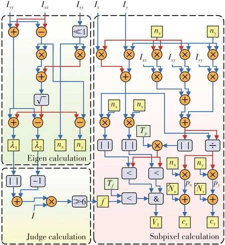
Fig.9 Schematic of center detection module
(5)
Subsequently,the maximum and minimum eigenvalues and the eigenvector are obtained by
λmax=max(|λ1|,|λ2|),
(6)
λmin=min(|λ1|,|λ2|),
(7)
(8)
However,in the laser stripe center extraction,the maximum eigenvalue of the pixels near the laser stripe center must be a large negative value.Comparing Eqs.(4) and (5),λ2must be smaller thanλ1,and thus the maximum eigenvalue near the laser stripe must be equal toλ2.Since the eigenvalues in other positions will not affect the extraction results,the calculation is simplified by directly usingλ2as the maximum eigenvalue.The experiment results show that the simplified extraction results are not affected.In general,the eigenvector needs to be normalized.But in the proposed method,the eigenvector is only used to calculate the subpixel value,as given by
(px,py)=(tnx,tny),
(9)
where
(10)
As shown in Eqs.(9) and (10),the numerator and denominator of the subpixel values both include the quadratic terms of the eigenvector.Therefore,in the proposed method,the eigenvector does not need to be normalized and can be further simplified to Eq.(11),which removes the division and is more suitable to be implemented in FPGA.
n=[nx,ny]=
(11)
During the extraction,the eigenvalues are only used to calculate the judgment function value,and the coefficients 1/2 in Eqs.(4) and (5) can be omitted.In the proposed method,the calculation of subpixel values requires division which takes several clocks in FPGA.As for the comparison of the subpixel values,herein,its numerator is directly compared to the multiplication of the denominator and the threshold during the division process rather than after,which will reduce the delay time of the implementation in FPGA.
As shown in Fig.9,the second partial derivativesIxx,Iyy,Ixyare used to calculate the eigenvaluesλ1,λ2and the eigenvector[nx,ny]of the Hessian matrix.The first partial derivativesIx,Iy,the second partial derivativesIxx,Iyy,Ixy,and the eigenvector[nx,ny]are used to calculate the subpixel values[px,py]according to Eqs.(9) and (10).The coordinates of the center[cx,cy]are obtained by summing the subpixel values[px,py]and the values of the row and column counters[Nx,Ny].Meanwhile,the judgment function valuefis obtained by the eigenvaluesλ1andλ2.The valuefis compared with the thresholdTf,and the numerator of the subpixel values are compared to the multiplication of its denominator and the thresholdTp,which jointly constitutes the initial center detection resultV1.
2.3 Non-maximum suppression module
The non-maximum suppression module is designed to remove the redundant centers from the initial center detection result.The eigenvector is used to determine the normal direction of the laser stripe as shown in Fig.6.To simplify the calculation,the normal direction range is determined by comparing the magnitude of two eigenvector components,rather than using the inverse trigonometric function to calculate the angle.The relation between the magnitude of the eigenvector components and the normal direction is shown in Table 3.
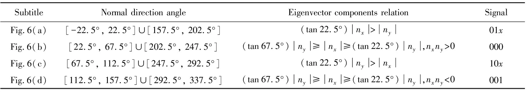
Table 3 Relation between eigenvector and normal direction
As shown in Fig.10,in order to determine the normal direction of the laser stripe,two comparators and an exclusive-or gate (XOR gate) are used.Tθis equal to the tan 22.5°.The two comparators serve to compare the (tan 22.5°)|nx|>|ny|and (tan 22.5°)|ny|>|nx|,while the inputs of the XOR gate are the sign bit of the eigenvector components.The results are combined to determine the normal direction corresponding to Table 3.
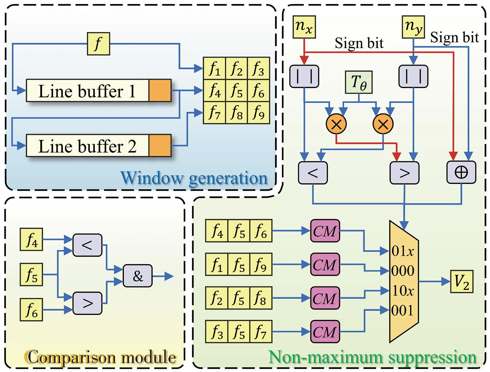
Fig.10 Schematic of center calculation module
In Fig.10,the window generation module generates the 3×3 judgment function value matrix.CM is the comparison module.And the middle valuef5is compared with the values of the adjacent pixels in four directions,respectively.The four comparison results are selected by the comparison results of the eigenvector,forming the real center enable signalV2.
3 Experiment
To verify the accuracy and robustness of the proposed method,a line-structured light system is designed.The system consists of a custom-made line structured laser source (405 nm,20 mW),a CMOS image sensor (ON semiconductor MT9V034),a lens (12 mm,AZURE Photonics 1228MAC),a ZYNQ board (Xilinx Zynq-7020) and a 1D motorized stage (Thorlabs DDS220/M).The camera,line laser plane and moving axis of the system are calibrated[5,18,33].
The extraction results of the traditional Hessian matrix method and the proposed method are shown in Fig.11.Compared with the results of the traditional method,the proposed method can remove the redundant centers and re-find the missing centers.Therefore,the proposed method can provide more complete and uniform 3D point clouds.Fig.11(a) and 11(b) are cropped from the same images,and it can be noticed that the redundant centers appear at the end of the laser stripe in Fig.11(a),while a missing center also appears because the threshold of the maximum eigenvalue is too high.The proper fixed threshold without producing redundant and missing centers simultaneously cannot be obtained by the traditional Hessian matrix method.
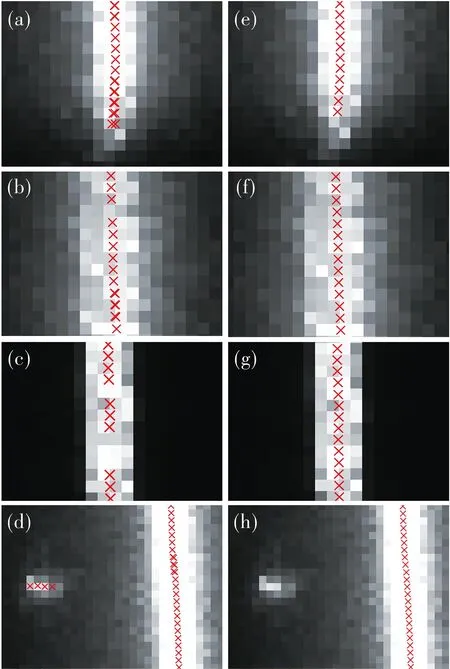
Fig.11 Laser stripe center extraction results:(a)-(d) traditional method,(e)-(h) proposed method
Besides,the judgment function proposed in this method is simple but highly robust,and setting a fixed threshold of the judgment function is not strict as the traditional Hessian matrix method.10 images in different scenarios are used to test the threshold range for not producing redundant centers and missing centers.The proposed method,the traditional Hessian matrix method and the method described in the literature[31]are compared and tested in the experiment.The results show that the threshold range of the proposed method is 39.9 to 71.2.However,since the tested images vary in stripe brightness,stripe width and background brightness,the traditional Hessian matrix method and the method reported by the literature[31]fail to find a fixed global threshold for all the images.The judgment function in the proposed method is more robust and easier to set a fixed threshold,which will simplify the calculation and reduce the resource utilization of FPGA.
The requirements for the subpixel values in the proposed method are relaxed to re-find the missing centers.However,attributed to the proper design of the judgment function,the accuracy and robustness of the proposed method have not been affected,which has been verified by the simulated laser stripe images similar to Fig.3(a).In the simulated image,the standard deviation of the Gaussian grayscale distribution is 2.2.The artificial speckle noise with the deviation of 0.01,0.02 and 0.03 is randomly added to the simulated image,and 100 simulated images are tested for each deviation.Tables 4 and 5 present the mean absolute error (MAE) and the root mean square deviation (RMSD) of the results extracted by the proposed method,the traditional Hessian matrix method and other methods[10,31].
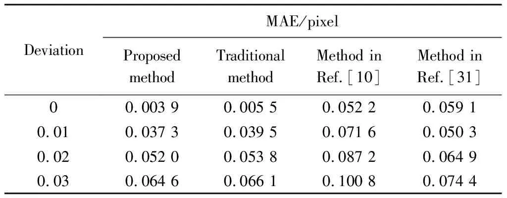
Table 4 Mean absolute error of four methods
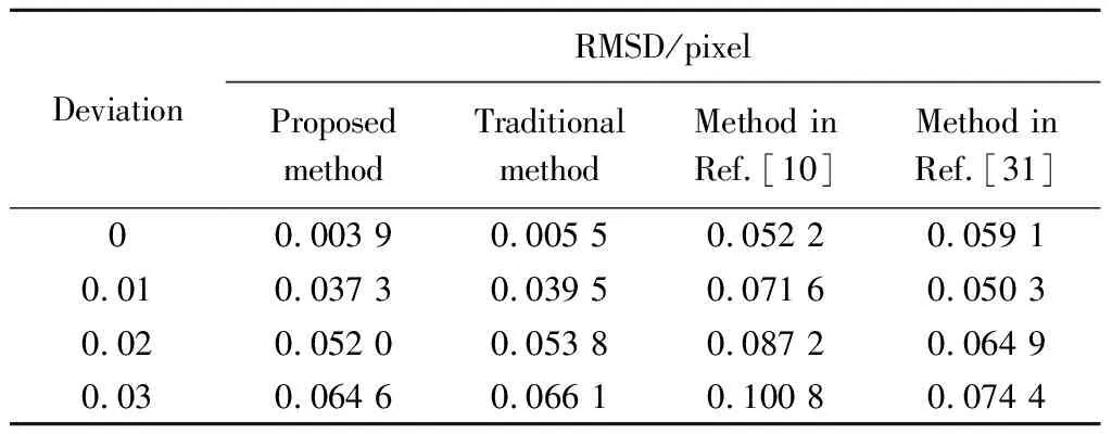
Table 5 RMSD of four methods
The proposed method maintains the highest accuracy among the four methods.During the experiment,the other three methods would generate redundant centers at the end of the stripes,whereas there is a missing center in the results of the traditional Hessian matrix method,as shown in Fig.12.In fact,the accuracy and robustness of the proposed method are on the same level as the traditional Hessian method in the continuous stripe domain.However,at the end of the stripe,the redundant centers are extracted by the traditional method,and thus the error of the results is increased.
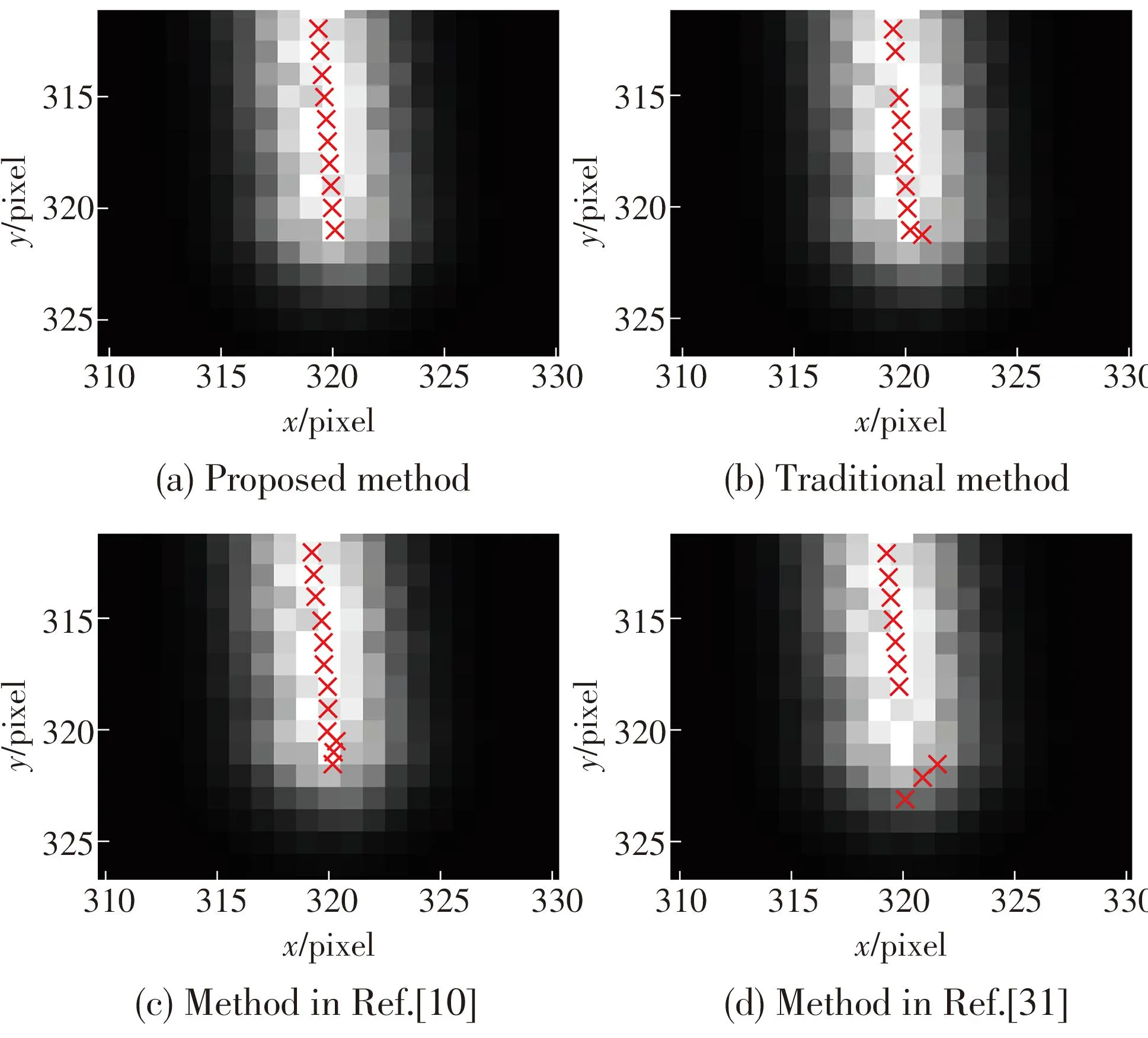
Fig.12 Extraction results of a simulated image with deviation of 0.01
Subsequently,the performance of the proposed method is evaluated by measuring a marble standard step.A 10 mm step and a 20 mm step with 0.000 5 mm manufacturing error are measured 6 times for accuracy and repeatability evaluations.For each measurement,100 laser stripe images are captured to obtain a 3D point cloud,from which the distance between the two surfaces of the standard step is measured.The measurement results of the standard step are shown in Table 6.The mean absolute errors (MAE) are 0.005 4 mm and 0.006 0 mm,and the standard deviations (STD) are 0.000 34 mm and 0.000 44 mm,respectively,indicating an accurate and stable measurement performance.
Furthermore,the proposed method has been implemented in the FPGA component of the ZYNQ board (Xilinx Zynq-7020) to realize real-time extraction.Table 7 presents the resource utilization of the FPGA implementation.As the image sensor serially sends the image data into the FPGA pixel by pixel,the laser stripe center can be extracted in real-time.The FPGA runs at the pixel clock of the image sensor.For an image of 640×480 pixel×pixel,357 419 clock cycles are needed for the center extraction.And the running time of the proposed method in FPGA is 14.89 ms at 24 MHz pixel clock.
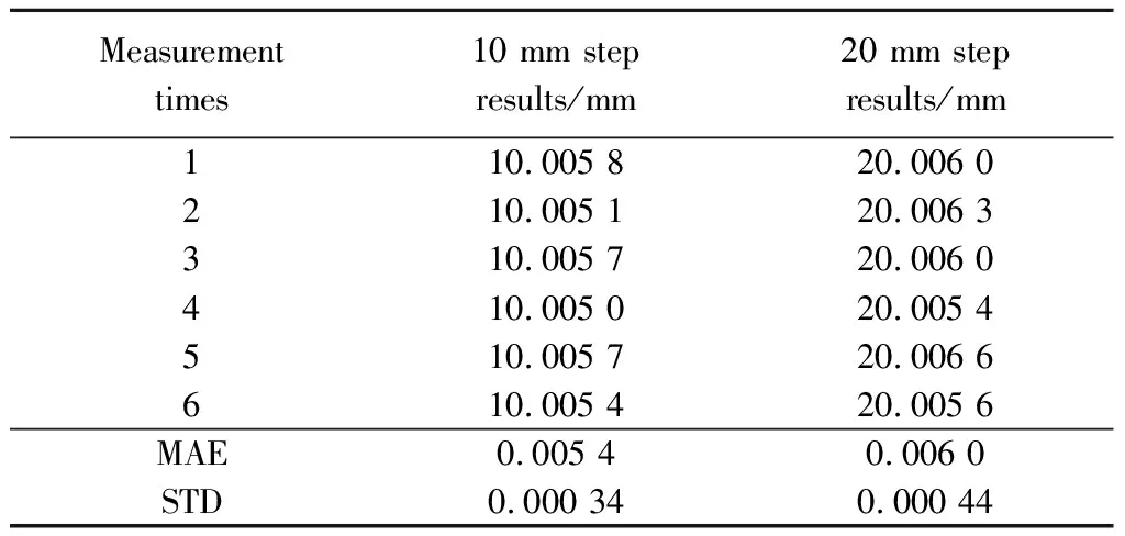
Table 6 Measurement results of standard steps

Table 7 Resource utilization of FPGA implementation
In order to verify the time-efficiency of the proposed method in FPGA,the traditional Hessian matrix method,the methods in references[10,31]and the proposed method are implemented in software by using a computer with an Intel i5-6300HQ CPU.1 000 laser stripe images are used to obtain the average running time of the four methods in CPU.The resolution of the tested images is 640×480 pixel×pixel.Table 8 shows the speed comparison results.Combining Tables 4 and 5,it indicated that the proposed method implemented in FPGA has the highest accuracy and speed.
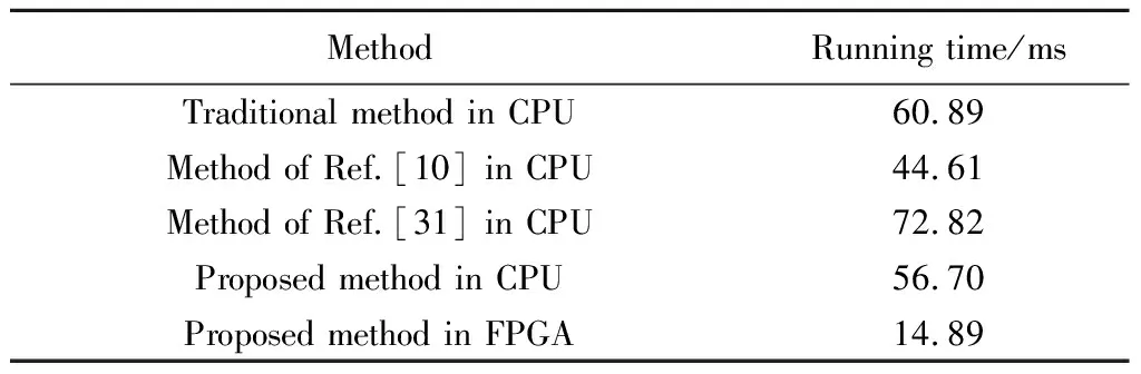
Table 8 Average running time for an image of four methods
What’s more,the delay time of the proposed method in FPGA is extreme low.Since the image sensor is directly connected to the FPGA,the extraction can be performed once the first pixel data of an image is input.It takes only 216.42 μs to complete the extraction after an image is fully input.And the performance of the proposed method in FPGA has great potential but is limited by the 24 MHz pixel clock now.The implementation software shows that the maximum clock of the FPGA implementation is 125 MHz.If the pixel clock is up to 125 MHz,the running time of the proposed method will be 2.89 ms and the delay time will be 41.55 μs.
4 Conclusions
A real-time laser stripe extraction method for the line-structured light system is proposed and further implemented in FPGA.A simple and effective judgment function is designed,the center judgment criteria are modified,and the non-maximum suppression is used to overcome the issues of the traditional Hessian matrix method.The calculation of the proposed method is rationally optimized without any reduction in accuracy,making it more suitable to be implemented in FPGA.The experiments confirmed that the proposed method is more accurate,robust and time-efficient compared to the other methods.In the accuracy experiment with the noise deviations of 0,0.01,0.02 and 0.03,the mean absolute errors are 0.003 9 pixel,0.037 3 pixel,0.052 0 pixel and 0.064 6 pixel,and the root mean square deviations are 0.006 8 pixel,0.046 9 pixel,0.065 4 pixel and 0.081 1 pixel,respectively.The running and delay time of the proposed method in FPGA are 14.89 ms and 216.42 μs,which realizes real-time processing of the output image data from the CMOS image sensor.And the speed of the method still has great potential to be further improved by increasing the clock frequency.Based on the works in this paper,more innovative ideas can be promoted for further applications of the Hessian matrix method in the line-structured light system.
 Journal of Measurement Science and Instrumentation2023年4期
- Journal of Measurement Science and Instrumentation的其它文章
- A synchronous scanning measurement method for resistive sensor arrays based on Hilbert-Huang transform
- A covert communication method based on imitating bird calls
- Remote sensing images change detection based on PCA information entropy feature fusion
- An image dehazing method combining adaptive dual transmissions and scene depth variation
- Research on restraint of human arm tremor by ball-type dynamic vibration absorber
- Drive structure and path tracking strategy of omnidirectional AGV