聚苯胺-还原氧化石墨烯复合材料的比电容及超级电容性能
2017-11-01 18:11曾向东赵晓昱韦会鸽王彦飞沙作良
物理化学学报 2017年10期
曾向东 赵晓昱 韦会鸽 王彦飞 唐 娜 沙作良
(天津科技大学化工与材料学院,天津 300457)
聚苯胺-还原氧化石墨烯复合材料的比电容及超级电容性能
曾向东 赵晓昱*韦会鸽 王彦飞 唐 娜 沙作良
(天津科技大学化工与材料学院,天津 300457)
通过同步还原聚苯胺(PANI)-氧化石墨烯(GO)复合物制备得到了聚苯胺-还原氧化石墨烯(PANI-rGO)。由于复合材料中PANI提供了氧化还原反应的电荷,使得PANI-rGO复合材料具有较大的比电容。通过扫描电子显微镜(SEM),紫外-可见光谱和热重量分析法(TGA)对复合物进行了结构和形态的分析。复合材料的形态呈薄片状,聚苯胺是均匀地包裹在氧化石墨烯上的。当电流密度为20 A∙g−1时,PANI-rGO复合材料的比电容可高达1069 F∙g−1(1.71 F∙cm−2),是PANI-GO复合材料的五倍,这是因为复合材料中还原氧化化石墨烯的大比表面和高电导性所引起的。
聚苯胺-还原氧化石墨烯;聚苯胺-氧化石墨烯;比电容;操作电压
1 Introduction
Graphene (GN), one kind of two-dimensional sp2-hybridized carbon material which has semimetal high crystal structure1,2,high specific area and good conductivity, shows potential in supercapacitor materials. GN based materials attracted many researchers developing supercapacitors3−7, aimed at increase power and energy density as well as lowering fabrication costs while using environmentally friendly materials.
Based on the reports by researchers, using GN has specific surface area of 2000 m2∙g−1, the electric double-layercapacitance (EDLC) was about 20 μF∙cm−28. Introducing pseudocapacitance, accumulates charges at the electrode/electrolyte interface, accompanying with the surface redox reaction at high surface area electrode, can increase the energy density to 10 times larger than EDLC9. PANI contained pseudocapacitive materials of the redox species, extend the application in supercapacitors10,11.
It was reported that transition metal oxides and conducting polymers have been used as electrodes in pseuodocapacitors12,13. Polyaniline-reduced graphene oxide(PANI-rGO) has been considered as one of the rGO based materials for supercapacitors14−17, which is one of the common conductive polymers known as reproducible control of the macromolecule via a simple synthesis method. Moreover, the ability of protonation-deprotonation of PANI make the protons having a significant role in the charge compensation process,which is suitable to use as an energy storing material18.
The PANI-rGO composite material has recently been used for electric double-layered capacitors of high capacitance. Such hybrid of PANI and rGO, enhanced electrical conductivity,electroactivity and electrochemical stability19−22, prospectively could be used as supercapacitors.
The composite of PANI-rGO can be obtained by simultaneous reducing PANI-graphene oxide (GO) particles,which was synthesized via in situ oxidation polymerization in the presence of GO23,24. However, PANI-GO was also considered as exhibiting high capacitance25−27. It is difficult to be understood that the insulating GO in PANI-GO can show high capacitance. On the other hand, to prepare PANI-rGO, different researchers use different molar ratio of aniline to ammonium peroxydisulfate (APS) e.g. 4 : 120, 3 : 128, 3 : 229,30. This means that PANI was in different oxidation state and was not the emeraldine oxidation state of PANI which has the highest level of conductivity31. When synthesizing PANI, in order to obtain the high conductive PANI, the researchers usually control the molar ratio of anline to APS at 4 : 5 in early years32−37.
So, we prepared PANI-rGO, using the method mentioned above, with the molar ratio of anline to APS at 4 : 5. The capacitance of PANI-rGO reduced by hydrazine was estimated by electrochemical technique. The capacitance of PANI-rGO is compared with that of PANI-GO.
2 Experimental mehthods
2.1 Synthesis of the composites
Graphene oxide, PANI and PANI-GO were obtained basically according to the reported processes38. The oxidant,ammonium peroxydisulfate (APS) (Wako, Japan), with molar ratio of aniline hydrochloride to APS of 1 : 1.25 was added to the mixture slowly. The composite of PANI-GO was washed repetitively with distilled water and centrifuged. The sediment was dried under vacuum at 40 °C. 0.1 mL hydrazine monohydrate was added to 50 mL PANI-GO suspension with concentration of 2 g∙L−1. The as reduced mixture was put in oil bath at 95 °C for 1 h20,39,40. The product was oxidized by adding 0.0600 g APS20, followed by centrifuged -wash process repetitively with 1 mol∙L−1HCl. The dispersion-centrifugation process was iterated until the supernatant showed no absorbance band of PANI. The iteration was normally three or four times. In order to know the amount of PANI-rGO particles with rectangular size of 1.0−1.5 μm38in the acid solution, 5 mg of PANI-rGO suspension was filtered by the PTFE filter paper (JGWP04700, Omnipore Membrane Filter: φ 47 mm,pore size: 0.2 μm) and washed by ion-exchanged distilled water.The mass of the PANI-rGO in the suspension can be obtained after drying under vacuum at 60 °C for 8 h.
2.2 Characterization
SEM photographs were taken with JSM-6701F (JEOL,Tokyo, Japan). UV-Vis absorption spectra were measured by V-670 spectrophotometer (Jasco, Japan). Thermogravimetric analyses (TGA) was carried out with Thermo Plus, TG8120(Rigaku, Tokyo, Japan).
2.3 Fabrication of electrode
The working electrode was prepared by casting the PANI-rGO or PANI-GO suspension onto a platinum electrode with a diameter of 1.6 mm. Typically, 3.55 mg of PANI-rGO composite was dispersed in 1.000 g of 1 mol∙L−1HCl solution,forming the PANI-rGO suspension. And 15.50 mg of the suspension was then dropped onto the platinum electrode and dried in an oven before the electrochemical test.
2.4 Electrochemical measurements
A three-electrode cell system was used to evaluate the electrochemical performance in 1 mol∙L−1HCl solution. The reference electrode was Ag/AgCl in saturated KCl. The counter electrode was a platinum coil wire. Cyclic voltammetry (CV)and galvanostatic charge-discharge process were carried out with an electrochemical workstation (Ivium compact stat.Netherlands). The electrochemical impedance spectroscopy(EIS) carried out with the above workstation, equipped with a lock-in amplifier. Applied alternating voltage was 10 mV in amplitude. The applied frequency was from 10 kHz to 0.1 Hz.
3 Results and discussion
3.1 Characterization of composites
GO dispersed in water shows color of yellow-brown. When GO was chemically reduced, its color would change to black,standing for that the rGO is obtained. Fig.1 shows the UV-Vis spectra of GO, rGO, PANI, PANI-GO and PANI-rGO. The UV-spectrum of GO shows the absorption band at 231 nm and a second absorption peak around 300 nm,which is agreed with other research reports41. After reduced by hydrazine, the C/O atomic ratio become larger than that in GO. Agglomerative black material was obtained which indicating that the conjugated carbon atoms are restored and the oxygenfunctionalities are removed42. As shown in Fig.1, there is only one shifted adsorption band of rGO around 260nm. In addition,GO shows suddenly weight loss around 170−200 °C from the result of TGA (in Fig.2), ascribe to the decomposition of oxygen function groups on GO into H2O, CO and CO243. And there is no weight loss in the domain 170−200 °C for rGO,suggesting that the thermally labile oxygen-functionalities in GO was removed by hydrazine treatment. There is fast weight loss of graphite in the range of 600−700 °C, which is almost the same as the behavior of reduced GO. The weight loss of GO around 600−700 °C caused by the oxidation of graphene in GO with air. In the large temperature range of 200−600 °C, the weight loss may be related to not decomposition completely of oxygen-containing groups in the range of 170−200 °C and some of the GN in GO oxidized by air44.
As seen in Fig.1, there are two absorption peaks for PANI in 1 mol∙L−1HCl acid solution. The peak around 430 nm is the characteristic of oxidized polyaniline, corresponds to significant protonated polymer molecular chain. Absorption peak of 780 nm is caused by polaronic and bipolaronic band structures31,45. These peaks suggest that PANI is in the emeraldine oxidation state of PANI.
PANI-GO curve in Fig.1 shows absorption bands containing the GO absorption spectrum near 270 nm and that of PANI around 420 nm and 780 nm. The TGA results in Fig.2 show weight loss of GO in the composite of PANI-GO, which is different from the weight loss behavior of pure PANI,indicating that the composite of PANI-GO is formed. However,PANI-GO shows clearer absorption spectrum at 780 nm and more green color than pure PANI and PANI-rGO in the suspension, caused by the increasing of the two polaron bands at such wavelengths39.

Fig.1 UV-Vis spectra of (a) PANI-rGO, (b) PANI-GO, (c) PANI,(d) GO and (e) rGO obtained in 1 mol∙L−1 aqueous acid dispersions.
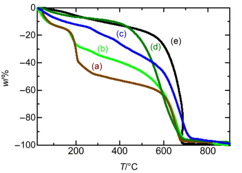
Fig.2 TGA curves of (a) GO, (b) PANI-GO, (c) PANI-rGO,(d) PANI and (e) rGO.

Fig.3 SEM images of (A) PANI-rGO, (B) PANI-GO and (C) PANI; (D) AFM image of the cross section of PANI-rGO film.
The thick films will be formed after a few drops of the suspensions dried on a carbon tape. As shown in Fig.3, SEM results of PANI-GO and PANI-rGO films show shape of flaky morphology. This is the evidence of successfully uniformly coating PANI on rGO, when comparing with that pure PANI(Fig.3(C)) presented the granular morphology. This is mainly corresponding to the polymerization of PANI46−48. The result is in agreement with other research that the polymerization process has no effect on the shape of GO and PANI can uniformly cover the rGO surface49. The cross section of the film by AFM is obtained, showing layered structure (Fig.3(D)).
3.2 Electrochemical Characterizations
The supercapacitance of the composites is expressed by specific capacitance, CSwhich could be calculated from charge capability tested by CV and galvanostatic charge-discharge technique50. For cyclic voltammograms, the specific capacitance was calculated by:

where I is the instantaneous current, v is the scan rate, m is the mass of the active materials on the working electrode with unit of μg. E1, E2are the switching potential range. For galvanostatic charge-discharge curve, the average specific capacitance can be simply calculated by:

where i is charge-discharge constant current, ∆t is the time for the overall potential decrease (ΔE) during discharge. In addition, the energy density ESand power density PSof the electrodes were determined by equation. (3) and (4):


Fig.4 Cyclic voltammograms of (a) PANI, (b) rGO,(c) PANI-rGO and (d) PANI-GO casted on electrode as workingelectrode for v = 10 mV∙s−1.The current values were specific current per unit of mass.
The CV results of PANI-rGO and PANI-GO pasted on electrode are shown in Fig.4 with the potential range from −0.1 to 0.6 V (vs Ag/AgCl) at scan rate of 10 mV∙s−1. It shows a pair of redox peaks for both the PANI-rGO and PANI-GO, relating to the redox transforming of PANI between the leucoemeraldine salt and conductive emeraldine salt, which faradic current involving redox reaction offers high energy density. From the CV results, the capacitance of PANI-rGO and PANI-GO are calculated as 1200 F∙g−1(1.91 F∙cm−2) and 208 F∙g−1(0.33 F∙cm−2), respectively. The small capacitance of PANI-GO possibly attributes by the intrinsic surface nature of GO playing a blocking effect and inhibit the charge transformation51,52. PANI-rGO also shows larger capacitance than that of the simple summation of pure PANI and rGO at the potential range from 0.4 to 0.6 V (vs Ag/AgCl). That can be explained as PANI decreased the agglomeration of rGO, so that the surface area of rGO in the composite is enhanced.
PANI is considered as supercapacitor material mainly because of its faradaic pseudocapacitance. There are two oxidation processes: the initial oxidation and the second oxidation. In the initial oxidation process, as seen in Fig.4,partial protonated amines of PANI in the reduced form are expulsed protons following anions insertion to compensation the charge, resulting in a little solvent transport and forming charged sites of protonated imines. Thereby, large power densities could be obtained, caused by the faster protons expulsion rather than the diffusion of the anions18.
As the energy density is proportional to the square of the voltage, large operating voltage is wanted. When high potential is applied, the second oxidation of PANI can happen, which makes the theoretical specific capacitance of PANI up to 2000 F∙g−150. However, when applied potential larger than 0.6 V, the imine will be hydrolyzed to form benzoquinone18,53. As seen in Fig.5, after the scanning of PANI-rGO going around in circular manner for 20 times from −0.1 to 1 V, PANI is hydrolyzed,even the incorporation of rGO in PANI is regarded as enhancing electrochemical stability of PANI19−22.

Fig.5 Cyclic voltammograms of PANI-rGO casted on electrode as working electrode for 20 scans at v = 10 mV∙s−1.
The CV curve of GO modified electrode in Fig.6, shows almost the same behavior as the bare electrode in 1 mol∙L−1acid solution. Redox of protons in low potential which caused by the hydrogen ions interacting with GO or rGO, indicates that GO does not contribute to the current without any effect on the redox reaction of PANI, because the reduction potential of GO is smaller than −0.2 V (vs SCE) in aqueous solution54. The CV curve of rGO shows constant current with linearly increase of potential, indicating rGO recovered the electric conductivity and have good charge transfer between the material and the electrode. The specific capacitance of rGO, calculated from CV measurement (in Fig.4) is smaller than the theoretical value of 400 F∙g−18for the highest specific-area single layer rGO.Because rGO in water suspension undergoes aggregation randomly55; even through rGO dispersed in organic solvent with concentration of 0.2−1.0 g∙L−156. In addition, rGO has very low apparent density, which limit the capacitance increasing with the mass of rGO57.
Fig.7 shows the galvanostatic symmetric charge-discharge curves of PANI-rGO and PANI-GO at the current densities range of 20 A∙g−1, from which specific capacities, CSare calculated as 1069 and 210 F∙g−1(1.71 and 0.34 F∙cm−2) for PANI-rGO and PANI-GO respectively. The average energy density and power density were 91.7 Wh∙kg−1and 1.8 kW∙kg−1for PANI-rGO, 25.4 Wh∙kg−1and 1.3 kW∙kg−1for PANI-GO electrode. The charge- discharge curves do not show linear relationship of ideal double layer capacitance, caused by the faradic process of PANI providing pseudocapacitance.
It is calculated that the specific capacitance values of charging-discharging at different current densities, as shown in Fig.8. PANI-rGO shows an enhancement of specific capacitance compared with PANI-GO even through there is no difference in the morphology from the SEM results and the flexible film resistance, which was measured by two needle-like terminal pins of a resistance meter. This may be caused by combination of rGO, increased the surface area and improved the charge transfer. We also take the cycle performance for 2000 cycles at the scan rate of 100 mV∙s−1from −0.1 to 0.6 V (vs Ag/AgCl) (Fig.8 inset), showing 95%and 85% specific capacitance retention after 2000 cycles for PANI-rGO and PANI-GO. The lower retention of PANI-GO may be caused by the insulating GO in PANI-GO making some of the PANI in the film inactive.

Fig.6 CV curve of GO and rGO casted on electrode compared with the bare electrode in 1 mol∙L−1 HCl.

Fig.7 Charge-discharge cycling curves of PANI-GO and PANI-rGO electrodes at a current density of 20 A∙g−1.

Fig.8 Specific capacitance measured at different charging current, based on their total mass of composites on electrode.Inset is the cyclic performance of the electrode at the scan rate 100 mV∙s−1.

Fig.9 (a) Nyquist plots of PANI-rGO and PANI-GO, with DC potential under 0 V vs Ag/AgCl;Inset shows magnified view at high frequency range.(b) Equivalent circuit model for the EIS analysis.
The electrochemical impedance spectroscopy (EIS) was carried out, which is used to research the resistance of redox reaction and intra- and inter-surface. The Nyquist plots of PANI-rGO and PANI-GO are shown in Fig.9(a), with frequency range of 0.1 Hz~10 kHz. By applying potential of 0 V vs Ag/AgCl, PANI could be reduced without reduction of GO.The equivalent circuit model shows in Fig.9(b), which comprised of series resistance (Rs), electrical double layer capacitance (Cd), charge-transfer resistance (Rct) and War-burg impedance (W). At high frequency, there is a circular arc appear for PANI-GO, relating to the low electron conductivity of the film20,58. The intercept on the real axis correspond to the solution resistance, Rs, relating to electrolyte, electrode and the interface of electrolyte and electrode. As shown in inset of Fig.9, the diameter of the arc for PANI-GO is larger than PANI-rGO, which demonstrates that PANI-GO film on the electrode has charge transfer resistance Rct. The poor ability of charge transfer of PANI-GO imply the incompleteness of the electrochemical reduction of PANI59,60in the PANI-GO film when taking CV measurements. Some parts of oxidized PANI are much easier left behind from the electrochemical reduction because of cut-off of the electric percolation during the reduction. For PANI-GO, with the reducing of PANI, the conductivity of the film decreased, causing uncompleted reducing of the PANI in the composite by electrochemical measurements. So, PANI-rGO exhibited larger specific capacitance than PANI-GO. However, considering the hydrolysis of pernigraniline in acid, PANI-rGO, bear the limit of energy density because of the short operating voltage.
4 Conclusions
PANI-rGO is obtained by simultaneous reducing of PANI-GO, which is synthesized via in situ oxidation polymerization in the presence of GO. PANI is uniformly coated on GO with half oxidation state. The morphology of the composite is rectangular flakes shape. PANI-rGO has the high specific capacitance than PANI-GO, contributed by significantly increased surface area and conductivity of rGO with synergistic effect. When PANI is considered as a supercapacitor material, the high potential should be avoided,since the second oxidation of PANI is undesired. PANI-rGO composite, used as supercapacitor, has specific capacitance of 1069 F∙g−1(1.71 F∙cm−2) at a current density of 20 A∙g−1. The operating voltage, however, need more attentions and will be a critical point to real application in the future.
(1) Geim, A. K.; Novoselov, K. S. Nature Mater. 2007, 6, 183.doi: 10.1038/Nmat1849
(2) Novoselov, K. S.; Geim, A. K.; Morozov, S. V.; Jiang, D.; Zhang,Y.; Dubonos, S. V.; Grigorieva, I. V.; Firsov, A. A. Science 2004,306, 666. doi: 10.1126/science.1102896
(3) Ghosh, D.; Giri, S.; Dhibar, S.; Das, C. K. Electrochim. Acta 2014,147, 557. doi: 10.1016/j.electacta.2014.09.130
(4) Mishra, A. K.; Ramaprabhu, S. J. Phys. Chem. C 2011, 115, 14006.doi: 10.1021/jp201673e
(5) Yan, J.; Wei, T.; Shao, B.; Fan, Z. J.; Qian, W. Z.; Zhang, M. L.;Wei, F. Carbon 2010, 48, 487. doi: 10.1016/j.carbon.2009.09.066
(6) Hao, Q.; Xia, X.; Lei, W.; Wang, W.; Qiu, J. Carbon 2015, 81, 552.doi: 10.1016/j.carbon.2014.09.090
(7) Wang, H.; Hao, Q.; Yang, X.; Lu, L.; Wang, X. Nanoscale 2010, 2,2164. doi: 10.1039/c0nr00224k
(8) Conway, B. E.; Pell, W. G. J. Solid State Electrochem. 2003, 7,637. doi: 10.1007/s10008-003-0395-7
(9) Rauda, I. E.; Augustyn, V.; Dunn, B.; Tolbert, S. H. Acc. Chem.Res. 2013, 46, 1113. doi: 10.1021/ar300167h
(10) Wang, Z. L.; He, X. J.; Ye, S. H.; Tong, Y. X.; Li, G. R. ACS Appl. Mater. Interfaces 2014, 6, 642. doi: 10.1021/am404751k
(11) Lu, X. F.; Chen, X. Y.; Zhou, W.; Tong, Y. X.; Li, G. R. ACS Appl. Mater. Interfaces 2015, 7, 14843.doi: 10.1021/acsami.5b03126
(12) Simon, P.; Gogotsi, Y.; Dunn, B. Science 2014, 343, 1210.doi: 10.1126/science.1249625
(13) Augustyn, V.; Simon, P.; Dunn, B. Energy Environ. Sci. 2014,7, 1597. doi: 10.1039/C3EE44164D
(14) Wu, Q.; Xu, Y.; Yao, Z.; Liu, A.; Shi, G. ACS Nano 2010, 4,1963. doi: 10.1021/nn1000035
(15) Tan, Y. T.; Ran, F.; Kong, L. B.; Liu, J.; Kang, L. Synth. Met.2012, 162, 114. doi: 10.1016/j.synthmet.2011.11.020
(16) Wang, H. Z.; Gao, C. X.; Zhang, P.; Yao, S. W.; Zhang, W. G.Acta Phys. -Chim. Sin. 2013, 29, 117. [王宏智, 高翠侠, 张鹏, 姚素薇, 张卫国. 物理化学学报, 2013, 29, 117.]doi: 10.3866/PKU.WHXB201210234
(17) Wang, L. L.; Xing, R. G.; Zhang, B. W.; Hou, Y. Acta Phys. -Chim. Sin. 2014, 30, 1659. [汪丽丽, 邢瑞光, 张邦文,侯 渊. 物理化学学报, 2014, 30, 1659.]doi: 10.3 866/PKU.WHXB201406162
(18) Orata, D.; Buttry, D. A. J. Am. Chem. Soc. 1987, 109, 3574.doi: 10.1021/ja00246a013
(19) Kumar, N. A.; Choi, H. J.; Shin, Y. R.; Chang, D. W.; Dai,L.;Baek, J. B. ACS Nano 2012, 6, 1715.doi: 10.1021/nn204688c
(20) Zhang, K.; Zhang, L. L.; Zhao, X. S.; Wu, J. Chem. Mater.2010, 22, 1392. doi: 10.1021/cm902876u
(21) Lindfors, T.; Latonen, R. M. Carbon 2014, 69, 122.doi: 10.1016/j.carbon.2013.11.074
(22) Coşkun, E.; Zaragoza-Contreras, E. A.; Salavagione, H. J.Carbon 2012, 50, 2235. doi: 10.1016/j.carbon.2012.01.041
(23) Shulga, Y. M.; Baskakov, S. A.; Abalyaeva, V. V.; Efimov, O.N.; Shulga, N. Y.; Michtchenko, A.; Lartundo-Rojas, L.;Moreno, L. A.; Cabanas-Moreno, J. G.;Vasilets, V. N. J. Power Sources 2013, 224, 195. doi: 10.1016/j.jpowsour.2012.09.105
(24) Zhang, W. L.; Park, B. J.; Choi, H. J. Chem. Commun. 2010,46, 5596. doi: 10.1039/c0cc00557f
(25) Luo, Z. H.; Zhu, L. H.; Zhang, H. Y.; Tang, H. Q. Mater. Chem.Phys. 2013, 139, 572.doi: 10.1016/j.matchemphys.2013.01.059
(26) Zhang, Q.; Li, Y.; Feng, Y.; Feng, W. Electrochim. Acta 2013,90, 95. doi: 10.1016/j.electacta.2012.11.035
(27) Xu, G.; Wang, N.; Wei, J.; Lv, L.; Zhang, J.; Chen, Z.; Xu, Q.Ind. Eng. Chem. Res. 2012, 51, 14390. doi: 10.1021/ie301734f
(28) Xu, D.; Xu, Q.; Wang, K.; Chen, J.; Chen, Z. ACS Appl. Mater.Interfaces 2013, 6, 200. doi: 10.1021/am404799a
(29) Meng, Y.; Wang, K.; Zhang, Y.; Wei, Z. Adv. Mater. 2013, 25,6985. doi: 10.1002/adma.201303529
(30) Xu, J.; Wang, K.; Zu, S. Z.; Han, B. H.; Wei, Z. ACS Nano 2010, 4, 5019. doi: 10.1021/nn1006539
(31) Huang, W. S.; MacDiarmid, A. G. Polymer 1993, 34, 1833.doi: 10.1016/0032-3861(93)90424-9
(32) Blinova, N. V.; Sapurina, I.; Klimovič, J.; Stejskal, J. Polym.Degrad. Stabil. 2005, 88, 428.doi: 10.1016/j.polymdegradstab.2004.11.014
(33) Stejskal, J.; Kratochví l, P.; Helmstedt, M. Langmuir 1996, 12,3389. doi: 10.1021/la9506483
(34) Ghosh, P.; Siddhanta, S. K.; Chakrabarti, A. Eur. Polym. J.1999, 35, 699. doi: 10.1016/S0014-3057(98)00157-8
(35) Sulimenko, T.; Stejskal, J.; Krivka, I.; Prokes, J. Eur. Polym. J.2001, 37, 219. doi: 10.1016/S0014-3057(00)00104-X
(36) Somani, P. R. Mater. Chem. Phys. 2003, 77, 81.doi: 10.1016/S0254-0584(01)00579-X
(37) Abu, Y. M.; Aoki, K. Electrochim. Acta 2005, 50, 3634.doi: 10.1016/j.electacta.2005.01.004
(38) Chen, J.; Zeng, X.; Aoki, K. J.; Nishiumi, T. International Journal of Chemistry 2015, 7, 1. doi: 10.5539/ijc.v7n21-11
(39) Valls, C.; Jimnez, P.; Muoz, E.; Benito, A. M.;Maser, W. K.J. Phys. Chem. C 2011, 115, 10468. doi: 10.1021/jp201791h
(40) Choi, E. Y.; Han, T. H.; Hong, J. H.; Kim, J. E.; Lee, S. H.;Kim, H. W.; Kim, S. O. J. Mater. Chem. 2010, 20, 1907.doi: 10.1039/b919074k
(41) Paredes, J. I.; Villar-Rodil, S.; Solis-Fernandez, P.;Martinez-Alonso, A.; Tascon, J. M. Langmuir 2009, 25, 5957.doi: 10.1021/la804216z
(42) Stankovich, S.; Dikin, D. A.; Piner, R. D.; Kohlhaas, K. A.;Kleinhammes, A.; Jia, Y.; Wu, Y.; Nguyen, S. T.; Ruoff, R. S.Carbon 2007, 45, 1558. doi: 10.1016/j.carbon.2007.02.034
(43) McAllister, M. J.; Li, J. L.; Adamson, D. H.; Schniepp, H. C.;Abdala, A. A.; Liu, J.; Herrera-Alonso, M.; Milius, D. L.; Car,R.; Prud'homme, R. K.; Aksay, I. A. Chem. Mater. 2007, 19,4396. doi: 10.1021/cm0630800
(44) Zhang, H.; Yu, H. M.; Xu, C. H.; Zhang, M. H.; Pan, X. H.;Gao, Y. F. Acta Phys -Chim. Sin. 2016, 32, 1634. [张 恒, 于惠梅, 徐朝和, 张明辉, 潘秀红, 高彦峰. 物理化学学报,2016, 32, 1634.] doi: 10.3866/PKU.WHXB201605111
(45) Stejskal, J.; Kratochví l, P.; Radhakrishnan, N. Synth. Met.1993, 61, 225. doi: 10.1016/0379-6779(93)91266-5
(46) Stejskal, J.; Sapurina, I.; Trchová, M. Prog. Polym. Sci. 2010,35, 1420. doi: 10.1016/j.progpolymsci.2010.07.006
(47) Wang, P. C.; Huang, Z.; MacDiarmid, A. G. Synth. Met. 1999,101, 852. doi: 10.1016/S0379-6779(98)01329-0
(48) Mazur, M.; Predeep, P. Polymer 2005, 46, 1724.doi: 10.1016/j.polymer.2005.01.013
(49) Tong, Z.; Yang, Y.; Wang, J.; Zhao, J.; Su, B. L.; Li, Y.J. Mater. Chem. A 2014, 2, 4642. doi: 10.1039/c3ta14671e
(50) Li, H. L.; Wang, J. X.;Chu, Q. X.; Wang, Z.; Zhang, F. B.;Wang, S. C. J. Power Sources 2009, 190, 578.doi: 10.1016/j.jpowsour.2009.01.052
(51) Zhu, C.; Guo, S.; Fang, Y.; Dong, S. ACS Nano 2010, 4, 2429.doi: 10.1021/nn1002387
(52) Guo, H. L.; Wang, X. F.; Qian, Q. Y.; Wang, F. B.; Xia, X. H.ACS Nano 2009, 3, 2653. doi: 10.1021/nn900227d
(53) Yang, X. H.; Xie, Q. J.; Yao, S. Z. Synth. Met. 2004, 143, 119.doi: 10.1016/j.synthmet.2003.10.027
(54) O'Neil, G. D.; Weber, A. W.; Buiculescu, R.; Chaniotakis, N.A.; Kounaves, S. P. Langmuir 2014, 30, 9599.doi: 10.1021/la502053m
(55) Yang, W. Z.; Widenkvist, E.; Jansson, U.; Grennberg, H. New J. Chem. 2011, 35, 780. doi: 10.1039/c0nj00968g
(56) O’Neill, A.; Khan, U.; Nirmalraj, P. N.; Boland, J.; Coleman, J.N. J. Phys. Chem. C 2011, 115, 5422. doi: 10.1021/jp110942e
(57) Gogotsi, Y.; Simon, P. Science 2011, 334, 917.doi: 10.1126/science.1213003
(58) Fan, W.; Zhang, C.; Tjiu, W. W.; Pramoda, K. P.; He, C.; Liu, T.ACS Appl. Mater. Interfaces 2013, 5, 3382.doi: 10.1021/am4003827
(59) Aoki, K.; Cao, J. A.; Hoshino, Y. Electrochim. Acta 1993, 38,1711. doi: 10.1016/0013-4686(93)85066-8
(60) Aoki, K.; Kawase, M. J. Electroanal. Chem. 1994, 377, 125.doi: 10.1016/0022-0728(94)03446-X
Specific Capacitance and Supercapacitive Properties of Polyaniline-Reduced Graphene Oxide Composite
ZENG Xiang-Dong ZHAO Xiao-Yu*WEI Hui-Ge WANG Yan-Fei TANG Na SHA Zuo-Liang
(College of Chemical Engineering and Materials Science, Tianjin University of Science and Technology, Tianjin 300457, P. R. China)
Flaky polyaniline-reduced graphene oxide (PANI-rGO) composites have larger specific capacitance due to the improved redox charge of PANI in the composites, fabricated by simultaneous reduction of PANI-GO. The structural and morphological analyses were carried out using scanning electron microscopy, UV-Vis spectroscopy, and thermogravimetry. The results showed that the composites are flaky in shape. PANI is uniformly coated on GO, and PANI-rGO has specific capacitance as high as 1069 F∙g−1(1.71 F∙cm−2) at a current density of 20 A∙g−1, 5 times higher than PANI-GO; this is caused by the large surface and conductivity of the rGO in the composite.
Polyaniline-reduced graphene oxide; Polyaniline-graphene oxide; Specific capacitance;Operating voltage
February 9, 2017; Revised: May 10, 2017; Published online: May 18, 2017.
O646
10.3866/PKU.WHXB201705182 www.whxb.pku.edu.cn
*Corresponding author: Email: xyz@tust.edu.cn.
The project was supported by the National Natural Science Foundation of China (21503146).
国家自然科学基金(21503146)资助项目
© Editorial office of Acta Physico-Chimica Sinica
猜你喜欢
防爆电机(2021年3期)2021-07-21
理化检验-化学分册(2020年5期)2020-06-15
山西教育·招考(2019年12期)2019-09-10
山西教育·招考(2019年12期)2019-09-10
山西教育·招考(2019年12期)2019-09-10
电子制作(2018年19期)2018-11-14
电子制作(2018年19期)2018-11-14
物理化学学报(2018年6期)2018-03-08
电子制作(2017年7期)2017-06-05
中国塑料(2015年7期)2015-10-14