
重型卡车机舱内流特性研究*
2014-08-22 11:24葛吉伟王泽伟胡兴军王靖宇李峥峥
机床与液压 2014年24期
葛吉伟,王泽伟,胡兴军,2,王靖宇,杨 博,李峥峥
1.吉林大学汽车仿真与控制国家重点实验室,长春 1300222.Department of Mechanical Engineering,Osaka University,Osaka 565-0871,Japan
1.Introduction
With the development of the modern automobile technology,the engine load is increasing and the problem of overheating of the engine compartment is growing.Internal flow of automobile engine compartment has great influence on the internal flow resistance and cooling[1].At the same time,cooling air flow is introduced into the engine compartment,consuming air kinetic energy and increasing the aerodynamic drag.Studies have shown that the car’s internal flow resistance accounted for 12%of the whole vehicle aerodynamic drag[2].Aerodynamic drag of auto cooling system is a main part of automobile internal flow resistance[3].Therefore,we put forward a higher request for the engine cooling system,and pay more and more attention on the engine compartment cooling performance[4].
At this stage,auto makers assembles the parts of the engine cooling modules by experience which is provided by parts manufacturers but the matching of various modules is not considered.The cooling performance of a module in a location has achieved the optimal.But after assembled,the cooling performance will have a very great change,the original position will no longer be the best.The article will focus on a internal flow characteristics of under-hood for heavy-duty truck based on layout of cooling modules[5].
2.Numerical simulation
2.1.Geometric model of heavy-duty truck
The original truck geometric model researched is a three dimensional numerical model provided by an auto company.The paper mainly studies the effect of layout of cooling modules on under-hood air flow and cooling[6].Cooling modules include a condenser,a intercooler,a water tank,a radiator and a fan.
Tires of the truck,outside wheelhouse and modules on frame were simplified which has a little influence on flow field.The engine compartment keeps a condenser,an intercooler,a water tank radiator,a fan and an engine,etc.The engine will appropriately be simplified.The theory of porous media is used to establish model for the condenser,intercooler and radiator.Fuel pipes,water pipes,screws,nuts and other modules in the compartment were simplified.Simplified geometric model for the truck and engine compartment parts are shown in Figure 1 and Figure 2.
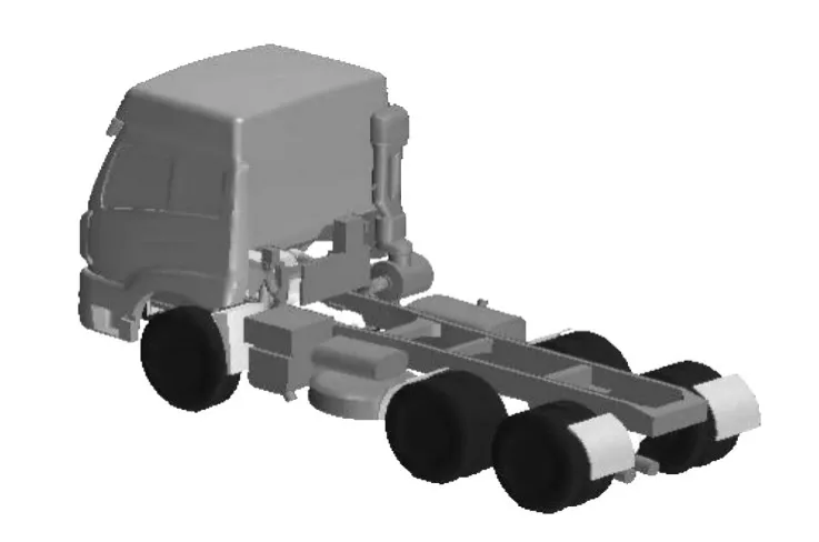
Figure 1.Simplified heavy-duty trucks model
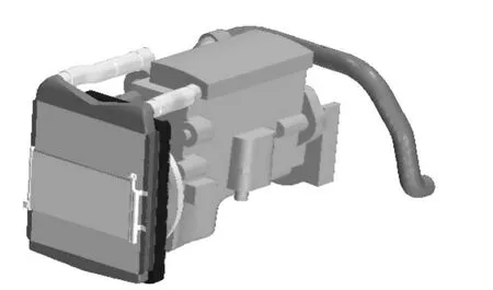
Figure 2.Engine cooling modules
The engine of the original heavy truck model is longitudinally placed.Fan is installed on the pump shaft,which drives the belt.And the belt drives the pump and the fan rotating.Figure 3 illustrates that in order to match to the water pump shaft the fan shaft has an angle with the radiator.As a result of the existence of this angle,the orthographic projection area of fan on the radiator is less than the parallel,and the position of the fan is lower than the center of the radiator,so it weakens the suction of fan for cooling air.

Figure 3.Prototype Y=0 section
Three kinds of improved cases were designed and the mathematical models were established:
1)Case 1:Install the fan to the location paralleling to the radiator and make the fan shaft perpendicular to the radiator,which is in the center of the radiator core,as shown in Figure 4.
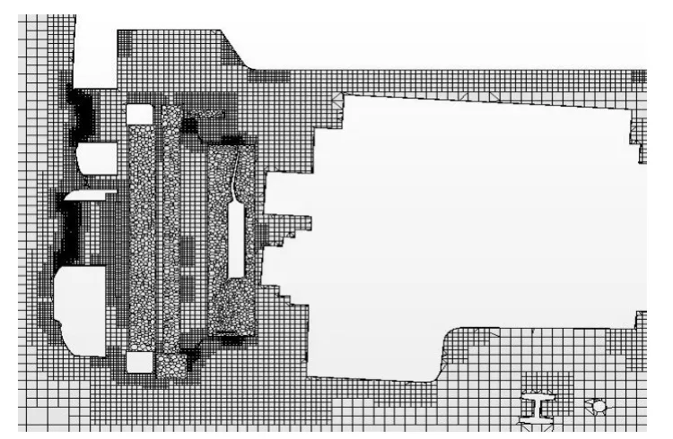
Figure 4.Case 1 Y=0 section
2)Case 2:For the layout form of cooling modules,traditional form of arrangement is intercoolerradiator-fan.The layout form of case 2 adopts intercooler-fan-radiator.So the fan is placed in the middle of the intercooler and radiator,and this reduces the air temperature which flow into the radiator and increases density and flow rate[7],as shown in Figure 5.
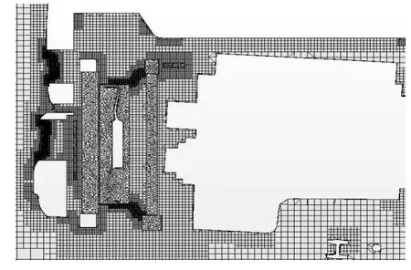
Figure 5.Case 2 Y=0 section
3)Case 3:There are three inlets in the front of the heavy truck,which are respectively the upper grille,the rubber decoration,and the lower grille.Figure 6 shows the area of the grille and the area of the radiator in the YZ plane is only a small overlapping part,so only a small part of the air overflowed from the upper grille flow into the intercooler and the radiator.Other parts outflow from cooling parts above.Due to not making full use of the cooling air,it goes against the engine cooling modules’cooling performance.Case 3 based of Case 1 is the radiator modules shift upward.In the process of upward shift,there are five small solutions to be analyzed.
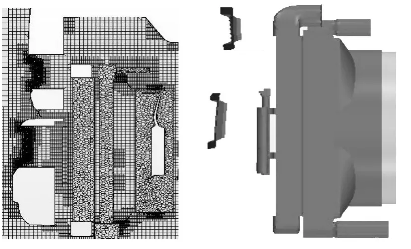
Figure 6.The front grille of the truck and cooling modules’relative locations
By measured,there are 200 mm space cooling modules can be moved along the Z axis.There are 40 mm,80 mm and 120 mm,160 mm and 200 mm,as shown in Figure 7(a)~(e).
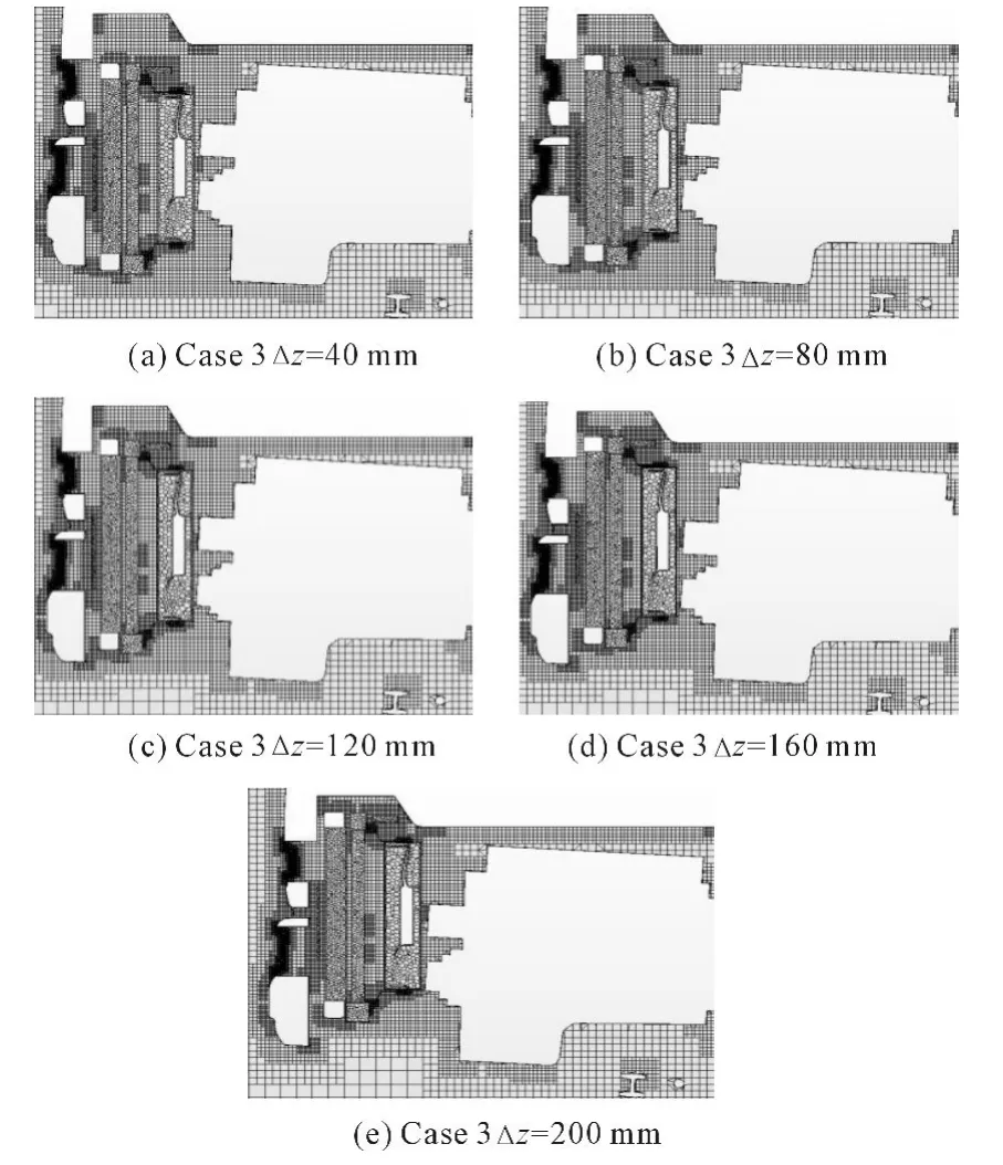
Figure 7.Case 3 Y=0 section
2.2.Grid generation
The three-dimensional model of the truck is imported to the pre-process CFD software Hyper-mesh for topology,repairing surface and meshing surface grids.Different parts use different sizes.Grids in certain regions where the details are required should be dense and divided into triangular surface mesh[8].
When generating volume mesh,first we should establish a computational domain to simulate numerical wind tunnel tests.The distance from the front boundary of the computational domain to the front of the truck is twice as long as the truck’s length.The distance from the rear boundary of computational domain to the rear of the truck is five times as long as the truck’s length.The width of computational domain is 7 times as long as the truck’s width.The height of computational domain is 4 times as long as the truck’s height.So this computational domain can insure that the flow of near the engine compartment can’t be affected,as shown in Figure 8.
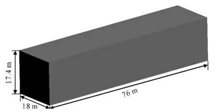
Figure 8.Computational domain size
After building the computational domain and dividing the surface mesh,we should divide the volume mesh with STAR-CCM+.The main area is divided as the trimmer grid.The condenser,intercooler,radiator core and fan zoning is divided as the polyhedral mesh.For the space around the body,the part of the front grille,the space around the engine compartment cooling system and the space between grounds,we should refine the volume mesh to well capture the flow conditions of the position we concerned.Because of the presence of the wall surface boundary layer around the automobile generating a large flow velocity gradient,the outer surface of the truck and the inner surface of the engine compartment are extruded with the boundary layer along surface normal when we divide the volume mesh.The grid number of vehicle computational domain is about 11 846 000.Figure 9 is volume mesh on Y=0 coordinate crosssection.Other cases use the same meshing schemes.
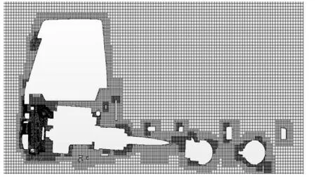
Figure 9.Heavy-duty trucks Y=0 section volume mesh
2.3.Choosing numerical methods
The air flow in the automobile engine compartment is determined by the flow of airflow field around the truck,so the simulation calculation process is coupling with the automotive external flow field and the automotive internal flow field.Automotive external flow field and internal flow field of engine compartment are separated.Simulation condition is that the engine is at the maximum torque point when vehicle speed is 30 km/h,much lower than 100 m/s,so this low speed flow is belong to the incompressible flow.We select a three-dimensional,unsteady,incompressible and viscous flow model[9].The control equation is Reynolds Averaged Navier-Stokes equations(RANS).The turbulence model is Realizable model.There are many curved walls in engine compartments,so Realizable k-e model has a good effect for simulating the boundary layer flow,the separated flow and the vortex flow[10].
2.4.Boundary conditions
The simulation process in the article is coupling with the automotive external flow field and the automotive internal flow field.Boundary conditions can be classified as the external boundary conditions and the internal boundary conditions.The external boundary conditions include inlet boundary conditions,outlet boundary conditions and wall boundary conditions of computational domain[11].Internal boundary conditions include engine compartment cooling systems and engines.The condenser,the intercooler and the radiator of cooling systems are porous media model to simulate,the fan use MRF methods to simulate,the wall of engine is setting to the corresponding thermal boundary[12].In order to simulate working conditions of heavy-duty trucks climbing at the maximum torque point under the highest summer temperature,fan speed is 1 400 r/min,the ambient temperature is 40℃,and the flow rate of the radiator circulating water is 22 m3/h.The inlet boundary condition is velocity inlet,the vehicle speed is 30 km/h,and the temperature is the highest possible temperature in summer 40℃.The outlet boundary condition is pressure outlet,and the pressure is the standard atmospheric pressure,the relative pressure is 0 Pa.The condenser,the intercooler and the radiator are the porous boundaries[13].There are heating parts of the engine compartments engine block,cylinder head,exhaust,turbo,etc.Thermal boundaries need to be according to the true situations to set.In star-ccm+ ,the condenser,the intercooler and the radiator are heat sources.
3.Results analysis and discussion
Figure 10(a)and(b)respectively show a velocity vector and a velocity scalar contour of the internal flow field of the prototype heavy-duty truck engine compartment at Y=0.Figure 11(a)and(b)respectively show a velocity vector and velocity scalar contour of the internal flow field of the prototype heavy-duty truck engine compartment at Y=0 when Case 1 change the location of the cooling fan.It can be seen that how the Case 1 impact on the velocity field of the entire engine compartment.
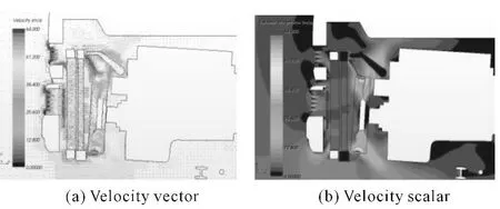
Figure 10.Prototype Y=0 section

Figure 11.Case 1 Y=0 section
Contrasting with the velocity vector and velocity scalar contour of prototype heavy-duty trucks and Case 1,the flow velocity around the intercooler and the radiator in engine compartment of Case 1 is higher than the flow velocity of prototype heavy-duty trucks’.Low velocity Vortex regions in the cab’s floor of the prototype become small,and the wind speed becomes faster in these regions.The engine compartment cooling air flow speed becomes larger so that the engine compartment cooling air flow rate increases,helping take away more heat and improving the heavy-duty truck engine compartment thermal environment.
As shown in the Table 1,we see flow-rate flowing through the condenser,the intercooler,the radiator and the fan.
Table 1 shows that the cooling flow-rate flowing through the condenser,the intercooler,the radiator and the fan of Case 1 which improved the installation location of fan has increased,and the flow-rate flowing through the fan increases more,Δq=0.292 9 kg/s.So it proves that the layout scheme for cooling modules of Case 1 can improve the thermal environment of the engine compartment,especially the flowrate increasing in the radiator has improved the thermal performance of the engine cooling system.
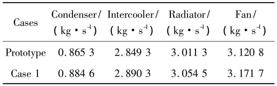
Table 1.Air flow-rate of cooling modules
We can obtain the coolant temperature of the radiator inlet pipe and the radiator outlet pipe in Case 1,as shown in Table 2.
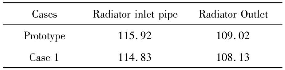
Table 2.The cooling fluid temperature of the radiator inlet and outlet pipe
Comprehensively analyzing the flow results of radiator modules and the coolant temperature of inlet and outlet of radiator,we can see that compared with the prototype,cooling performance of the Case 1 radiator has improved,but the radiator pipe water temperature is still higher than the maximum allowable temperature of the coolant with 100℃.
Figure 12(a)and(b),respectively,are temperature contours of the prototype engine compartment and Case1’s at Y=0.
Figure 12(a)shows that the prototype temperature at the top of the radiator is lower than Case 1’s due to reflow,but is still higher in other regions.The air temperature at the top of engine cylinder head is still relatively high,compared with the prototype.Due to the position change of the fan,the air flowrate flowing through the cooling module increases.The range of the high-temperature gas zone has been reduced.Through changing the location of the fan,high temperature gas reflow phenomenon has decreased.This can prevent the cooling air being secondary heated.This will help improve the effectiveness of the radiator.Compared with the prototype,the temperature of the engine compartment has decreased,but still failed to meet the cooling needs of the engine cooling modules,so we need further discussions.
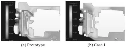
Figure 12.Y=0 section temperature contour
Figure 13(a),(b),Figure 14(a),(b)and Figure 15(a),(b),respectively,show the velocity scalar and the temperature contour of the prototype,Case 1 and Case 2.Case 2 is based on Case 1 but the fan will be placed in the middle of the intercooler and the radiator.Comparing Figure 14 with Figure 15,the flow rate becomes faster at the condenser and the center position of intercooler because of the fan being put into the middle of the intercooler and the radiator and the pumping action of the fan.However,the flow rate of the air flowing through the radiator is much lower than that in Case 1.The airflow flowing through the radiator of Case 1 is divided into two parts,one is heated in the intercooler after the outflow,the other part does not flow through the intercooler.However,the flow passing through the radiator almost comes from the intercooler and is heated,reducing the flow-rate in the radiator,so the cooling performance of the radiator is deteriorated.Comparing temperature contour of Case 1 and Case 2,the temperature in the radiator and the engine of Case 2 is higher than that in Case1.The engine compartment cooling modules thermal performance of Case 2 has not improved,compared with Case 1.Comparing velocity scalar and temperature contour of Case 2 and Prototype’s,we can see that the flow rate of Case 2 above the radiator modules and in the zones between the top and bottom of the cab is smaller than the prototype’s,but the temperature at fan,radiator and engine is higher than the prototype’s.
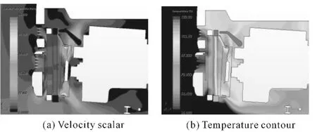
Figure 13.Prototype Y=0 section
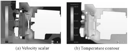
Figure 14.Case 1 Y=0 section
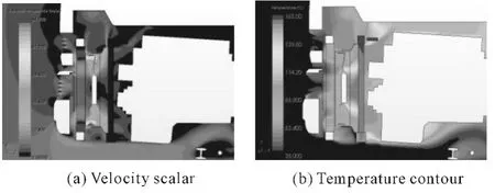
Figure 15.Case 2 Y=0 section
Table 3 shows the results of the flow-rate of the cooling modules in prototype,Case 1 and Case 2.
Table 3 shows that the flow-rate of Case 2 in the condenser is greater,compared with Case 1 and prototype.The flow-rate of the intercooler,the radiator and the fan must be less than that of the prototype and Case 1.Flow-rate test results match with the analysis of the velocity scalar and temperature contour of cooling modules.
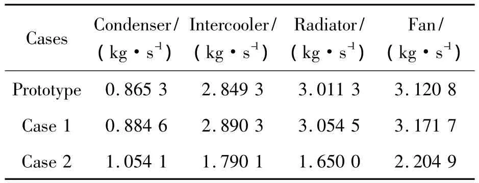
Table 3.Air flow-rate of cooling modules
By simulating Case 3 which contains five small solutions,velocity vector and velocity scalar at Y=0 cross-sectional were obtained,as shown in Figures16(a),(b)~ 20(a),(b).The flow rate passing through intercooler core in model in whichΔz=40 mm has increased compared with Case 1.Meanwhile the air at the bottom of front of heavy-duty trucks flows into intercooler,and the low-speed reflow regions above the radiator disappear.But near the front wall of heavy trucks above intercooler appears a lowspeed area,and air velocity beneath the engine increases.
Compared with Case 1,the flow-rate from engine compartment of model in whichΔz=80 mm into the intercooler increased,and the flow rate above the cooling modules accelerates.But the flow-rate from the bottom into intercooler decreases.Due to translation of the fan,the flow rate above the engine accelerates.Compared with the Case 1,the most significant changes of model in whichΔz=120 mm is that the air hardly flows from front floor of engine compartment into the intercooler.A small part of flowrate from the up-grid into the engine compartment impinges on the rack in the intercooler,and the flow rate becomes small and the air can be separated.The air of the model in whichΔz=160 mm from the upgrid into the engine compartment is no longer hampered by the shelf and is more smooth through the intercooler to a radiator.The overlapping areas of the areas projected the up-grille;and the intermediate rubber trim and lower grid on the YZ Plane and the areas projected radiator on the YZ Plane are much more than the three small solutions’ above.As shown in velocity scalar,the intercooler and the radiator air flow rate is slightly higher than the three small solutions’above in the whole.
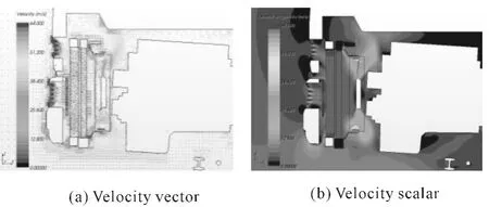
Figure 16.Case 3 Δz=40 mm
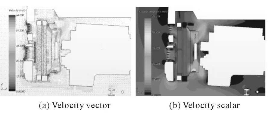
Figure 17.Case 3 Δz=80 mm
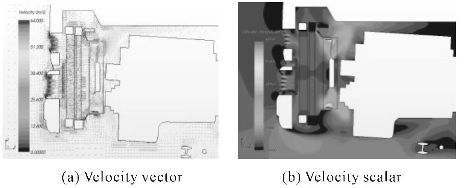
Figure 18.Case 3 Δz=120 mm
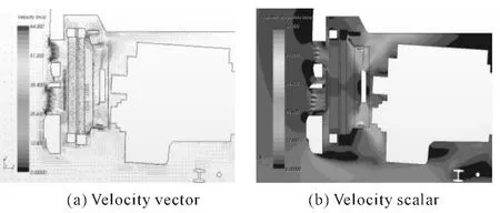
Figure 19.Case 3 Δz=160 mm
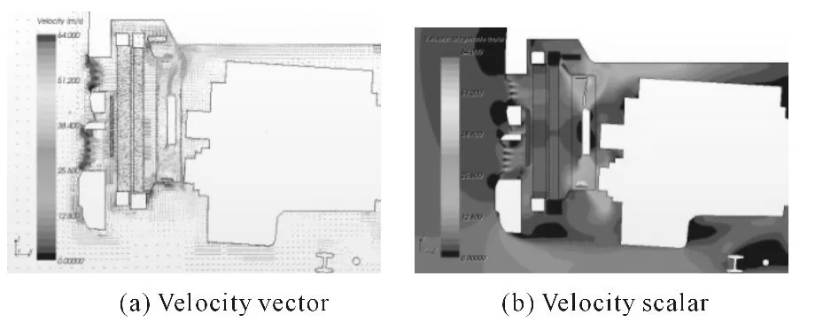
Figure 20.Case3 Δz=200 mm
In Table 4 given there are the results of the flow of the monitored cooling modules in prototype,Case 1 and Case 3 with five small solutions.This study focuses an attention on the flow of radiator.In the model in whichΔz=40 mm,there is still air flowing into the radiator below the front and this increases the flow passing through the radiator due to the flow from the up-grille into the radiator increasing and the radiator moving along Z-axis by 40 mm.The flow from the bottom into intercooler decreases in the model Δz=80 mm.Although the flow from up-grille into the radiator increases,the mass of cooling gas passing through the radiator in the modelΔz=80 mm is smaller than it in the modelΔz=40 mm.The flow from front floor of engine compartment into the intercooler is few in the modelΔz=120 mm and the flow is the least comparing with other four solutions.Although the air from front floor of engine compartment no longer passes by the radiator in the modelΔz=160 mm.The air from the up-grille into the radiator has increased and the flow reaches a maximum value in the modelΔz=200 mm.So the cooling performance of the radiator is the best.
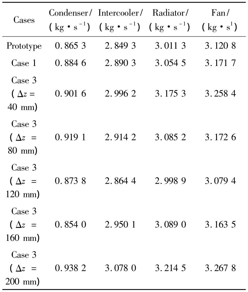
Table 4.The flow-rate of cooling modules
By simulation results,the temperature of the radiator outlet pipe is107.32 ℃ in Case 3(Δz=200 mm)where the flow-rate of the radiator is the highest but is still higher than the maximum allowable temperature of the coolant with 100℃.It proves that when the fan speed is fixed at 1400rpm,changing the layout of the cooling modules to improve the thermal performance of the engine compartment can’t reach the cooling requirements at the harshest conditions of the heavy-duty truck engine compartment thermal environment.Changing the layout of the cooling modules to improve the thermal performance of the engine compartment is limited.To make the temperature of the radiator outlet pipe less than the maximum allowable temperature,the cooling fan speed needs to be increased to meet the requirements.So this research simply selects a few points of the fan speed to try to increase the fan speed of the optimal solution to improve the thermal environment of the engine compartment.By the numerical simulation,we get that when the fan speed is 1.22 times higher than the original model,the temperature of the radiator outlet pipe is 79.00 ℃.Within the normal temperature range,the cooling needs of the engine compartment can be met.
4.Conclusion
For the cooling arrangement of the heavy-duty truck prototype engine compartment,three improve-ment programs were proposed using the same grid scheme and boundary conditions.The results of each case were analyzed and compared.The effect of the fifth solution in the Case 3 is the best.It can effectively optimize the flow structure of the engine compartment and improve the cooling performance of the radiator.The temperature of the radiator outlet pipe reduces from the 109.02 ℃ of the original model to 107.32℃.The effect of only changing the layout of the cooling modules to improve the thermal performance of the engine compartment is limited.Although changing the layout of the cooling modules can’t meet the needs of the thermal performance of the engine compartment,changing the layout of the cooling modules and then increasing the fan speed can minimize the energy consumption and improve the economical efficiency of the heavy-duty trucks.
[1] Dumas L.CFD-based Optimization for Automotive Aerodynamics[M].Berlin:Springer,2008:191-215.
[2] YU Zhi-sheng.Automotive theories(The third edition)[M].Beijing:Mechanical Industry Press,2000:10-11.
[3] FU Li-min.Automotive aerodynamics[M].Beijing:Mechanical Industry Press,2006.
[4] Fortunate F,Damiano F,Di Matteo L L,et al.Underhood Cooling Simulation for Development of New Vehicles[C]//SAE Paper,2005-01-2046.
[5] WANG Fu-jun.Computational fluid dynamics analysis-CFDSoftware Principles and Applications[M].Beijing:Tsinghua University Press,2004.
[6] LIU Chuan-chao.The flow calculation and cooling of the truck outflow and engine compartment[D].Xi’an:Northwestern Polytechnical University,2005.
[7] Zhigang Yang,Bozeman J,Fred Z,et al.CFRM Concept for Vehicle Thermal System[C]//SAE Paper,2002-01-1207.
[8] WANG Sheng-xi.Analyze two-dimensional unstructured grid generation method and its application[J].Computer engineering and application,2010.
[9] FU Li-min,WU Yun-zhu,HE Bao-qin.Simulation Research on Automotive Aerodynamic Characteristics during the Overtaking Process[J].Chinese Journal of Mechanical Engineering,2000.
[10]FU De-xun.Computational Fluid Dynamics[M].Beijing:Higher Education Press,2002.
[11] LIU Xi-xia,The heat transfer numerical simulation research for Main battle tank engine compartment[D].Beijing:Armored Force Engineering Institute,2004.
[12] HE Wei,MA Jing.The comparison for multiple reference frame method and the sliding mesh method in numerical simulation of the auto front intake[J].Computer aided engineering,2007,16(3):96-100.
[13] Francois N.Using CFD for heat exchanger development and thermal management,Valeo Engine Cooling[C]//European Automotive CFDConference EACC,Frankfurt,Germany,June 29-302005.
猜你喜欢
Chinese Physics B(2022年8期)2022-08-31
水上消防(2022年2期)2022-07-22
Chinese Physics B(2022年3期)2022-03-12
吉林大学学报(理学版)(2021年5期)2021-09-22
水上消防(2021年3期)2021-08-21
吉林大学学报(理学版)(2021年2期)2021-03-25
水上消防(2020年5期)2020-12-14
吉林大学学报(理学版)(2020年6期)2020-11-26
生物骨科材料与临床研究(2020年4期)2020-08-31
船舶标准化工程师(2015年5期)2015-12-03
