
Synthetical optimization of the structure dimension for the thermoacoustic regenerator
2022-03-12 07:44HuifangKang康慧芳LingxiaoZhang张凌霄JunShen沈俊XiachenDing丁夏琛ZhenxingLi李振兴andJunLiu刘俊
Chinese Physics B 2022年3期
Huifang Kang(康慧芳) Lingxiao Zhang(张凌霄) Jun Shen(沈俊)Xiachen Ding(丁夏琛) Zhenxing Li(李振兴) and Jun Liu(刘俊)
1Beijing Institute of Technology,Beijing 100124,China
2Technical Institute of Physics and Chemistry,Chinese Academy of Sciences,Beijing 100190,China
Keywords: thermoacoustic,regenerator,hydraulic radius,regenerator length
1. Introduction
Due to thermoacoustic effects, the thermoacoustic engine(TAE)can convert the heat to the acoustic wave,and the thermoacoustic cooler(TAC)can also pump heat through the acoustic wave. The regenerator for thermoacoustic conversions is the core of the thermoacoustic devices. In the TAE,acoustic waves are triggered when a steep temperature gradient is established along the regenerator. Acoustic waves cause gas parcels in the regenerator to go through a thermodynamic cycle consisting of compression,heating,expansion and cooling processes. As a result, the conversion process from heat to acoustic energy does not have any moving parts.[1]In the TAC,when the acoustic wave passes through the regenerator,a temperature gradient along the regenerator with a certain coefficient of performance(COP)is established. Gas parcels affected by acoustic waves in the regenerator undergo the thermodynamic cycle consisting of compression, cooling, expansion and heating processes. Thus, moving parts are not required in the heat pumping process,[2]as well.
In 1962,Carter[3]enhanced the thermoacoustic effects by inserting a regenerator into the Sondhauss tube[4]and stimulated the investigation of the thermoacoustic regenerator function. In 1979, Ceperley[5]firstly described the thermoacoustic regenerator as an energy conversion apparatus, and experimentally testified the thermoacoustic conversion function.Fundamentals of physical principles underlying the regenerator were investigated and analyzed in previous papers,[6,7]while the regenerator’s parameters were optimized by several researchers.[7-12]
Swift[7]studied the hydraulic radiusrhin the thermoacoustic system and obtained the empirical values:rh/δk~1 for standing wave engine andrh/δk ≪1 for traveling wave engine,whereδkis the thermal penetration depth. Tijani[8]studied a standing wave thermoacoustic cooler and put forward thatrh=1.25δkwas optimal for the cooling power,rh=2.0δkled to the lowest temperature,and the highest efficiency could be reached whenrh=1.5δk. Yu[9]found that a measured optimal value wasrh≈(0.3~0.2)δvfor the excitation of the system with the viscous penetration depthδvin a traveling wave thermoacoustic engine. Raspet[10]presented the correlation of the coefficient of performance of the thermoacoustic cooler with the standing wave ratio and optimized the regenerator structure by adjusting the standing wave ratio. Tijani[11]experimentally investigated the effect of Prandtl number on the performance of a thermoacoustic refrigerator using gas mixtures. Kazuto[12]considered correlations of the local Nusselt number distribution and analyzed heat transfer characteristics of the oscillatory flow in the engine core via numerical simulations.
However, those publications[7-12]were unilateral to understand the optimal condition for the thermoacoustic conversion. Most of those regenerator optimizations[7-12]analyzed parameters of the working field,working gas and the hydraulic radius,whereas the quantitative investigation of important parameters,for example,the length of the regenerator,on the behavior of thermoacoustic devices was still lacking. In the previous design,[13-25]the selection of the regenerator length was dependent on the experience, which caused the design with some blindness and results without prescient considerations,as well as the limited performance rather than the optimal.
Thus,this paper presents a normalized parameter,the regenerator operation factor,based on the linear thermoacoustic theory for the small-amplitude condition without the nonlinear linearity involved. The influence of frequency on efficiency can be controlled and offset manually,while the thermoacoustic devices with various frequencies can perform the same efficiency. This is of significance to guide the miniaturization design of the thermoacoustic device. Moreover, by extracting and analyzing the regenerator operation factor in the basic thermoacoustic formulas,the parameters relative to the regenerator length are obtained and can be used to optimize the regenerator length. Finally, this paper synthetically optimizes the structure dimension of the thermoacoustic regenerator by combining the regenerator operation factor,relative hydraulic radius and acoustic field parameter.
2. Thermoacoustic formula extracting
2.1. Heat flow
In the thermoacoustic regenerator model, ordinary thermal conduction in direction is neglectable. The time-averaged heat flow generated across regenerator due to the hydrodynamics transport is[26,27]


where Im[ ] indicates the image part,U1is the volume flow rate,fvandfkare the spatially averaged Rott’s functions,which also depend on the specific channel geometry under consideration.
Expressions offvandfkare known for most geometries[26]and the solutions for most of these geometries are actually very similar. Therefore,this paper only takes the parallel plate-type regenerator as a case,and other types of regenerators can be analyzed in the similar way. They=0 is defined at the centerline of the spacing between two adjacent parallel plates

Theψis the regenerator operation factor, which is derived from the basic thermoacoustic formulas and reflects the human-operable factor in the regenerator, including not only the structure dimension (e.g.,lN), but also the operation parameter(e.g.,Th). By extracting and analyzing the regenerator operation factor in the basic thermoacoustic formulas,the parameters relative to the regenerator length are obtained,andψis defined as

wherelNis the normalized length of the regenerator and is defined aslN=lreg/λ,the ratio of the length of the regeneratorlregto the wavelengthλ,This the temperature of the hot end,andTcis the temperature of the cool end.
2.2. Acoustic power
The average acoustic power d ˙E2produced in a length dxof the regenerator is expressed as[27]

The first two terms in Eq. (12) are always negative because they have no concern with the temperature gradient alongxand describe the consumption of the acoustic power.The first term describes the viscous dissipation of the acoustic wave. It is proportional to|u1|2and independent of thermal conductivity. The second term describes the thermalrelaxation dissipation and is proportional to|p1|2and independent of viscosity. The third term is called the source term as it describes not only the production but also the consumption of acoustic power. Only if dTm/dx/=0 will the last term exist. As shown in Eq. (12), there are two means to produce more acoustic power:one is to reduce the viscous and thermalrelaxation dissipation,while the other is to increase the newly produced acoustic power.
For simple analysis,the average acoustic power gain can be written as

2.3. Second law efficiency of the TAE
The first law efficiencyη1divided by the Carnot efficiencyηcequals the second law efficiencyη2,that is,

According to Eqs.(9),(13)and(14),it can be yielded

2.4. Second law coefficient-of-performance of the TAC
The first law coefficient of performance COP1divided by the Carnot coefficient of performance COPcequals the second law coefficient of performance COP2,that is,

As shown in Eqs. (7), (8), (15), and (17), the thermoacoustic conversion efficiency is determined by six parameters:the working gas parametersγandσ,the structural parametersζandψ,and the acoustic field parameters|ZN|andφZ.
Due to extracting the factor ofψandζ, the frequency does not exist in the efficiency formula. The effect of the frequency on the efficiency can be transformed into the effect of the normalized length of the regenerator on the efficiency. It can be controlled and offset manually,which means that thermoacoustic devices with different frequencies can perform the same efficiency by adjusting the radius dimensions in proportion to the axis dimension to keepζandψconstant. This is significant to guide the miniaturization design of the thermoacoustic device.
For example,there is a high-efficiency thermoacoustic device with the length ofl1, the frequency off1and the hydraulic radius ofr1h. For designing a miniature thermoacoustic device with the same efficiency,ζandψshould be kept constant in the structure designing. Consequently, according to the definitions ofζandψ,r2h,l1andf2can be gotten as follows:

3. Results and discussion
Under the condition of helium as the working gas and|ZN|=10,the second law efficiency of the engineη2and the second law coefficient of performance of cooler COP2are calculated within certain ranges of operation factor of regeneratorψ,relative hydraulic radiusζand leading phaseφZ.
3.1. Regenerator of TAE
In this section, the regenerator of the thermoacoustic prime mover is discussed. The case of d ˙E2/dx >0 is of significance, and elsewhere, the case of d ˙E2/dx ≤0 is neglected and assumed to be zero in the figures. According to Ref. [28], this section just discusses the acoustic field with-90° <φZ <0 in which region the TAE can gain a higher acoustic power and better efficiency.
Figure 1 showsη2as a function ofζandψwith differentφZ. Furthermore,the maximumη2,the optimalζand the optimalψwith differentφZare summarized in Figs.2 and 3. It can be found that the maximumη2=0.786 operation occurs whenζ=0.15,ψ=42.1 andφZ=-9°.

Fig.1. The effect of ζ,ψ and different φZ on η2: (a)φZ =0°,(b)φZ =-30°,(c)φZ =-60°,(d)φZ =-90°.

Fig.2. The maximum η2 with different φZ.
As shown in Fig.2, the maximumη2does not appear atφZ=0°, but atφZ=-9°. When gas works at the leading phaseφZ=0°, the regenerator achieves the reversible thermoacoustic conversion in theory. The reversible thermoacoustic conversion can be realized by the reversible thermal contact which requires an infinitesimal hydraulic radius of the regenerator. However, this will lead to infinite viscous dissipation which will weaken the thermoacoustic gain and efficiency. So the finite hydraulic radius is adopted in the real traveling wave device,which makes the oscillating temperature of gas parcels lag the oscillating displacement.It indicates that the phase difference between the oscillating temperature and the oscillating pressure deviates from 90°because of the thermo-relaxation.Under such condition, for improving the thermoacoustic efficiency and gain,φZ=-9°/=0°is of significance to match the phase deviation resulted by the thermo-relaxation.
As shown in Fig.3,asφZincreases from-90°to 0°,the optimalψincreases, and thus the optimal length of regenerator decreases because oflN∝1/ψas shown in Eq. (11). It indicates that the optimal regenerator length of the standing wave engine is longer than that of the traveling wave engine.This property can explain the different lengths of the regenerators in the cascade TAE designed by Swift.[13]In 2003,Swift designed a cascade thermoacoustic engine consisting of three stages,and the lengths of the regenerator were 0.26 m,0.031 m and 0.042 m,separately.It indicates that the regenerator length of the first stage is much larger than those of the second stage and the third stage,because the first stage works in the standing wave field while the other two stages work in the traveling wave field.

Fig.3. The optimal ζ and the optimal ψ for the maximum η2 versus φZ.

Fig.4. The effect of ζ,ψ and φZ on COP2: (a)φZ =-180°,(b)φZ =-150°,(c)φZ =-120°,(d)φZ =-90°.


3.2. Regenerator of TAC
This section focuses the discussion on the regenerator of the TAC.The case of ˙Q >0 is significant,and elsewhere,the case of ˙Q ≤0 is neglected and to be assumed as zero in the figures. According to Ref.[19],this section just discusses the acoustic field with-180°<φZ <-90°in which the TAC can gain a higher cooling power and coefficient of performance.
Figure 4 shows the variation of COP2with variousζ,ψandφZ. Furthermore,the maximum COP2,the optimalζand the optimalψwith differentφZare summarized in Figs.5 and 6. It is quite obvious that the maximum COP2=0.786 operation occurs whenζ=0.17,ψ=25.9 andφZ=-169°.

Fig.5. The maximum COP2 with different φZ.
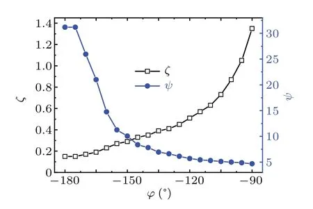
Fig.6. The optimal ζ and the optimal ψ for the maximum COP2 versus φZ.
As shown in Fig. 5, the maximum COP2does not appear atφZ=-180°,but atφZ=-169°. Similarly to the phenomenon that appears inη2optimization,the finite hydraulic radius valueζ=0.17 is accepted due to the viscous dissipation,and thenφZ=-169°/=-180°is important to match the phase deviation because of the thermo-relaxation.
As shown in Fig. 6, withφZincreasing from-180°to-90°, the optimalψdecreases, and thus the optimal length of regenerator increases because oflN∝1/ψas shown in Eq. (11). It indicates that the optimal regenerator length of the standing wave cooler is longer than that of the traveling wave cooler.
4. Conclusions
Based on the linear thermoacoustic theory,this paper extracts a normalized parameter named the regenerator operation factor, and then synthetically optimizes the dimension of the thermoacoustic regenerator by combining the regenerator operation factor, relative hydraulic radius and acoustic field parameter.
1)Due to extracting the regenerator operation factor and relative hydraulic radius, it is found that the influence of the frequency on the efficiency can be controlled and offset. Thermoacoustic devices with different frequencies can perform the same efficiency by adjusting the radius dimensions in proportion to the axis dimension. This is of significance to guide the miniaturization design of the thermoacoustic device.
2) The parameters relative to the regenerator length appear in the basal thermoacoustic formulas by extracting and analyzing the regenerator operation factor. It can help us optimize the length of the regenerator more easily,and control the temperature more effectively in the running process.
3)As the leading phase deviates from the traveling wave phase to the standing wave phase, the optimal length of the regenerator increases. It indicates that the optimal regenerator length of the standing wave device is longer than that of the traveling wave device.
4) Under the condition of helium as the working gas and|ZN| = 10, the maximum second law efficiency of engineη2=0.786 operation happens whenζ=0.15,ψ=42.1 andφZ=-9°/=0°because of the thermo-relaxation. The maximum second law coefficient of performance of cooler COP2=0.786 operation happens whenζ=0.17,ψ=25.9 andφZ=-169°because of the thermo-relaxation.
5) The finite hydraulic radius is selected because of viscous dissipation, and the optimization of the leading phase is not the traveling phase because of the thermo-relaxation.
Acknowledgement
Project supported by the National Natural Science Foundation of China(Grant No.51925605).

- Chinese Physics B的其它文章
- Measurements of the 107Ag neutron capture cross sections with pulse height weighting technique at the CSNS Back-n facility
- Measuring Loschmidt echo via Floquet engineering in superconducting circuits
- Electronic structure and spin-orbit coupling in ternary transition metal chalcogenides Cu2TlX2(X =Se,Te)
- Characterization of the N-polar GaN film grown on C-plane sapphire and misoriented C-plane sapphire substrates by MOCVD
- Review on typical applications and computational optimizations based on semiclassical methods in strong-field physics
- Quantum partial least squares regression algorithm for multiple correlation problem