
Induced current of high temperature superconducting loops by combination of exciting coil and thermal switch
2022-03-12 07:44JiaWenWang王佳雯YinShunWang王银顺HuaChai柴华LingFengZhu祝凌峰andWeiPi皮伟
Chinese Physics B 2022年3期
Jia-Wen Wang(王佳雯), Yin-Shun Wang(王银顺), Hua Chai(柴华), Ling-Feng Zhu(祝凌峰), and Wei Pi(皮伟)
State Key Laboratory of New Energy Renewable Power System,North China Electric Power University,Beijing 102206,China
Keywords: bridge,high temperature superconducting(HTS)sub-loops,induced current,thermal switch
1. Introduction
With the development of its technology and the lowering of cost,the second-generation high temperature superconducting(2G-HTS)RE-Ba-Cu-O(REBCO,RE is rare earth)tape has received wide attention in HTS magnet application.[1]Scientific research institutions have obtained some achievements through continuous exploration in electrical engineering and the superconducting magnets based on 2G HTS tapes.[2-4]The 2G HTS tape has high current carrying capacity, excellent mechanical properties and field performance in high field, it can thus produce strong magnetic fields above 25 T which the low temperature superconducting (LTS) magnets cannot achieve.[5]However, HTS magnet made of 2G HTS tapes still faces many challenges such as twisting, transposing and soldering joint without resistance. The LTS wires can operate in persistent current mode (PCM) in the application of magnets because the technique for soldering the joints without resistance in these superconductors is already well developed.[6-8]According to the standard BS EN ISO 17279-1:2018,however,soldering technique with the Joint resistance under 10-15Ω becomes bottleneck of the closed-loop operation for HTS magnets.[9]Consequently,the heat-leakage from current leads the operation cost to increase.
To realize PCM of HTS magnet, several HTS magnet models made of 2G HTS tapes have been proposed and excited by flux pump or field cooling in recent years.[10,11]There are several methods of processing HTS magnets in which closedloop forms without soldering.[12,13]Particularly,an HTS magnet model,stacked by 2G HTS tapes with two slits in the middle of tape, was proposed, and several exciting methods with PCM were preliminary confirmed.[14,15]Each loop of the magnet is independent in carrying the persistent current and any individual loop fault or critical current weak point will not affect the performance of the whole magnet. Therefore,it is significant to study the operation mechanism of magnetic flux in the loops. Note that the charging loop follows the transformer principle that the current on the loop is proportional to∂Φ/∂t,and the load loop is only related to the magnetic flux because superconductors obey the law of fluxoid conservation.[16]
This paper aims to realize the influence of magnetic flux on induced current in load loop,which is excited by flux pump consisting of exciting coil and thermal switch. The 2G HTS tape made of an HTS coated conductor is divided into three parts by two slits and stretched out to make jointless persistent current loops. An exciting coil is located in one sub-loop,and a magnetic field is generated in another sub-loop by the flux pump. The thermal switch is located on a bridge between two slits. An experimental setup is established to investigate the induced current of HTS sub-loops under triangular wave magnetization. The excitation principle is further proved by comparing the experimental results with the simulation results.The influence of magnetic flux on induced current in load loop is present and verified in experiment in 77 K. Results show that the HTS sub-loops can be excited by a coil with thermal switch, and the induced current increases with magnetic flux of exciting coil increasing, which is promising for persistent current operation mode of HTS magnets.
2. Configuration and principle of flux pump
2.1. Configuration of HTS loops
The loop was made by cutting commercial 2G tapes with a thickness of 0.0681 mm and a width of 12 mm. Figure 1(a)shows the geometrical view of the 2G HTS tape with two slits.Figure 1(b)displays the picture of the tape,which is composed of Hastelloy layer,buffer layer,REBCO film,silver layer and copper layer. Main parameters of the HTS loop are shown in Table 1.

Fig.1. Schematic diagram of 2G HTS tape with two slits(in units of mm):(a)geometrical view and(b)overview.

Table 1. Thickness of main components of 2G HTS tape.
2.2. Principle of flux pump
The HTS loop can be simplified into two superconducting closed-loops: the closed-loop of the excitation coil,called‘charging loop’, and the sub-loop formed in the large circle,named‘load loop’. The common or sharing branch part of the two sub-loops is termed the bridge. The flux pump consists of an applied excitation coil wound by copper wire and a thermal switch located in the bridge as shown in Fig.2. The excitation coil is located inside the charging loop,and the magnetic field accumulates around load loop.

Fig.2. Principle diagram of flux pump for two HTS sub-loops.
A triangular wave pulse current is generated in the excitation coil of charging loop by a power supply. The thermal switch is realized by a heating resistor on the bridge. Time sequences of both current and temperature of thermal switch are indicated in Fig.3. Their periods areτ5-τ1.

Fig.3. Time-dependent waveform of current in excitation coil and temperature in thermal switch.
Excitation steps are as follows. 1) The pulse current source in excitation coil turns on at momentτ1, the flux goes through the loops,and the bridge transfers from superconducting state into normal state gradually which is equivalent to the scenario that the thermal switch is off. 2)The bridge is heated and the resistor is persistent existence at momentτ2and extends toτ4, the thermal switch is thus off within duration ofτ2toτ4. The flux in the loop increases tillτ3. 3) The current flows in the HTS loop,in which the pulse current source reaches a maximum at momentτ3. The resistance of switch starts to decreases atτ4and is on again at momentτ5. 4)Repeat steps 1)-3),the net current increases step by step,that is,the magnetic field accumulates in the load loop.
3. Analysis of magnetic flux generated by in-
duced current of 2G HTS loop
3.1. Excitation process
When a superconducting loop is placed in a changing applied field and the current of the tape is below its critical current,it induces a compensating current inside the loop. Therefore,equation(1)is used to describe the relationship between the change of total magnetic flux inside the ring and the induced current according to Faraday’s law,[17,18]

whereφis the total flux,Ldenotes the inductance, andi(t)refers to the induced current in the loop,Vc=Ecl,Ec=1×10⁻⁴V/m is the criterion for defining critical current,n=30 is the power exponent describing theE-Jrelations,lis the length of the ring, andIcis the critical current of the loop.
Equation (1) exhibits the relationship between magnetic flux and induced current in the tape. It can be seen that the magnetic flux is related to the changing rate of the induced current,and a dissipative state emerges which is characterized by an electric field of a resistive nature. When the changing rate is very slow,the heat dissipation inside the sample holder is small. It is observed that the induction of persistent current is directly related to the emergence of a dissipative state.Therefore,the magnetic flux is dominated by the resistive behavior instead of the ramping rate of the applied field,and the temperature inside the loop remains constant.
For even higher maximum current values,magnetic field variations are significant, which reduces the critical current and increases the electric field value in phase with the current.Finally,the induced current achieves the saturated equilibrium when the resistive behavior is almost unchanged.
3.2. Simulation of magnetic flux density
The finite element method(FEM)is used to perform the three-dimensional(3D)simulation of 2G HTS loop,and magnetic field is calculated by theH-formula method with the finite element software COMSOL Multiphysics. Magnetic field intensityHis introduced into Maxwell’s equations in theHformula.[19,20]The Faraday law of electromagnetic induction and Ampere’s law are demonstrated in Eqs.(2)and(3),respectively. Substituting Ohm’s law Eq.(3)and magnetic property Eq.(4)into Eqs.(2)and(3),yields Eq.(5).

whereρis the resistivity,μ0is the vacuum permeability, andμris the relative permeability.
The solving region consists of the superconducting regions and the air region. An outer boundary surrounding the superconducting and air regions must be defined in order to determine the boundary condition. The outer boundary is far larger than the HTS loop, thus the air region radius is chosen to be 10 times the outer radius. The coordinate system is shown in Fig. 3. The loop is subjected to a background fieldf(t)along thezdirection,and the current is applied to excitation coil in thexdirection,which can be imposed on the outer boundary of the model in the forms of Eqs. (6) and (7). Thef(t)is the AC magnetic field applied to excitation coil.

whereHx,Hy, andHzare the components of magnetic field intensity in thex,y,zdirections respectively.
(2)在员工对“社会保障体系”的满意度评价中,本文依据文献,设计出如下二级评价指标:社会保障制度(U221)、社会保障的缴费结构(U222)、及员工福利保障(U223)。
The electric field characteristic of the HTS loops is expressed by theE-Jpower law

whereJc(B)is the critical current density at the magnetic flux densityB.
The critical current density is related not only to the magnitude of magnetic flux density,but also to its orientation due to its anisotropy,which can be expressed at 77 K by[21]

whereB⊥andB||are the perpendicular and parallel components of magnetic flux densityBto the HTS loops, respectively,Jc0is the engineering critical current density in the selffield,B0=20 mT is the fitted parameter,α=0.65 is a dimensionless constant,γ=5 is a dimensionless fitting parameter.
Two HTS sub-loops use a combination of triangle partitioning and sweeps for finite element meshing. The sweep is used to improve mesh generation, which is suitable for such geometric models with a high aspect ratio. Free triangles are used for meshing in the geometric surface. Figure 4 shows the meshing of HTS sub-loops.
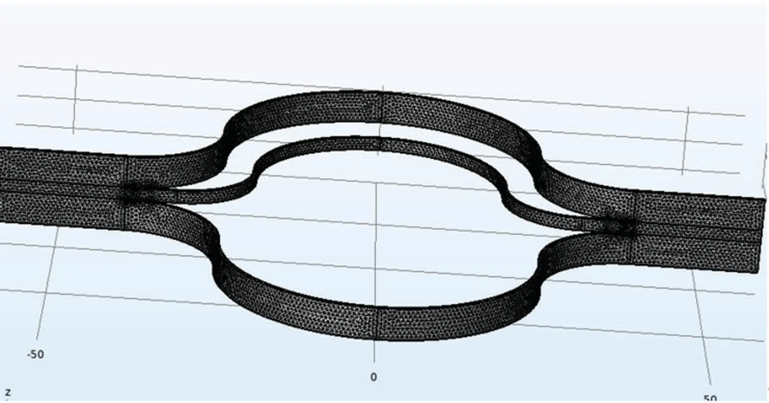
Fig.4. Meshing of HTS sub-loops using triangle division.
4. Calibration and experiments
4.1. Calibration of induced magnetic flux density and supplied current

Fig.5. Experimental arrangement for calibrating relationship between magnetic flux density and supplied current in the loop.

Fig.6. Calibrated plot of supplied current in the loop against magnetic flux density.
In order to obtain the induced current, dependence of magnetic flux density on current needs to be calibrated since magnetic flux is proportional to current. The experimental arrangement is displayed in Fig. 5, which is the same loop as that in Fig. 2. Firstly, the loop is divided into branch I and branch II, and the terminations are insulated by an insulating film such that the current is directly applied to the loop by a power supply. Then, the loop is fixed by foam, and a hall probe is placed at the same location of the loop as shown in Fig. 2, thus the linear relationship between current and magnetic flux density can be obtained according to the measured induced magnetic flux density values.
Figure 6 shows the linear relationship between supplied current in the loop and induced magnetic flux density in the loop.
4.2. Experiments of induced magnetic flux density
The experimental setup is placed in liquid nitrogen, but the equipment is under room temperature. The current source waveform of excitation coil in the flux pump adopts the triangular wave whose rising time is far longer than the transition time. The period is 30 s in the experiment. The rising time of current source is 25 s,the falling time is 5 s. After several pulse periods, the flux accumulates in the center of load loop till the HTS loop reaches saturation.

Fig.7. Equipment and experimental setup in experiment.
5. Results and discussion
According to the principle described in Section 3,the amplitude of the excitation coil is adjusted to 2 A,4 A,6 A,8 A,and 10 A,separately. Figures 8 and 9 show the measured induced current flowing in the load loop.A Hall probe is located in the load loop,which is 10 mm away from the tape as shown in Fig.2. It can be seen that the saturation induced current depends on excitation current amplitude. The larger the current amplitude,the bigger the saturation induced current is.

Fig. 8. Time-dependent induced currents in load loop with current amplitudes of 2 A and 4 A,respectively.
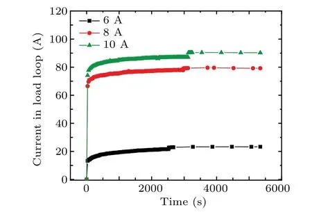
Fig. 9. Time-dependent induced currents in load loop with current amplitudes of 6 A,8 A,and 10 A,respectively.
The figures show that the induced current increases fast at first, the increasing rate slows down until saturation. The saturation-induced current is related to the current amplitude of the excitation coil. The induced current tends to be saturated at the moment 800 s,1000 s,2500 s,2800 s,and 3000 s when the current amplitude is 2 A, 4 A, 6 A, 8 A, and 10 A,respectively. This phenomenon proves that the magnetic flux of excitation coil turns larger whereas the saturation speed of induced current becomes slower. The final induced currents flowing in the ring are dominated by the resistive behavior of the rings. The maximum load currents are 1.1 A,1.8 A,20 A,78 A,and 90 A in the currents of 2 A,4 A,6 A,8 A,and 10 A respectively.
The simulation results of induced current inzcomponent in the center of load loop are compared with the experimental results, and the accuracy of simulation is verified by the experimental results in Fig. 10. The current amplitude of the excitation coil is 10 A under the control of thermal switch.

Fig.10. Comparison of measured current results with simulation results in the center of load loop.
It can be seen that the simulation results are in agreement with the experimental ones. TheH-formula method is feasible to simulate the HTS sub-loops under thermal switch excited by flux pump.
6. Conclusions
In this work,an HTS loop with two sub-loops is proposed,which is excited by a flux pump with triangular waveform current source and controlled by a thermal switch on the bridge to magnetize the loop without jointing resistance. The influence of magnetic flux on induced current in load loop is verified by numerical simulation and experiment at 77 K,which proves thatH-formula method is feasible to simulate the HTS sub-loop. The induced current produced by different magnetic fluxes in 2G HTS loop are measured at 77 K.The saturationinduced current of 2G HTS loop increases with the magnetic flux of the excitation coil increasing. The final induced currents flowing in the loop are dominated by the resistive behavior of the loops instead of the ramping rate of the applied field.
The results show that the HTS sub-loops can be excited by flux pump and the induced current increases with the augment of magnetic flux of exciting coil,which,comparing with conventional HTS magnet in PCM,is potential for HTS magnet stacked by many closed-loops operating in PCM without current leads and avoiding soldering bottleneck without resistance.
Acknowledgement
Project supported by the National Natural Science Foundation of China(Grant No.51977078).
猜你喜欢
科技资讯(2022年7期)2022-05-10
四川劳动保障(2021年9期)2022-01-18
速读·下旬(2021年11期)2021-10-12
大东方(2019年12期)2019-10-20
今日财富(2018年5期)2018-05-14
华人时刊(2018年23期)2018-03-21
科学与财富(2017年22期)2017-09-10
商情(2017年1期)2017-03-22
人间(2015年11期)2016-01-09
人间(2015年22期)2016-01-04

- Chinese Physics B的其它文章
- Measurements of the 107Ag neutron capture cross sections with pulse height weighting technique at the CSNS Back-n facility
- Measuring Loschmidt echo via Floquet engineering in superconducting circuits
- Electronic structure and spin-orbit coupling in ternary transition metal chalcogenides Cu2TlX2(X =Se,Te)
- Characterization of the N-polar GaN film grown on C-plane sapphire and misoriented C-plane sapphire substrates by MOCVD
- Review on typical applications and computational optimizations based on semiclassical methods in strong-field physics
- Quantum partial least squares regression algorithm for multiple correlation problem